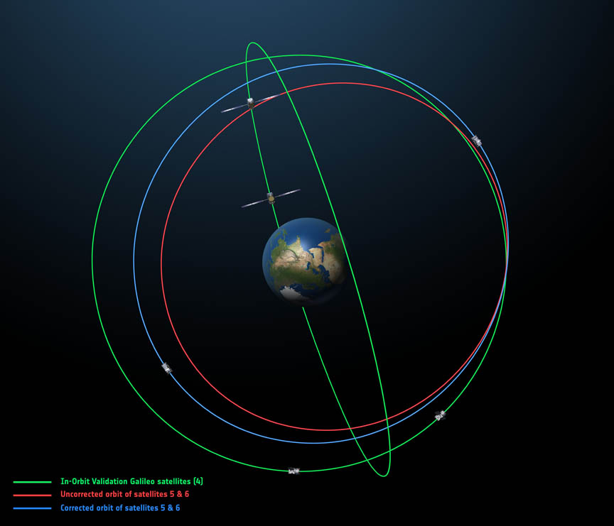
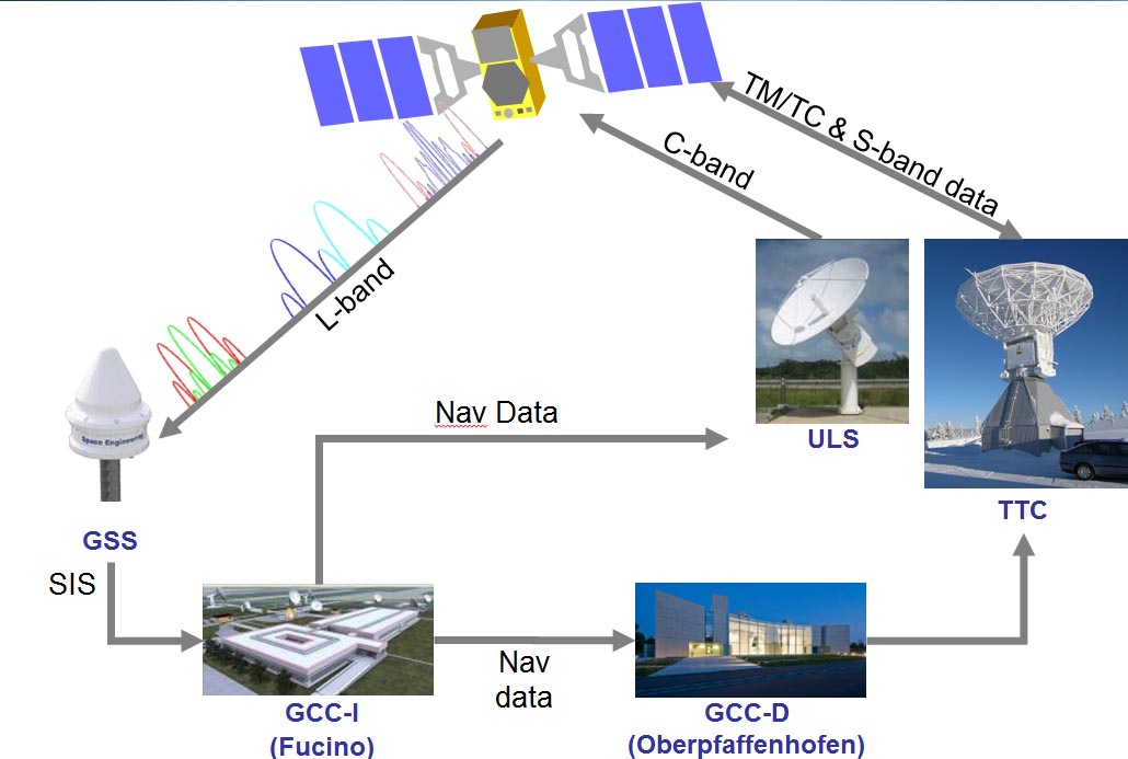
B: Applications Archives - Page 133 of 144 - Inside GNSS - Global Navigation Satellite Systems Engineering, Policy, and Design

B: Applications

March 19, 2009

Hemisphere GPS Reports Record Revenues

Steve Koles, Hemisphere GPS president & CEO

Hemisphere GPS has reported a 35 percent increase in revenues in 2008 — to a company record of US$72.7 million, versus $53.7 million the previous year. According to the company, 2008 growth was driven by strong market fundamentals in agriculture, including higher farm incomes.

Read More >

By Inside GNSS
March 16, 2009

International Conference on Precision Agriculture 2010

The tenth International Conference on Precision Agriculture will take place July 18-21 2010 at the Hyatt Regency Tech Center in Denver, Colorado USA. It is cosponsored by Colorado State University, the International Plant Nutrition Institute, and the Foundation for Agronomic Research.

Papers include those on guidance, autosteer and GPS, modeling and geo-statistics and engineering technologies and advances.

For technical questions , contact conference chair Raj Khosia at the telephone number or email below.

Read More >

By Inside GNSS
February 24, 2009

March-April 2009 Editorial Preview

To advertise, contact glen@insidegnss.com

Ad closing date: March 9

Ad materials due: March 16
Look for the March-April issue at 2009 CTIA Wireless, Las Vegas, Nevada (March 31-April 4) and the International Conference on Integrated Navigation Systems, St. Petersburg, Russia (May 25-May 27)

Read More >

By Inside GNSS
[uam_ad id="183541"]
February 22, 2009

GPS-Monitored Vehicle Fees: Change You Can’t Believe In

Transportation Secretary Ray LaHood

One change that apparently won’t happen under the Obama administration is replacing the federal gasoline tax with a GPS-monitored mileage fee.

In an interview with the Associated Press last week, U.S. Department of Transportation (DoT) Secretary Ray LaHood had suggested that his agency should look at a “vehicular miles program where people are actually clocked on the number of miles that they traveled.”

It was one of the shortest flights of a trial balloon so far this year.

Read More >

By Glen Gibbons
January 25, 2009

Trimble Rolls Out New Ag Products

EZ-Guide 500 VRA

Trimble has introduced a series of new products targeting the agriculture market where the company has been doing particularly well in recent years. These include an integrated display for manual or automated machine operation, a variable rate application (VRA) option for the company’s lightbar guidance system, and two new differential GPS receivers.

Trimble has introduced a series of new products targeting the agriculture market where the company has been doing particularly well in recent years. These include an integrated display for manual or automated machine operation, a variable rate application (VRA) option for the company’s lightbar guidance system, and two new differential GPS receivers.

The AgGPS FmX integrated display can operate as either a stand-alone manual guidance system or as part of an automated guidance, implement control or steering system. The FmX touch screen display is 12.1 inches, approximately 35 percent larger than the industry standard 10.4-inch screen, yet the display requires no more space in the cab than its predecessor, the AgGPS FieldManager, according to the company.

Read More >

By Glen Gibbons
January 16, 2009

Future Waypoints

2009
1st Quarter. Publication of 2008 Federal Radionavigation Plan (FRP).

March 24. Tentative launch date for a modernized GPS Block IIR-M satellite — IIR-20(M) —with an experimental L5 signal payload, from Cape Canaveral, Florida

Summer. Launch of IIR-21(M), last of the GPS Block IIR satellites built by Lockheed Martin Company

Summer. Publication of an initial National PNT Architecture Transition Plan

3rd Quarter. Next-Generation GPS Control Segment (OCX) Award Phase B contract

October. GPS IIIA satellite program, Key Decision Point KDP-C, Defense Space Acquisition Board (DSAB), review results of GPS III Capabilities Insertion Program and possible acceleration of capabilities for subsequent phases

Fall. Launch of first GPS Block IIF satellite

Fall. Deployment of L2C civil navigation (CNAV) message type 0 on Block IIR satellites

September 14–18. Fourth meeting of International Committee on GNSS (ICG-4) in St. Petersburg, Russia
Throughout the year: launch of three to four Compass satellites

2010

  • Critical design review (CDR) and authorization to build OCX
  • Military GPS User Equipment (MGUE) contract award: Ground-Based — GPS Receiver Application Module (GB-GRAM) [GPS Wing]
  • First Galileo In-Orbit Validation satellite launch
  • 24 GLONASS-M satellites on orbit. Launch of experimental GLONASS-K spacecraft
  • Throughout the year: launch of seven to eight more Compass satellites

2011

  • GRAM Standard Electronics Module Type E (GRAM-S/M) contract award for air and maritime platforms [GPS Wing]
  • Flight test of first CDMA signals on GLONASS; full constellation with on-orbit spares

2012

  • Civil Aviation. Design approval for GPS local area augmentation system (LAAS, known generically as ground-based augmentation system) Cat-III landing system
  • OCX Block 1 available

2013

  • L2C signal initial operational capability (IOC)
  • OCX Block 2 Available
  • Fully operational capability (FOC) Galileo constellation completed

2014

  • M-code (with flex power capability) on 24 satellites
  • Launch of first GPS IIIA satellite
  • Full-rate production, GB-GRAM

2015

  • Full-rate production, handheld MGUE and GRAM-S/M [GPS Wing]

2016

  • L2C signals transmitting all data types on 24 satellites

2017

  • Fielding of DoD modernized military GPS user equipment

2018

  • L5 signal transmitting on 24 satellites
  • WAAS approach procedures published to all instrument runways in the National Air Space

2020

  • L1C IOC

2021

  • L1C signal on 24 satellites (FOC)
By
[uam_ad id="183541"]
January 14, 2009

Autonomous Integrity

In trying to ensure integrity of GNSS navigation systems for civil aviation, various approaches have produced a range of different concepts, most of which assume the computation of a protection level. This computation is usually accomplished either autonomously (that is, entirely based on information gathered by the user receiver) or with some degree of external assistance.

In trying to ensure integrity of GNSS navigation systems for civil aviation, various approaches have produced a range of different concepts, most of which assume the computation of a protection level. This computation is usually accomplished either autonomously (that is, entirely based on information gathered by the user receiver) or with some degree of external assistance.

Such information may be provided by integrity augmentation systems (for example, space-based or ground-based augmentation systems — SBAS and GBAS). It may also be provided directly by the GNSS constellation, as it is foreseen with the future GPS III — remarkably enough, the GPS SPS Performance Standard already includes integrity performance specifications — and Galileo.

Autonomous protection-level computation techniques, however, have never been seriously considered as reliable sole means for ensuring integrity in safety-of-life (SoL) applications, not only because of the poor performances achieved, but also due to the somewhat delicate assumptions all of them rely upon. As a result, such techniques have mostly been considered as complementary to external integrity systems. One example: GPS+receiver autonomous integrity monitoring (RAIM) is not allowed as a primary navigation means for precision approach operations.

Recently, in regard of the improvements on accuracy and reliability expected from the future constellations GPS III and Galileo, new approaches have been proposed for the apportionment of integrity requirements. This is reflected, for instance, in the conclusions presented in the Phase I report of the USA GNSS Evolutionary Architecture Study (GEAS). The report suggests that the allocation of the burden for providing integrity should be balanced towards the user receiver, thus conferring user-based integrity (that is, receiver autonomous integrity) a higher responsibility.

User-based integrity is also gaining importance due to the emergence of a new field of GNSS applications, the so-called liability-critical applications (i.e., those where undetected GNSS large position errors can generate significant legal or economic negative consequences). Some leading examples of such applications are road tolling/congestion charging (both for highways and city areas), law enforcement (e.g., speed fining or surveillance of parolees) or “pay as you drive” insurance schemes.

Unlike air navigation, liability-critical applications often take place in harsh operating environments dominated by local effects such as multipath. Under such conditions these applications cannot always be monitored or aided by external (global, regional, or even local) augmentation systems.

Even in civil aviation, some landing operations could also be subject to large multipath that could put the navigation integrity at risk. For those scenarios the proposed technology would mitigate the associated risk.

One key assumption of conventional RAIM schemes is that simultaneous faulty measurements are extremely unlikely. This single-fault assumption, however, fails to hold in a typical liability-critical application scenario, where multipath is the primary source for large measurement errors and will quite frequently affect more than one measurement at a time. The single-fault assumption also fails to hold in the future air navigation scenario, where the large number of satellites made available by the joint use of several constellations (GPS/Galileo/GLONASS) will significantly increase the probability of multiple simultaneous faults.

Other assumptions common to all existing RAIM schemes include one or another statistical model of the individual measurement errors, trying in particular to bound the tails of their distributions. This sort of assumption is somewhat risky and difficult to verify, especially when the target confidence level is very high, as in the case of SoL applications such as civil aviation.

Moreover, under heavy multipath conditions most statistical assumptions of this nature just do not hold as errors caused by multipath are strongly dependent on the geometric characteristics of the local environment. (An especially acute example of this is non-line-of-sight (NLoS) multipath — that is, when a signal is tracked by GNSS equipment as it reflects from some surface despite the fact that a direct view of the satellite is occluded by some obstacle.) Hence, it is almost impossible to come up with a statistical characterization of such errors that can be used for integrity monitoring.

In this article we present a novel technique for autonomous computation of protection levels, the isotropy-based protection level concept, or IBPL for short. This technique makes no particular assumption on the statistics of individual measurement errors and provides coverage against multiple fault conditions. It takes advantage of a possible future multi-constellation scheme as its performance improves rapidly with the amount of satellites used for positioning.

Discussion in this article will show that asymptotic performance of the IBPL with respect to the number of satellites is comparable to that obtained with SBAS protection levels. This fact makes the IBPL a very promising technique, not only for liability-critical applications (the framework where it was born) but also, and very particularly, for SoL applications. We believe that IBPL fits remarkably well in the scheme proposed by the GEAS panel mentioned earlier, which recommends a shift of the integrity responsibility towards the on-board equipment.

Furthermore, as a fully autonomous method, the IBPL-based approach does not require integrity information to be transmitted on the GNSS or SBAS signal in space. This dramatically simplifies the interoperation of multiple GNSS constellations for integrity purposes, avoiding the problem of combining different integrity concepts from the various constellations or augmentation systems.

Autonomous Integrity: Two Approaches
For liability-critical applications, particularly in urban areas, local effects such as multipath — especially NLoS multipath — are by far the main source of errors and, consequently, the main threat to accuracy and integrity. In this framework, the conventional notion of faulty measurement as a large measurement error caused by a satellite malfunction is no longer useful.

. . .

IBPL: the Concept
The IBPL algorithm does not implement measurement rejection techniques but rather computes a protection level based on the all-in-view least squares solution. Of course, other IBPL solutions are possible, for instance, when different subsets of measurements are used and the one with smallest IBPL is selected. However, in its simplest form (as described in this article), this algorithm is a strict ECA concept implementation. On the other hand, this does not exclude the possibility that some refinements can be made for open-sky applications by including some kind of fault detection/exclusion mechanism.

. . .

Validating IBPL Integrity
Of course, we need to validate this new protection level concept and its underlying isotropy assumption in terms of the achieved integrity, and that must be done by experimentation with real data. We have to show that the theoretical confidence level of the isotropy-based protection level is satisfied in real life. Our discussion here cannot be considered as a full validation of the IBPL concept, but it provides significant information about the validity of the proposed algorithms.

. . .

IBPL Performance Results
From the same open-sky test run for IBPL integrity validation we derive performance figures in the form of accumulated histograms of protection level sizes.

. . .

Asymptotic Convergence of IBPL to SBAS PL
Another remarkable property of the IBPL concept is its convergence to the definition of PL currently used in SBASs (see Annex J of RTCA/DO-229D cited in the Additional Resources section at the end of this article).

. . .

About the Isotropy Assumption
Once the isotropy assumption has been accepted, the level of integrity achieved with the IBPL concept can be proven mathematically, and is therefore incontrovertible. The only controvertible point of the method is the isotropy assumption itself, or, more precisely, the extent to which this assumption represents the real world.

. . .

Conclusions
The isotropy-based protection level concept arose as the result of investigations concerning GNSS liability critical applications, in particular in urban environments. The authors found, however, that this notion also shows a great availability performance in open-sky environments and could therefore become a major breakthrough in open-sky SoL applications such as civil aviation. Isotropy-based protection levels are completely autonomous, are easily computable in real time, and rely on a single, quite verisimilar and verifiable hypothesis.

Unlike other approaches for integrity being defined as part of the GEAS initiative, the IBPL method does not require, in principle, any ground monitoring, though detection and exclusion of faulty satellites by the ground segment would help guarantee isotropy, leaving the protection level computation to the user — through the IBPL — and thus simplifying ground segment design.

IBPL’s sensitivity to the number of satellites becomes a clear advantage in open sky. With currently no more than 10 satellites in view on average (GPS only) and 20 or even more when considering either GLONASS or the future European Galileo system, this PL concept will predictably yield great performances, with smaller protection levels than those achieved nowadays by existing SBASs such as the U.S. Federal Aviation Wide Area Augmentation System or the European Geostationary Navigation Overlay Service.

For the complete story, including figures, graphs, and images, please download the PDF of the article, above.

Additional Resources
[1] Cosmen-Schortmann, J., and M. Martínez-Olagüe, M. Toledo-López, and M. Azaola-Saenz, “Integrity in Urban and Road Environments and Its Use in Liability Critical Applications,” Proceedings of the Position Location and Navigation Symposium (PLANS) 2008, Monterey, California, May 6–8, 2008
[2] GNSS Evolutionary Architecture Study, Phase I – Panel Report, February, 2008, available on-line at <http://www.faa.gov/about/office_org/headquarters_offices/ato/service_units/techops/navservices/gnss/library/documents/media/GEAS_PhaseI_report_FINAL_15Feb08.pdf>
[3] RTCA Inc., RTCA/DO-229D, “Minimum Operational Performance Standards for Global Positioning System/Wide Area Augmentation System Airborne Equipment,” 2006

By

QZSS’s Indoor Messaging System

Japan’s Indoor MEssaging System (IMES) promises to provide “seamless” indoor and outdoor positioning with no extra hardware for a GPS-enabled phone, receiver, or other portable device. But what is it?

Japan’s Indoor MEssaging System (IMES) promises to provide “seamless” indoor and outdoor positioning with no extra hardware for a GPS-enabled phone, receiver, or other portable device. But what is it?

IMES is a lesser-known part of the regional Quasi-Zenith Satellite System (QZSS) being developed by the Japan Aerospace Exploration Agency (JAXA). The QZSS program will place three satellites in high-altitude orbits transmitting ranging signals to improve navigation performance in areas of Japan that prove difficult with GPS alone. The first launch of a QZSS satellite is scheduled for 2010.

Five of six QZSS signals transmitted from these satellites will use the same signal structures, frequencies, spreading code families, and data message formats as GPS and GPS satellite-based augmentation system (SBAS) signals.

An annex to the interface specification for QZSS (IS-QZSS) sets forth the IMES signal design. (See reference in Additional Resources section at the end of this article.)

Although QZSS satellite signals will only be available in a western Pacific Ocean region centered over Japan, IMES is a separate terrestrial element based on an open specification that could be implemented anywhere.

According to the annex, the IMES signal is designed by JAXA to contribute to “the development of QZSS-ready receivers as well as satellite positioning applications by realizing the seamless positioning environment.” However, IMES signal transmitters are not part of the QZSS component; rather, the IMES specification is intended to aid third-party vendors in further development and installation of the system.

Primarily, IMES is designed to provide accurate positioning indoors where reception of GPS and other GNSS signals is blocked or unreliable. By being able to operate indoors using GPS-capable equipment (by upgrading a receiver firmware with the IMES navigation bit decoding algorithms), the system is meant to pick up where GPS fails, in a “seamless” way.

IMES is really competing with assisted-GPS or GNSS (AGPS/AGNSS), which has been used with some success — although substantial inaccuracy — for indoor positioning. In particular, its advocates advance IMES’s utility for enhanced 911 (E911) automatic location of emergency calls from mobile phone users.

At the recent International Symposium on GPS/GNSS in Tokyo, a number of technical presentations and exhibitors discussed the implementation of IMES technology by JAXA, GNSS Technologies (GNSST), and other companies. Hitachi and GNSST had receivers on their exhibit stands and graphics explaining how IMES worked.

For someone with a GPS background, these graphics were somewhat confusing. It looked as though IMES was a system of GPS retransmitters mounted to ceilings — something that wouldn’t help much at all for indoor navigation.

Further investigation, however, revealed that these transmitters, although they operate in the GPS L1 band, are in fact transmitting a completely separate signal. The IMES signal simply gives the location of the nearest transmitter, which an appropriately configured receiver can then take to be “its” position.

At this point, of course, the alarm bells go off. Transmitting in L1? To GPS users, that’s tantamount to jamming. So, is IMES the perfect answer to the “seamless” ubiquitous positioning problem – or is it a dangerous jamming threat to the integrity of GPS?

Perhaps the answer lies somewhere in between. . . . With that thought in mind, this article briefly describes the IMES program and raises several key issues about its practical use in combination with GNSSs.

The IMES Signal
In June 2008, JAXA released version 1.0 of the IS-QZSS document, which includes the IMES specification. The RF characteristics of IMES are the same as the L1 C/A code for GPS and QZSS.

Transmitted at the GPS L1 center frequency (1575.42 MHz), IMES has a bandwidth of 2.046 MHz or more including the main lobe. Like the L1 C/A code, the IMES signal is right-hand circularly polarized and BPSK-modulated with a pseudorandom noise (PRN) code.

In the current interface specification for GPS (IS-GPS-200D) the U.S. government has approved allocation of the Gold (or PRN) codes 173 to 182 for use by other GNSS applications such as IMES. The received power level at an IMES-capable receiver is specified to fall in the range between -158.5 dBW to – 94 dBW. Word structure, bit rate, and modulation are the same as L1 C/A code.

IMES Messages
IS-QZSS defines four different types of messages, as shown in Table 1 (above, right). Two messages give the location of the transmitter. Message type 0 gives the latitude (23 bits) and longitude (24 bits) in WGS-84. However, height or altitude appears as a building floor number (8 bits). Message 1 provides latitude (24 bits), longitude (25 bits), altitude (12 bits), and floor number (9 bits — with units of 0.5 floor).

Messages 3 and 4 simply send an identifier, which, according to GNSST, can then be used to address a location in a database corresponding to that ID. Messages 3 and 4 also transmit a “BD” bit, which is a border or boundary indicator, set whenever the transmitter is the one “nearest” the outdoors or a GPS-accessible area. (As yet undefined, Message type 2 is reserved for later development.)

IMES can be used by a suitably modified stand-alone GPS receiver but is primarily intended for use with a GPS-enabled mobile device. Notably, messages 3 and 4 rely on the device to be able to access a database via a network.

The Additional Resources section includes a number of articles, particularly those by D. Manandhar et alia, that describe IMES, its applications, and test results to date in greater detail.

What’s Good about IMES?
What IMES delivers that other indoor location systems does not is reliability and accuracy. When receiving an IMES signal, the receiver has a strong idea of where it is to within tens of meters. The accuracy is better than AGPS, especially in height, and receivers are not required to have high sensitivity.

The big selling point for IMES in Japan is its ability to add a lot of value to simple positioning with additional data, such as maps and route guidance. For example, locations extracted from the databases used with messages 3 and 4 can be accompanied by location-based service (LBS) information.

In fact, the location may not even be returned at all. The sorts of applications used by Hitachi and GNSST to promote or, in Australian slang, spruik IMES include indoor navigation, finding products in a store, geofencing of children, location-specific instructions in case of emergency, asset management, and so forth.

What’s Not So Good about It?
The technology is in its infancy; so, the list of problems that we will raise here looks large, but each issue needs to be dealt with if IMES is in fact going to succeed AGPS.

1. Infrastructure. For IMES to work, the transmitters need to be very densely located in all indoor spaces where location is required, at separations of 20–30 meters. This represents a massive investment in infrastructure. However, unlike AGPS, this investment does not necessarily need to be made by the telecom companies alone or even at all. Also, if the IMES infrastructure is incomplete, AGPS may still be required to fill the gaps.

2. Jamming. IMES should only affect a small area around the transmitter. However, within this area, IMES will completely jam GPS.

The QZSS specification suggests that the IMES power levels are high enough to jam GPS outdoors. A maximum transmitted signal strength of -94 dBW is about 65 dB stronger than an unobstructed GPS signal received outdoors. The receiver will generally receive the signal at a much lower level; the minimum is specified to be -158.5 dBW, but jamming is still likely to occur nearby to a transmitter. Indoors, where the direct GPS signals are strongly attenuated, the situation would be worse.

The Gold codes are designed so that a receiver should be able to detect a GPS signal that is about 21dB weaker than the strongest GPS signal. This is known as the cross-correlation margin. Advanced signal-processing techniques, such as those developed by Eamonn Glennon at the University of New South Wales, can increase this margin substantially, but even with indoor GPS, cross-correlation margins of 65 dB have not even been considered.

Other systems that have been assigned codes in the IS-GPS-200D, such as SBAS and QZSS itself, transmit at levels that do not exceed the cross-correlation margin. In practice, in Japan the levels will not be as high as those in the specification. GNSST suggest that transmitters will be limited to -100 dBW (or -70 dBm), still significantly stronger than GPS.

Initial GNSST experiments suggest that this transmitted signal strength only has a noticeable effect on a GPS receiver within one meter (with the stronger level of the specification affecting receivers out to three meters’ distance). These affected regions seem small, and independent tests should be used to confirm the GNSST results. If they are valid, IMES will only jam a relatively small area.

The system model of IMES is also not “backward compatible,” meaning that if a user has an AGPS device that has happily worked for years, once IMES is installed, that device can no longer use AGPS.

3. Seamlessness. Interestingly, in the papers presented about IMES, the word “seamless” appears prominently. The idea is that the same equipment can use GPS outdoors and IMES indoors, “seamlessly.” Some papers even claim that the seamlessness has been proven by experiment.

This isn’t quite the case, however.

Modified receivers and mobile phones have been shown to work indoors with IMES signals and outdoors with GPS, but as yet none of the published experiments appear to showing a receiver happily using IMES and transitioning without interruption to GPS outside, or vice versa. The transition from GPS to IMES should be “seamless” — that is, the receiver holds on to GPS until it is jammed or blocked indoors, by which time it has picked up IMES (as long as it is looking for it).

Going the other way is more problematic. IMES can be used until it is too weak to be received, but then the receiver should be able acquire four GPS satellites. If the equipment is being used in an environment broadcasting Messages 3 or 4, then it will have been warned by the BD bit to start looking for GPS signals. In a Message 1 or 2 environment, no such warning will have been given.

Because IMES requires the receiver to receive one IMES signal at a time, a “handover” between IMES transmitters must take place. So, while receiving from one transmitter, the receiver must be searching for others, not knowing which of the PRNs is best to search for.

The near-far phenomenon means that the current IMES transmitter will jam others until they are within the cross-correlation margin. Consequently, once a transmitter’s power has been set, maximum and minimum distances emerge for the placement of other transmitters.

These transmitters must use different PRNs or else they will spoof each other. This means that the IMES transmitters must be laid out based on a code-reuse pattern similar to the frequency-reuse patterns employed by cellular networks, with the added complication of operating in three dimensions, i.e., different floors of a building by definition have different IMES transmitters.

Returning to the question of GPS/IMES transitions, although a huge effect is not likely, this cross-acquisition between GPS and IMES will use more energy than for one system alone, if for no other reason than it increases the PRN search space by the 10 codes used for IMES.

4. “You are the ground segment.” The IMES transmitters, like GPS satellites, tell the receiver where they are. However, in the case of GPS satellites, a secure, centralized ground segment infrastructure is used to create the transmitted messages.

In the case of IMES, the lat/long/height/floor that is transmitted must come from somewhere else. Each of the locations must be surveyed in. The accuracy of this survey need not be great, because the resolution of the transmitted messages is 1–3 meters and, in any case, that position applies for regions of tens of meters.

However, the surveyed position of an IMES transmitter still needs to be accurate to, say, meters in WGS-84. Given the enormous numbers of transmitters needed for this system, a huge scope for error arises in a) the measurement of the position, b) the data entry of the position, and c) the installation of the equipment (a transmitter with a perfectly well entered position being installed in the wrong place).

5. “They are the ground segment.” Messages 3 and 4 don’t tell you your position directly. That information comes from a database. The business model put forward by GNSST suggests that the database may be owned by, “for instance, department store, underground mall and etc.”

What that means is that users may not get the position they’re looking for, just what the department store or underground mall wants them to receive. As with casinos in Las Vegas, navigating one’s way out of the shop as soon as possible may not be in the store owner’s best interest.

6. Security. Tens or hundreds of thousands of these devices are needed for IMES to operate properly. They will have to be installed in public areas such as shopping centers and railway stations, and private areas such as shops. Their installation needs to be cheap because of the sheer numbers involved.

However, if an IMES transmitter can be installed relatively simply, it is also likely to be easy to remove. A stolen transmitter, or one simply bought from the manufacturer, could cause havoc. Driving through a city with a high-powered IMES transmitter on the dashboard could cause all GPS navigators nearby to either cease working, or worse, if they are IMES-enabled, to think they were in the location of the stolen device (i.e., inside a building). It makes GPS jammers (or IMES spoofers) readily available to any small-time thief.

7. Frequency allocation and regulation. Ultimately, IMES will only ever operate in countries where the IMES signal has been sanctioned in the L1 band. This may in some cases require a change in the law before it can operate. In Australia, for instance, any transmission in the L1 band must not have an intention to jam GPS, otherwise it is considered a criminal act. IMES works by deliberately jamming GPS (or at least AGPS) in indoor environments.

Although IMES transmitters are not pseudolites, it would make sense if they were regulated in a similar way. Recently, the European Conference of Postal and Telecommunications Unions (CEPT) has taken the lead in trying to come up with a global standard for pseudolite regulation. The relevant committee is yet to report (possibly early in 2009).

Conclusion
In summary, it appears that before IMES can make significant inroads into indoor positioning, a series of hurdles must first be overcome. IMES is not a magic bullet for the current hot problem of ubiquitous or “seamless” positioning. It’s just another option to add to the list, with its own set of strengths and weaknesses.

Additional Resources
Japan Aerospace Exploration Agency, Quasi-Zenith Satellite System Navigation Service Interface Specification for QZSS (IS-QZSS) V1.0, June 17, 2008 (available on-line at <http://qzss.jaxa.jp/is-qzss/index_e.html>)

NAVSTAR Global Positioning System Interface Specification IS-GPS-200, Revision D, IRN-200D-001, Navstar GPS Space Segment/Navigation User Interfaces, GPS Wing, Space and Missile Systems Center, Los Angeles AFB, California, USA, March 7, 2006

Glennon, E., and R. Bryant, A. Dempster, and P. Mumford, “Post Correlation CWI and Cross Correlation Mitigation Using Delayed PIC,” Proceedings of ION GNSS 2007, Fort Worth, Texas, US, September 26-28, 2007

Manandhar, D., and K. Okano, M. Ishii, M. Asako, H. Torimoto, S. Kogure, and H. Maeda, “Signal Definition of QZSS IMES and Its Analysis,” Proceedings of ION GNSS 2008, Savannah, Georgia, USA, September 16–19, 2008

Manandhar, D., and K. Okano, M. Ishii, M. Asako, H. Torimoto, S. Kogure, and H. Maeda, “Development of Ultimate Seamless Positioning System for Global Cellular Phone Platform Based on QZSS IMES,” Proceedings of ION GNSS 2008, Savannah, Georgia, USA, September 16–19, 2008

Manandhar, D., and S/ Kawaguchi, M. Uchida, M. Ishii, and H. Torimoto, “IMES for Mobile Users: Social Implementation and Experiments based on Existing Cellular Phones for Seamless Positioning”, Proceedings of International Symposium on GPS/GNSS, Tokyo, November 11–14, 2008

Martin, S., and H. Kuhlen, and T. Abt, “Interference and Regulatory Aspects of GNSS Pseudolites,” Journal of Global Positioning Systems, vol. 6, no. 2, pp. 98-107, 2007

By
January 13, 2009

Blaupunkt Picks IfEN Constellation Simulator for Testing Car Nav Systems

NavX-NCS

Blaupunkt GmbH, a leading automotive electronics manufacturer, has selected the NavX-NCS multiconstellation, multifrequency GNSS simulator from IfEN GmbH as the GPS reference for production testing of its car navigation systems.

The NavX-NCS RF constellation simulator supports all present and planned Galileo and GPS frequencies (E1/L1, L2C, E5AB/L5, E6) in one box, now including the composite binary offset carrier (CBOC) signal structure for the Galileo Open Service on E1.

Read More >

By Glen Gibbons

What about GPS jamming and maritime safety, and linear carrier phase combinations?

Q: What is the effect of GPS jamming on maritime safety?

A: Although GPS jamming incidents are relatively rare they can occur; and when they do, their impact can be severe.

The General Lighthouse Authorities of the United Kingdom and Ireland (GLAs) comprise the Commissioners of Irish Lights, the Commissioners of Northern Lighthouses and Trinity House, who between them provide aids to navigation (AtoNs) for the benefit of all mariners in British and Irish waters.

In order to investigate the effects of GPS jamming, whether by intentional or accidental means, the GLAs conducted a trial in 2008 on the effect of GPS denial on marine aids-to-navigation, and ship-borne and shore-based navigation and information systems.

Today’s mariners commonly use GPS enabled devices to navigate their vessels, however large, from port to port and berth to berth.  The International Maritime Organization (IMO) mandates the carriage of electronic position-fixing systems by all vessels over 300 gross tons and those carrying passengers on an international voyage in accordance with the Safety of Life at Sea (SOLAS) convention.

The GPS position is often fed into other vessel systems, for example an electronic chart display and information system (ECDIS), the vessel’s automatic identification system (AIS), or a plotter.

The use of differential GPS (DGPS) is preferred; mariners improve their positioning accuracy and ensure integrity of their GPS derived position by using the large number of DGPS radiobeacons located around the world.

Although GPS receivers for navigation are commonplace and very conspicuous on the bridge, the use of GPS is often more inconspicuous in other AtoN and positioning devices. Examples include its use for providing position input to the onboard AIS transponder, as well as the digital selective calling (DSC) system, which has the capability to include the vessel’s position as part of a distress signal.

In addition to vessel-based systems, marine aids-to-navigation use GPS. AIS timeslots may be synchronized using GPS as a source of accurate time. AIS also provides AtoN position information based on GPS input. Synchronized lights use GPS as a common timing source, and differential GPS services provide accuracy and integrity to the mariner.

Therefore, GPS denial, whether intentional from malicious jamming or unintentional due to malfunctioning equipment such as television antennas, may affect safety both on the bridge and on-shore.

(For the rest of Alan Grant and Paul Williams’ answer to this question, please download the complete article using the pdf link above.)

Q: What are linear carrier phase combinations and what are the relevant considerations?

A: Linear carrier phase combinations are formed by adding or subtracting carrier phase measurements on two or more frequencies. Such combinations are used to improve the resulting measurement in some manner relative to the original measurements.

In this context, “improvement” usually implies removing/reducing certain errors so as to facilitate the ambiguity resolution process or increase the measurement (and, therefore, position) precision. We must note, however, that improvement in both areas is not possible and thus a design trade-off is required.

In this “solution,” we will discuss how linear carrier phase combinations are formed and the key considerations associated with this process. A discussion of some of the common GPS combinations is also provided.

Topics in the full article include Linear Combinations, Integer Nature of the Ambiguities, Magnitude of Errors in Units of Cycles, Magnitude of Errors in Units of Length.

Summary and Outlook
The analysis focuses on dual-frequency combinations. However, with the modernization of GPS and the upcoming launches of Galileo and Compass, multiple frequency combinations will be possible. Despite this, the considerations discussed in this article will still hold and can be used as a stepping stone for more advanced combinations and subsequent data processing.

(For the rest of Mark Petovello’s answer to this question, please download the complete article using the pdf link above.)

By Inside GNSS

Critical Infrastructure: The United States and GPS

So, President Obama wants to spend some money on infrastructure, eh? Well, here’s an idea: send some of it GPS’s way.

Infrastructure isn’t just concrete and rebar. We can also build highways to the stars and — pardon the clichés — bridges to the future rather than bridges to nowhere.

And talk about bang for the buck. The billion dollars or so that the United States spends on GPS each year produces many tens of billions of dollars in products and services.

Of course, a big chunk of that GPS market is outside of this country. But after our recent lamentable contribution to global financial troubles, perhaps its time to remind the world about the unprecedented U.S. generosity in creating an entirely new public utility and making it available everywhere.

Not only that, but U.S. policy forced other GNSS providers to be generous, too. As the would-be Galileo public-private partnership discovered, you can’t compete with free.

Anyway, back to Obama and infrastructure.

The Global Positioning System has many unusual, novel, perhaps even unique features. But the one that relates to the current topic is that GPS is both a critical infrastructure in itself — notably its ground control and space segments and the pervasive, strategic installation of high-performance receivers  — and a contributor to other critical infrastructures, such as communications networks or transportation.

That should earn GPS double the attention, if not twice the budget.

But there’s more. GPS not only allows us to do things that we couldn’t do before; it allows us to do them more efficiently — greater productivity at less cost, whether surveying forest boundaries or guiding a thousand airplanes at once.

And though those efficiencies may reduce the job opportunities at individual enterprises, they stimulate a far greater amount of job creation overall — design and engineering, manufacturing, professional fieldwork — most of it high-skilled and higher-paying than the positions that were lost.

The United States really hasn’t had an industrial policy since just before and during World War II, when the Roosevelt administration converted much of the nation’s jobless into public employees (Works Progress Administration, Civilian Conservation Corps), its manufacturing sector into an armament assembly line, and gasoline and foodstuffs into ration coupons.

After that, we saw occasional, isolated initiatives — the interstate highway system, the lunar missions of the 1960s, SEMATECH — large-scale infrastructure and technology programs that could have served as potential components of an industrial policy, if one had existed.

GPS can help thread the new infrastructure efforts together, and expand the role that it already plays.  Many commercial GPS manufacturers are looking forward to the opportunities that building or restoring highways, bridges, and (imagine!) maybe even railroads will bring.

But the United States is still running the GPS program as though we had all the time in the world. Well, no offense to those atomic clocks on board the GPS satellites (another first of its kind), but the world is quickly catching up with us in matters of GNSS. And, if we take a close look at the world’s four GNSS program schedules, over the next few years just about every other GNSS system is going to pass GPS by in terms of signal availability, modernity, and diversity.

The United States risks seeing its GPS brand decline amid the growing choices in the GNSS marketplace.

It’s time that the GPS leadership, civil and military, revisited its prevailing philosophy and began launching for scheduled capability, rather than as needed to sustain an aging constellation.

And, while they’re at it, they should take another look at the size of the constellation. Every other GNSS system is committed to a true 30 satellite/30 slot configuration. If the advent of the biggest infrastructure investment in American history isn’t the right time to do the same with GPS, when is?

As American poet Edwin Markham asked on behalf of the man with the hoe gazing at the ground, “Give back the upward looking and the light/ Rebuild in it the music and the dream”

By

Thales Alenia Space Italia Wins Two Galileo Receiver Development Contracts

The European Space Agency (ESA) has awarded Thales Alenia Space Italia (TAS-Italia) two contracts for development of Galileo ground station receiver equipment.

One contract is for Galileo In-Orbit Validation Element (GIOVE) phase A/B ground station receivers capable of tracking the multiplex binary offset carrier (MBOC) signal that is common to both the Galileo Open Service (OS) and the new GPS L1 civil signal, which will be transmitted beginning with the GPS III generation of satellites.

Read More >

By Glen Gibbons
IGM_e-news_subscribe