Working Papers explore the technical and scientific themes that underpin GNSS programs and applications. This regular column is coordinated by Prof. Dr.-Ing. Günter Hein, head of Europe’s Galileo Operations and Evolution.
SIDEBAR: Locating a Distress Beacon Activated in Flight
Working Papers explore the technical and scientific themes that underpin GNSS programs and applications. This regular column is coordinated by Prof. Dr.-Ing. Günter Hein, head of Europe’s Galileo Operations and Evolution.
SIDEBAR: Locating a Distress Beacon Activated in Flight
For more than 30 years, since its initial deployment in 1982, the Cospas-Sarsat system has provided valuable emergency distress detection and location information to worldwide search and rescue operators and teams. As part of an international cooperation to make available a free-of-charge search and rescue (SAR) service, the system has been credited with assisting more than 37,000 people all around the world.
The system uses satellite-based payloads, hosted by low Earth orbit (LEO) constellations (LEOSAR), to detect and locate distress signals emitted by emergency beacons carried by mariners and aviators as well as by land-based users. Cospas-Sarsat has relied on its original LEO architecture since declaration of the system’s full operational capability (FOC) in 1985. It was complemented by geostationary (GEO) satellites (GEOSAR) in 1994.
Cospas-Sarsat has proven its efficiency. LEO satellites may locate beacons almost anywhere thanks to Doppler effect with a limited instantaneous coverage. The GEO satellites have a very wide field of view, which offers real-time detection but no possibility of independent location as the Doppler effect is negligible in GEOs.
To improve performance, the system is now undergoing a profound evolution called MEOSAR, which will add SAR capability to middle Earth orbit (MEO) satellites. By the end of this decade, Cospas-Sarsat will rely on a MEO/GEO space segment, replacing the LEO/GEO design, thanks to SAR payloads hosted by three GNSS constellations: GPS, Galileo, and GLONASS.
With numerous satellites, each with an Earth coverage or footprint significantly larger than the LEO satellites (about seven times larger), the MEOSAR constellations will enable an instantaneous and worldwide coverage. Distress beacons will be detected and located more quickly and accurately than today, in as little as one beacon burst, that is, about 50 seconds. The more efficient alert notices that result will directly contribute to the efficiency of rescue operations where time is critical.
In the first step of this evolution, and for obvious reasons like continuity of service, the current Cospas-Sarsat user segments will remain unchanged. The MEOSAR system will fulfill the SAR missions for more than the 1.4 million first-generation beacons already available, which were designed for the LEO constellation and therefore not optimized for the MEO case.
In the meantime, a substantial effort is being made to define a second-generation beacon compatible with MEOSAR, with updated operational and mission requirements, as well as to establish enhanced design requirements for user equipment. This creates a unique opportunity to design a signal, together with the associated ground station processing, that can fully exploit the numerous advantages of a MEO constellation. These include such factors as increased accuracy, availability, and robustness, together with simultaneous position and velocity determination, which are very useful for locating dynamic beacons onboard aircraft.
This article takes a look at the ongoing transition, and more specifically, the design activity of a spread spectrum signal for second-generation MEOSAR. Following an overview of the Cospas-Sarsat system, we will provide technical details about the new MEO segment and its location principles, based on combined time of arrival (TOA) and frequency of arrival (FOA) algorithms. We will also discuss the ongoing validation phase, referred to as Demonstration and Evaluation (D&E). Finally, as the heart of our presentation, the current status on the new design will be explored, focusing not only on the signal design and the motives behind its introduction, but also on a preliminary assessment of its performance.
The Cospas-Sarsat Program
The Cospas-Sarsat system provides accurate, timely, and reliable distress alert and location information to SAR authorities, making it a tremendous resource for protecting the lives of users. Indeed, with a 406 MHz beacon, a distress message can be sent to the appropriate authorities from anywhere on Earth 24 hours a day, 365 days a year.
These alerts are provided to SAR operations centers using the space and ground segments to detect, process, and relay transmissions of the emergency beacons carried by users. In short, Cospas-Sarsat takes over the “search” function for “search and rescue” operations.
The system consists of a space segment and a ground infrastructure that includes ground stations, mission control centers (MCCs), rescue coordination centers (RCCs), and search and rescue points of contact (SPOCs).
As illustrated in Figure 1, when an emergency beacon (1) is activated, the signal is received by a satellite (2), and in some cases, processed onboard, and then relayed to the nearest available ground station. The ground station, called a local user terminal or LUT (3), processes the signal (or the onboard processor telemetry), and calculates the position from which beacon signal originated.
This position is transmitted to a mission control center, MCC (4), where it is combined with identification data and other information about that beacon. The mission control center then transmits an alert message to the appropriate rescue coordination center, RCC (5), based on the geographic location of the beacon. If the location of the beacon is in another country’s area of responsibility, then the alert is transmitted to that country’s mission control center.
The overall rescue chain is under the responsibility of national administrations and is free of charge for the user.
Cospas-Sarsat History
Emergency locator transmitter (ELT) beacons have existed since the 1950s for military aircraft, but they only came into general use in the 1970s after the U.S. Congress mandated that most U.S. aircraft must carry a 121.5 MHz beacon. However, only overflying aircraft could detect the emergency signals from these early ELT beacons, which resulted in rather poor detection and location capabilities along with others drawbacks.
So, in 1978, the United States, Canada, and France agreed to cooperate in introducing a satellite-based component to search and rescue, hosted on low-altitude polar orbiting satellites used mostly for meteorology, in order to assure a worldwide SAR coverage. The resulting SARSAT system served to locate existing 121.5 MHz beacons as well as newly developed ones that operated on the 406 MHz frequency and provided improved performance. The three nations were quickly joined by the USSR, now the Russian Federation, which in 1979 had started development of a similar system called Cospas (Figure 2).
The first payload, COSPAS-1, was launched in June 1982 with detection and communication of the first emergency signal via the space segment the following September. The LEO constellation achieved FOC in 1985, and was augmented from 1994 by a GEO overlay.
In 2000, the United States, the European Commission (EC), and the Russian Federation began consultations with the Cospas-Sarsat organization regarding the feasibility of installing new SAR instruments on their respective GNSS satellites to incorporate a 406 MHz MEOSAR capability into the Cospas-Sarsat system. The U.S. MEOSAR system is called the SAR/GPS, the European system is called SAR/Galileo, and the Russian system is referred to as SAR/GLONASS.
The MEOSAR system for first-generation beacons is expected to be operational before the end of this decade, and the second-generation beacons could be introduced soon after (see Table 1).
Initially founded by four countries, the Cospas-Sarsat program has grown significantly, with more than 42 countries now participating: 31 countries providing ground segment facilities and 11 more as user states. About 1.4 million beacons are currently estimated to be in use worldwide, about twice the number estimated in 2007. Since September 1982, more than 37,000 people have been rescued thanks to the Cospas-Sarsat system. In 2012, 634 SAR events were generated and 2,029 people were rescued.
System Description and Operation
As outlined previously, space and ground (user) segments comprise the Cospas-Sarsat system.
User Segment. Three primary types of beacons are used to transmit the distress signals (Figure 3): ELTs used by the civil aviation community, emergency position indicating radio beacons (EPIRBs) for maritime use, and personal locator beacons (PLBs) for personal use (therefore carried by individuals). PLBs are mainly employed for land-based applications but can be used in some cases for maritime and aeronautical activities.
When activated, beacons transmit on the 406 MHz frequency, complemented by a 121.5 MHz signal, mostly for homing purposes. The 121.5MHz is used as an homing signal internationally. However, 406 MHz is used by some administrations (e.g., the United States). The beacons may be manually or automatically activated, in the latter case by hydrostatic or gravity (G)-switch systems.
Space Segment — LEO Component. The LEOSAR constellation consists of five satellites in three orbital planes. Their altitude is around 850 kilometers, with an inclination of 99 degrees from the equator. LEO-SATs complete an orbit in about 100 minutes, with each providing global coverage for 406 MHz distress signals about twice a day (twice a day at equator but every 100 minutes at the poles).
Each LEO spacecraft, usually a weather satellite, carries an onboard receiver that detects signals from activated beacons as the satellite passes overhead. These receivers may be of two types:
- The SARR instrument (Search and Rescue Repeater) transposes and repeats to the ground in real time the signal transmitted by distress beacons. The processing is then done on the ground. The on-board SARR instrument is provided by the Canadian Department of National Defense, as part of Canada’s contribution to the system.
- The SARP instrument (Search and Rescue Processor) is able to detect, demodulate and measure FOA (Frequency Of Arrival) of the received signals. All the data are stored in the internal memory until the visibility of a ground station where the data can be downloaded. The SARP is able to process three distress signals in parallel. The on-board SARP is part of the French contribution to the system, provided by the Centre National d’Etudes Spatiales (CNES), the French Space Agency. The main advantage of the SARP is that it does not require a continuous ground visibility, as it may transmit its stored data to any LUT.
Space Segment — GEO Component. The GEO component supports the Cospas-Sarsat instantaneous alert function, with a typical coverage from 70°N to 70°S. As the satellite is fixed with respect to the earth, no Doppler location is possible, but for beacons equipped with a GNSS receiver, the encoded position can be retrieved from the alert message.
In July 2014, the Cospas-Sarsat space segment (Figure 4) was composed of the following operational spacecraft:
- LEO satellites: NOAA-15, NOAA-18, METOP-A, NOAA-19 and METOP-B
- GEO satellites: GOES-13, GOES-15, INSAT-3A, MSG-2, MSG-3 and ELEKTRO-L1.
Figure 5 compares the coverage provided by the LEO satellites compared to that expected from MEOSAR GEOs.
The Ground Segment. As mentioned previously, Cospas-Sarsat ground stations are called local user terminals (LUTs), which are responsible for receiving and passing along information provided by the space segment.
The LEOLUT, designed as ground station for the LEOSAR component, receives and processes the emergency signal relayed by SARR or the telemetry data stored by SARP. A GEOLUT receives and processes the signals repeated by a single geostationary SAR payload to detect distress alerts and extract the encoded GNSS location from the message. The Cospas-Sarsat ground segment currently includes 31 MCCs, 58 LEOLUTs, and 22 GEOLUTs.
MCCs serve as the hub of information sent by the Cospas-Sarsat system. Their main function is to collect, store, and sort alert data from LUTs and other MCCs, and to distribute alert data to RCCs, SPOCS, and other MCCs. All Cospas-Sarsat MCCs are interconnected through nodal MCCs that handle data distribution in a particular region of the world.
RCCs receive Cospas-Sarsat distress alerts sent by a MCC and are responsible for coordinating the rescue response to the distress. Each service takes a different approach to search and rescue depending on the country.
Location Principles
The LEOSAR Cospas-Sarsat system is able to locate a distress beacon independently by measuring successive transmissions (called “bursts”) of a beacon received at a satellite.
Due to the relative motion of the satellite with respect to the beacon, the FOA measurement varies during the satellite flyby. Knowing accurately the satellite orbit and assuming that the frequency of the transmission does not change during flyby, the position of a static beacon can be computed with an accuracy of about one kilometer.
This independent location process relies on Doppler measurements, and is, as a matter of fact, only possible with LEO satellites and for static or slowly moving beacons. Figure 6 illustrates the Doppler ranging technique used to locate users. (Note: LEOSAR and Argos, shown in this figure, use the exact same Doppler technique.)
Cospas-Sarsat GEO satellites can’t be used for independent location, but they can instantaneously repeat a message containing an encoded location computed, for example, by a GNSS receiver inside the beacon.
MEOSAR: The System Evolution
Despite Cospas-Sarsat’s success over the years, as demonstrated by the rescue statistics, initial investigations started in 2000 to identify possible SAR-alerting benefits that might be realized from a MEOSAR system. These included among others:
- Continuous global coverage with more accurate independent location capability results in more lives saved. Indeed, the time required for detection of a beacon could drop significantly, because MEOSAR location estimates of a beacon position are to be available within five minutes of the beacon’s activation. Moreover, as numerous satellites will be visible above each beacon — and thanks to position computation using FOA and TOA algorithms, the system should allow for near instantaneous fixes after only one beacon burst.
- Robust beacon-to-satellite links provide high levels of satellite redundancy and availability, and significantly higher resilience to obstructions, such as terrain masking, for example. Indeed, the MEOSAR enhancement will benefit from the same geometry advantages (all in view and three satellite constellations) as the GNSS signals in L-band.
- The possible provision for additional (enhanced) SAR services, such as a return link to the beacon (in which the same satellite that receives a beacon burst repeats the distress signal and broadcasts the return link messages).
In light of this potential, the Cospas-Sarsat Council decided to replace the LEO space segment with a constellation of MEO satellites. GNSS satellites will carry signal repeaters to transmit distress signals to MEOLUT ground stations.
The primary missions for the three MEOSAR constellations, i.e., GPS, Galileo, and GLONASS, are positioning, navigation, and timing. As a secondary mission, the SAR payloads have been designed within the constraints imposed by the primary mission payloads. For these and other reasons, the three MEOSAR satellite constellations use “transparent” repeater instruments to relay 406 MHz beacon signals, without onboard processing, data storage, or demodulation/remodulation. MEOSAR satellite providers will make their satellite downlinks available internationally for processing by MEOLUTs operated by MEOSAR ground segment participants. (See Figure 7.)
Currently, the new system design calls for equipping 14 GPS satellites with S-band repeaters, and 2 Galileo and 1 GLONASS spacecraft with L-band repeaters.
When a distress signal is transmitted, all satellites in view of the beacon repeat the message, which is received by MEOLUT ground station. These stations, typically equipped with four or six directional antennas, are continuously tracking a subset of MEOSAR-capable GNSS satellites overhead.
This important change in the space segment has various consequences for the system:
- Having repeaters and several satellites in visibility ensures global coverage and a real-time transmission of the alerts.
- The localization method changes from FOA-only using successive bursts of a distress beacon to a combination of TOA and FOA measurements based on one burst. (Two-dimensional position determination is possible when at least two TOA/FOA measurements are received correctly, but a minimum of three measurements is generally required to provide sufficient accuracy). Multiple bursts can still be used to refine the position of a beacon.
- Having repeaters instead of on-board processors will allow system upgrades to completely change the transmitted signal for the next generation of beacons without affecting the space segment. Of course, the ground segment will need to be updated.
- The spatial diversity of the MEO constellation allows a different use of TOA and FOA measurements. For example: a moving beacon can be located and its velocity can be estimated as well.
See the sidebar “Locating a Distress Beacon Activated in Flight” for details of one early experiment to test the capability of an enhanced Cospas-Sarsat system to detect and track a moving ELT.
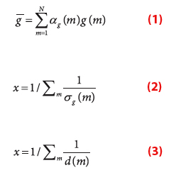
MEOSAR Location Processing
This section presents the location equations used in MEOSAR.
The TOA measurement can be modeled by:
(See inset photo, above right, for all equations)
Going from LEO to MEO has a significant effect on the link budget. The current LEO link margin is estimated to be around 13 decibels. It decreases to about 3 decibels with the use of a MEO space segment. Moreover, each MEO satellite has a wider area of coverage; so, each satellite “sees” more active beacons than a LEO satellite.
An even more important factor is the increased risk of having signal “collisions” (signals from different beacons arriving at a MEOSAR satellite at the same time). This could affect the system capacity, that is, the capability of Cospas-Sarsat to process a number of beacons that are active during the same period. Using spread spectrum for second-generation beacons helps to deal with this issue (see “Second-Generation Beacons under MEOSAR” section). For first-generation beacons, a frequency channelization exists so that the number of beacons that can transmit at the same frequency is limited and regulated by Cospas-Sarsat.
The enhanced system will also be able to use networking in order to exchange TOA/FOA measurements among multiple MEOLUTs. Consequently, a MEOLUT can make additional TOA/FOA measurements including those from satellites that are not tracked or even visible to the MEOLUT. As a general rule, the more measurements available, the more accurate is the location.
This important change in the space segment has to be tested to ensure that the system will still be as robust as it is now. After a proof of concept phase, the MEOSAR transition is currently in the phase of demonstration and evaluation (D&E phase).
The D&E Phase
The goal of the D&E phase is to demonstrate that the system is robust and to evaluate its performance in real conditions. A D&E plan made up of technical and operational tests has been defined to evaluate the technical performance of the system as well as its operational performance. These include the following
Technical tests:
- T-1 – Processing Threshold and System Margin
- T-2 – Impact of Interference
- T-3 – MEOLUT Valid/Complete Message Acquisition
- T-4 – Independent Location Capability
- T-5 – Independent 2D Location Capability for Operational Beacons
- T-6 – MEOSAR System Capacity
- T-7 – Networked MEOLUT Advantage
- T-8 – Combined MEO/GEO Operation Performance
Operational tests:
- O-1 – Potential Time Advantage
- O-2 – Unique Detections by MEOSAR System as Compared to Existing System
- O-3 – Volume of MEOSAR Distress Alert Traffic in the Cospas-Sarsat Ground Segment Network
- O-4 – 406 MHz Alert Data Distribution Procedures
- O-5 – SAR/Galileo Return Link Service
- O-6 – Evaluation of Direct and Indirect Benefits of the MEOSAR System
- O-7 – MEOSAR Alert Data Distribution – Impact on Independent Location Accuracy.
A test coordinator is in charge of defining the planning and collection of results from the participating organizations in the current Cospas-Sarsat program and evaluating the performance of the MEOSAR during the D&E phase.
First-Generation Beacons under MEOSAR
The 406 MHz signal transmitted by distress beacons was originally designed to work with the LEO space segment. (See Table 2.) The location process using the LEO segment is based on Doppler measurements over successive beacon bursts transmitted during a satellite flyby. This means that the signal should have good frequency properties and that this frequency should be stable during an interval of satellite visibility (10–15 minutes).
MEOSAR will still employ the frequency measurement. Nonetheless, in order to have an instantaneous location with enough accuracy, TOA measurements will need to be used as well. However, the 406 MHz signal for first-generation beacons was not designed to have particularly good TOA measurements properties. As the MEOSAR system will be able to provide single-burst location, the frequency stability over consecutive bursts is less important than for LEOSAR.
Another important point is the system link margin. Although the link margin is reduced going from LEO to MEO, the beacons’ antenna pattern diagram must also be taken into account. Most current beacons use simple and robust antennas whose diagram generally exhibits a hole in the zenith region (which is generally the case for monopole or dipole antennas).
This type of antenna fits pretty well in the LEO context where the loss of gain in the zenith region is compensated by the shorter distance to a satellite. Moreover, the time spent by the LEO satellite at high elevation is short.
In the MEO context, satellites are distributed all over the sky. With current antennas, the link margin is severely reduced for satellites at high elevation angles due to the antenna pattern. Besides MEO satellites spend more time at high elevations.
The reduced link margin and the antenna pattern will make it difficult to receive correct data and measurements from a satellite that is at high elevation in relation to a beacon. Depending on the number of co-visible satellites between the station and the beacon, this can affect the possibility of locating a beacon.
Performance of first generation beacons in the MEOSAR system
For first-generation beacons, the independent location accuracy requirement for the MEOSAR system is five kilometers with 95 percent probability, assuming a 98 percent probability of locating a beacon within 10 minutes after its activation. Independent location means that the location is obtained through the use of TOA and FOA measurements only. However, a beacon can transmit its own coordinates by using an embedded GNSS receiver, for example.
These specifications come from those defined for LEO and GEO satellites, taking the more stringent specifications of both types of spacecraft (the independent location accuracy of the LEOSAR system and the fast detection of the GEOSAR system).
Real world performances are currently under evaluation during the D&E test phase.
Second-Generation Beacons under MEOSAR
In parallel with the MEOSAR transition, operational requirements are under definition for a new generation of distress beacons. These second-generation beacons should ensure better system performance and allow for new purposes.
A Cospas-Sarsat publication listed in the Additional Resources section describes the operational requirements for second-generation beacons. Table 3 lists their signal parameters.
One of the remarkable new requirements concerns the increased accuracy standards for the independent location performance:
- 5 kilometers, 95% of the time, within 30 seconds after beacon activation
- 1 kilometers, 95% of the time, within 5 minutes after beacon activation
- 100 meters, 95% of the time, within 30 minutes after beacon activation.
One can notice that the requirement becomes more stringent as the time after activation increases. This supposes the ability of the system to integrate multiple bursts over time to refine the position of the beacon. Nonetheless, the 100-meter requirement is quite challenging to achieve. Even with averaging of successive bursts, this requirement implies an increase in the TOA and/or FOA measurements accuracies.
Another remarkable requirement is the detection probability: at least one valid message should be received during the first 30 seconds with a probability of 99.9 percent. This will require the link budget to be enhanced to meet this performance target.
Complementing such minimum technical performance requirements, new Cospas-Sarsat guidelines have also defined some practical, objective requirements. One of these calls for the ability to transmit an encoded location (obtained by an integrated GNSS receiver, for example) in the beacon message. Another such requirement, which can be combined with the first, is a return link capability.
For example, the Galileo system offers the capability of sending, via the Galileo E1B I/NAV message, an acknowledgment of the reception of an alert to the user. This is an important evolution of the system, which will be able to reassure people that their distress call has been correctly received. The requirement states that the Galileo system should be able to transmit an acknowledgment message within 15 minutes after the reception of the distress message.
Finally, another interesting requirement has been defined: the ability of an ELT beacon to be triggered in flight. The rationale for the requirement is the following: current ELTs incorporate a G-switch that can be triggered automatically when a crash occurs. However, crashes frequently destroy the beacon or the link between the beacon and the antenna, preventing the transmission of a distress alert. Triggering an ELT in flight, based on the appearance of abnormal flight parameters, for example, is a good way to transmit a distress prior to an impending crash and possible destruction of the beacon.
However, this requirement has some consequences for system design. If a beacon is activated on a plane during flight, the often-made assumption that the beacon is static is no longer valid. So, the location algorithm should be adapted to compute a correct location in that particular case.
Second-Generation Beacon Design
In order to meet the new operational requirements, several experts groups have been working to propose specifications for the second generation of Cospas-Sarsat beacons.
The use of repeaters on board satellites allows for completely changing signal waveforms, provided that the legacy and new waveforms together provide a satisfactory multi-access capability. Accordingly, Cospas-Sarsat working groups proposed two approaches:
- A signal structure inspired from first-generation beacon and retro-compatible with SARP instruments to ensure a smooth transition between LEO and MEO systems
- A new signal using direct-sequence spread spectrum (DSSS) to increase significantly the independent location accuracy.
In June 2014, Cospas-Sarsat chose the spread spectrum proposal as the primary solution while keeping the other proposal as a backup option. Motivating this decision was the associated capability of significantly increasing the TOA measurement accuracy. Current first-generation beacons use a signal with a 400bps bit-rate, associated to a Manchester pattern (also known as BOC(1,1) in the GNSS world). The rise time during bit transition is specified to be between 50 and 250 microseconds.
With such a signal, the 1σ Cramer-Rao Lower Bound (CRLB ) for TOA accuracy is between 9 and 20 microseconds at 35dBHz, according to results reported in the articles by N. Bissoli and N. Bissoli et alia listed in the Additional Resources section. Converting these figures into distances, the TOA accuracy would be between 2.7 and 6 kilometers.
With the proposed signal for second-generation beacons, the CRLB for TOA accuracy is now close to 0.5 microsecond (or 150 meters TOA accuracy). Keeping approximately the same FOA performance between first and second generations, the independent location accuracy should be greatly improved. The Figure 8 shows the overall structure of the beacon burst signal.
The second-generation beacon burst has three main parts:
- A preamble composed of a known PRN sequence is used for signal detection at MEOLUT level.
- A “useful message” (202 bits) contains all information needed by SAR responders, such as an identifier that gives information about the beacon and its owner available in a Cospas-Sarsat database. GNSS-encoded positions, if available, can also be transmitted in this part of the burst message to improve the accuracy of the beacon location.
- Finally, bits at the end of the burst are used for error correction, based on a BCH(250,202) code able to correct up to six bit errors.
The transmitted burst has a one-second length and is transmitted periodically. The exact transmission profile is still under discussion because trade-offs have to be made between operational needs and battery capacity of the beacon. The bit rate is 300bps.
The chosen modulation is OQPSK (offset quadrature phase shift keying). As shown in Figure 9, this type of modulation is quite simple and has a near-constant envelope, which is generally an advantage when a signal passes through nonlinear amplification stages.
In the DSSS technique each I and Q channel is multiplied with a known spreading sequence at 38,000 chips/sec. The signal is filtered to limit out of band emissions. Signal spectrum thus occupies a good part of the 100-kilohertz spectrum allocation of the Cospas-Sarsat bandwidth (406.0–406.1 MHz). (See Figure 10)
While primarily employed to improve TOA accuracy, the use of spread spectrum also has advantages for rejecting narrowband interferers. As a consequence, first-generation beacons will not interfere with second-generation beacons and vice versa.
Figures 11 through 14 show theoretical performance of the OQPSK modulation, in terms of detection capability, TOA accuracy, bit error rate, and message error rate.
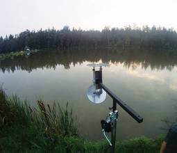
Early Tests of Second-Generation Beacons
In order to evaluate the performance of this new modulation, the United States, France, and Australia have developed transmitters and receivers interfaced with existing ground stations.
On the French side, CNES (Centre National d’Etudes Spatiales) with the help of Thales Alenia Space France, has developed its own transmission and reception chain based on versatile universal software radio peripheral (USRP) equipment that can be used for signal transmission as well as signal reception.
Transmitting the new beacon signal is not a major issue, but receiving signals from at least four parabolic antennas with time synchronization is a bit more complicated. Fortunately, USRPs are perfectly adaptable to this use by synchronizing them in pairs and using an internal GPS for accurate timing of the received signals.
On receiver side, the CNES approach used the USRPs as digitizers and then post-processed the stored signal. The current receiver does not operate in real-time, but this is not an important factor during preliminary evaluation of beacon performance.
On the transmission side, a signal is first generated numerically in software and then played by the USRP in transmission mode. This allows for introducing imperfections in the transmitted signal (phase noise, error in chip rate value, different filtering, etc…) in order to evaluate its impact of the final location performance.
Early testing has already been performed thanks to the test bed developed by CNES. The single burst 2D location performance obtained during the tests was 140 meters at 50 percent probability and 500 meters at 95 percent. (See Figure 15.) This performance will improve as the space segment is growing, allowing for better geometry conditions.
Conclusions and Way Forward
MEOSAR system is currently being deployed along with associated activities to prove that this safety-of-life system will work with a high level of reliability and ensure a smooth transition from the current LEO/GEO system. But we can already say that this evolution from LEO/GEO to MEO/GEO system tends to meet the required improvements in availability and independent location accuracy. The use of second-generation beacons will further dramatically increase this performance, including for moving beacons, opening new services such as in-flight activation and, ultimately, saving more lives.
Additional resources
[1] Bissoli Nicolau, V. (2014), “Performances de détection et de localisation des terminaux “SAR” dans le contexte de transition MEOSAR”, Ph.D. Thesis, Université de Toulouse INP-ENSEEIHT/IRIT, France
[2] Bissoli Nicolau, V. and M. Coulon, Y. Gregoire, T. Calmettes, and J.-Y. Tourneret, (2013a) “Modified Cramer-Rao Lower Bounds for TOA and symbol width estimation. An application to Search And Rescue signals.” IEEE International Conference on Acoustics, Speech and Signal Processing (ICASSP), 26-31 May 2013
[3] Bissoli Nicolau, V., and M. Coulon, Y. Gregoire, T. Calmettes, and J.-Y. Tourneret, (2013b) “Performance of TOA and FOA-based Localization for Cospas-Sarsat Search and Rescue Signals”, IEEE 5th International Workshop on Computational Advances in Multi-Sensor Adaptive Processing (CAMSAP), 15-18 Dec. 2013
[4] Cospas-Sarsat (2013) “Specification for Cospas-Sarsat 406MHz distress beacons”, C/S T.001, Issue 3 – Revision 14, October 2013
[5] Cospas-Sarsat (2013) “Operational requirements for Cospas-Sarsat Second Generation 406MHz Beacons”, C/S G.008, Issue 1 – Revision 2, October 2013
[6] Cospas-Sarsat (2013) “Cospas-Sarsat 406MHz MEOSAR implementation Plan”, C/S R.012, Issue 1 – Revision 9, October 2013
[7] Cospas-Sarsat (2013) “Cospas-Sarsat Demonstration and Evaluation Plan for the 406MHz MEOSAR System”, C/S R.018, Issue 2 – Revision 1, October 2013

