The poor performance of GNSS user equipment in urban canyons in terms of both accuracy and solution availability is a well-known problem that arises where there are tall buildings or narrow streets. This situation is worse in the cross-street direction than in the along-street direction. (See Figure 1.)
The poor performance of GNSS user equipment in urban canyons in terms of both accuracy and solution availability is a well-known problem that arises where there are tall buildings or narrow streets. This situation is worse in the cross-street direction than in the along-street direction. (See Figure 1.)
The accuracy in the cross-street direction can be of great importance to daily life. Numerous street-level applications require sufficient positioning accuracy to perform their functions: for example, detecting the lane in which a vehicle is operating for lane guidance systems and intelligent transportation systems (ITS), location-based advertising (LBA), augmented-reality applications, and step-by-step guidance for the visually impaired or tourists.
A variety of navigation sensors have been used to enhance or augment GNSS to improve navigation performance in highly built-up areas. Road vehicles typically combine GNSS with odometers and map-matching algorithms, while pedestrian navigation users may combine GNSS with cell phone signals, Wi-Fi, and/or dead reckoning using inertial sensors, magnetic compass, and barometric altimeter. A selection of these sensors can help mobile phone users to recognize motion states; consequently, context-adaptive algorithms can be applied to improve the positioning performance.
Although such approaches improve the availability and robustness of a position solution, they do not particularly improve the cross-street accuracy.
In recent years, 3D building models have become more accurate and widely available and are being treated as a new data source for urban navigation that can improve positioning performance in urban canyons. Some investigators are applying 3D city models to enhance map matching and image matching in land vehicle navigation. One line of research employs these models to evaluate GNSS positioning performance with 3D ray tracing or ray intersection techniques. This approach demonstrates the practical potential of shadow matching and is the focus of this article.
GNSS Shadow Matching
The principle of shadow matching employs the “shadows” of GNSS satellite signals to refine the position solution obtained from line-of-sight (LOS) and non-line-of-sight (NLOS) signals. Because of surrounding structures, signals from GNSS satellites may be receivable in some parts of a street, but not others.
In combination with a 3D city model, a GNSS receiver can determine its position to within one of two areas of the street as illustrated in Figure 2. Incorporating other GNSS satellite signals allows users to further refine the position solution, matching the observed signal shadows with the predicted shadowing available from the 3D model.
In previous work, we evaluated and verified the performance of GNSS in urban canyons using 3D city models. Then, we developed a preliminary shadow-matching algorithm that demonstrated the ability to distinguish the pavement from a vehicle lane, and identify the correct side of the street using real-world GPS and GLONASS measurements
Next, we proposed a new scheme that takes into account the effects of satellite signal diffraction and reflection by weighting the scores based on diffraction modelling and the signal-to-noise ratio (SNR). This was shown to improve the navigation solution of geodetic GPS and GLONASS receivers.
Recently, we collected GNSS data collected on a smartphone and processed the data using a shadow-matching algorithm on a PC; however, we still need to conduct a comprehensive analysis of these latest efforts to address the issue of computation efficiency. The series of articles by L. Wang et alia and P. Groves et alia, cited in the Additional Resources section near the end of this article, describe these initial shadow-matching investigations.
This article presents a significant development of shadow matching — a smartphone-based shadow-matching system that works in real time. This work is motivated by two concerns: accommodating the low-grade antenna and the low-computational power typical of smartphones.
As for the first concern, most potential applications of shadow matching use consumer-grade GNSS user equipment, whereas previous shadow matching algorithms were mainly tested using geodetic GNSS receivers. Moreover, consumer-grade GNSS receivers normally cost much less and can be subject to worse signal reception, more severe multipath reception, and stronger non-line of sight (NLOS) reception due to the low gain and linear polarization of consumer-grade GNSS antennas. These differences can degrade shadow-matching performance.
Regarding our second motivation for the current focus, smartphones and personal navigation devices (PND) normally have much less computational capability in comparison with a desktop computer or laptop, whereas the existing algorithm has only been run on personal computers. Its computational efficiency has not previously been tested. Thus, optimization of the shadow-matching technique to make it suitable for smartphone-grade devices is worth investigation.
Consequently, this article proposes and implements a smartphone-based system, aiming at meters-level cross-street accuracy in urban canyons. It will also assess the real-time positioning performance of shadow matching on a smartphone.
The following section summarizes the design of the real-time shadow-matching system and presents its optimizations in pre-processing to determine the elevation and azimuth boundary of the buildings in a test area. We then describe the details of application development on the phone’s Android operating system.
Next comes an assessment of real-time experiments applying various criteria to compare the performance of the conventional GNSS navigation solution with the shadow-matching system solution. Finally we address the feasibility of larger scale implementation and end with conclusions drawn from the results of this investigation.
System Design & Optimization for Real-Time Apps
Let’s start by explaining key design choices of the smartphone-based shadow-matching system, including overall architecture, the modified shadow-matching algorithm, and improvements essential to real-time efficiency.
System Architecture Design. In a full implementation of a shadow-matching system, a server interacts with the smartphone user. The smartphone first sends a positioning request with an initial GNSS position to the server. The server then gathers the building boundary data that assists in shadow-matching based on the user’s initial position solution and sends them back to the user. Finally, the smartphone performs the shadow-matching algorithm and acquires a revised positioning solution. The overall architecture of the shadow-matching system is illustrated in Figure 3.
In terms of algorithm design, shadow matching has two phases — the offline phase (the preparation step) and the online phase (the real-time positioning) — which are executed in four steps, represented by the red boxes in Figure 4.
The off-line phase is conducted to generate a grid of building boundaries. At the beginning of the online phase, the search area is defined for the shadow-matching position solution, using the initial GNSS position.
In the second step, satellite visibility at each grid position is predicted using the building boundaries generated from the 3D city model. After that, the difference between prediction and observation is evaluated using a scoring scheme, providing a score for each grid point in the search area.
Finally, the shadow-matching positioning solution is generated by a modified k-nearest-neighbors algorithm, which averages the grid points with the highest scores. A full implementation would also incorporate context detection to determine whether the user is in an indoor, urban, or open environment (See the article by P. Groves et alia, 2013b). In that case, the shadow-matching algorithm would only be implemented in urban contexts.
Let’s look at each of the shadow-matching steps in more detail.
Step 0: Generate a Grid of Building Boundaries (Off-Line Phase). In the off-line phase, building boundaries are generated for each point on a grid of outdoor locations. The boundaries are presented from a GNSS user’s perspective, with the building edges determined for each azimuth (from 0 to 360 degrees) as a series of elevation angles. The results from this step show where the building edges are located within an azimuth-elevation sky plot.
Figure 5 shows an example of a building boundary computed from a candidate user location. Once the building boundary has been computed, it may be stored and reused in the online phase to predict satellite visibility by simply comparing the elevation of a satellite with the elevation of the building boundary at the same azimuth. We developed a software toolkit in C++ for generating the grid of building boundaries from a 3D city model.
Step 1: Determine the Search Area for Candidate Positions from the Building Boundaries on a Grid. The first step of the shadow-matching algorithm requires an initial GNSS position. In an urban environment, GNSS accuracy is often poor.. Therefore, it is important to minimize the effects of NLOS reception and multipath interference on the position solution.
Other available positioning methods (e.g., Wi-Fi or cell network solutions) may be introduced in this step when the blockage is too great in urban canyons for GNSS to provide a position fix or when GNSS gives less accurate positioning than other available positioning methods.
The first step defines the search area in which the candidate positions are located for the shadow-matching position solution. A search area is defined based on the initial position. A simple implementation would be to draw a fixed-radius circle centered at the initialized position, but more advanced algorithms can be developed to use the knowledge of satellite geometry to optimize the search area.
For instance, if the initial position is generated using a conventional GNSS solution, the signal geometry — and hence the positioning accuracy — will be much better along the direction of the street than at right angles to the street. This is because an urban canyon affects the geometry of the available GNSS signals. As explained earlier, signals with cross-street lines of sight are much more likely to be blocked by buildings than signals with lines of sight running along the street.
Therefore, the conventional GNSS solution has a lower accuracy across the street and a higher accuracy down the street, which is complementary to the shadow-matching algorithm. Thus, the down-street component of a conventional GNSS solution can be used as a reference to define the search area and generate candidate user positions with a greater range of possibilities in the cross-street direction.
Figure 1 illustrates this phenomenon by showing the two green mobile phones on either side of the initial GNSS solution of the user phone, with the green area representing the search area centered at the initial position. A more advanced shadow-matching algorithm would vary the size of its search area based on an assessment of the quality of the received satellite signals.
Step 2: Predict Satellite Visibility at Each Candidate Position. In the second step, performed at each candidate position, each satellite’s elevation is compared with the building boundary elevation at the same azimuth. The satellite is predicted to be visible if the satellite is above the building boundary. With pre-computed building boundaries, this step can be computationally efficient.
Step 3: Satellite Visibility Scoring. In the third step, the similarity between predictions and observations of the satellite visibility is evaluated. The candidate positions with the better matches will then be weighted higher in the shadow-matching positioning solution.
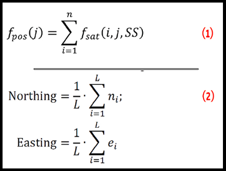
Calculating a score for a candidate position takes place in two stages. First, each satellite above the elevation mask angle is given a score, calculated based on the predicted and observed visibility. Second, the position-scoring function evaluates the overall degree of match between predicted and observed satellite visibility for each possible user position. This is illustrated in Equation (1).
Equation (1) (see inset photo, above right)
where fpos(j) is the position score for grid point j and fsat(i, j, SS) is the score of satellite i at grid point j using the scoring scheme SS, which defines a score based on predicted and observed satellite visibility, while n is the number of satellites above the elevation mask angle.
By the end of this step, each candidate position should have a score to represent the degree to which it matches the observed satellite visibility, and thus how likely it is that each candidate position is close to the true location.
Various scoring schemes can be applied at this stage. Figure 6 shows the two-by-two scoring scheme used in this work. This scheme only considers direct LOS signals. Other schemes can take into account diffraction and reflection effects. The difference between various scoring schemes is outside the scope of this article. More details can be found in the paper by L. Wang et alia (2013a).
Step 4: Positioning Using Scores at Candidate Positions. The last step of the shadow-matching algorithm generates a position solution using the scores from each candidate position. Shadow matching uses the pattern-matching positioning method (Groves, 2013a) cited in Additional Resources. As the process of Wi-Fi fingerprinting is similar to this process, the algorithms used in Wi-Fi fingerprinting may be investigated for their potential implementation in shadow matching. Potential algorithms include, but are not limited to, k-weighted nearest neighbors, the Bayesian inference received signal strength (RSS) location method, and the particle filter.
In the work described in this article, we used a method similar to k-nearest neighbors to estimate the location, averaging the grid positions with the highest scores. In the current scoring system, scores take integer values. Therefore, several grid points typically share the highest score. The points in the grid with highest scores are regarded as nearest neighbors.
For L nearest neighbors, the location estimate is obtained using (2):
Equation (2) (see inset photo, above right)
where ni and ei are, respectively, the northing and easting coordinates of the ith high-scoring candidate positions. Note that L varies from epoch to epoch depending on how many candidate positions share the highest score.
Improving Real-Time Efficiency
The main strategy for improving real-time efficiency involves pre-computing the building boundaries and storing these on a server. From the perspective of mobile devices, this approach trades time and computing power for a one-off processing requirement at the server side. Specifically, this is achieved by representing the 3D model in a specially designed form: building boundaries at each candidate position.
The logic behind this strategy arises from the fact that the vast amount of data in a 3D city model is not of direct interest to our shadow-matching algorithm. The algorithm only needs to know where the edges of the buildings are located from a user’s perspective. So, our method only extracts the building boundaries at each candidate position from the 3D model.
This approach saves real time computational load, because individual mobile devices do not need to compute the building boundaries on the fly. Instead, they can simply request pre-computed building boundaries at a certain range of locations, or cache a desired region.
Using stored building boundaries, this method requires fewer than 50 comparison and addition operations to calculate an overall shadow-matching score for one candidate position using signals from two GNSS constellations. Therefore, shadow matching may be performed in real time on a mobile device with several hundred candidate positions, where necessary.
The optimized process in the off-line phase can be broken into four steps. To begin, a horizontal grid of points with three-meter spacing, covering the 3D city model area, is generated. The height is set to be 1.5 meters above the terrain height measured in the 3D city model, reflecting the assumed location of a handheld smartphone.
Next, a pre-processing step eliminates indoor points from the generated grid in the first step, because the current shadow-matching algorithm is designed to work outdoors. Outdoor points are distinguished from indoor ones by testing whether the elevation angle of the sky at each azimuth is 90 degrees. Further details of the algorithms testing line-of-sight visibility can be found in a previous paper (Wang et al., 2012).
The third step eliminates from the search area any buildings that are unlikely to block satellite signals, based on checks of their relative location from the candidate position of interest. Finally, the lowest elevation angle for a visible sky at each azimuth is tested to determine the building boundary at each outdoor candidate position. Figure 7 outlines this process of generating building boundaries.
In order to improve the efficiency of the off-line phase, in the third step only buildings that are close to the candidate position and in the direction of interest are tested. In this step we test in every azimuth (1, 2, …, 360 degrees) direction separately. For example, when we are computing building boundaries at azimuth 10 degree, we don’t need to consider buildings that are located at 190 degree because those buildings cannot block a signal from azimuth 10 degree. Figure 8 illustrates this search area, noting that the parameters marked on the figure are manually selected based on knowledge of the 3D city model used in this work. Appropriate changes should be made if using another type of city model.
Without optimization described in this section, it takes an estimated six days to perform the process of calculating a grid of candidate positions with three-meter spacing across a 500-by-500–meter area, using a computer with a CPU speed of 2.67 gigahertz. After optimization, the time required to generate building boundaries at the same grid of points was reduced to 10 hours, a 93 percent reduction in time compared to the original algorithm for PC-based shadow matching.
Developing Apps for Android Devices
We developed an application (app) that runs on the Android operating system. The smartphone used in this work receives both GPS and GLONASS satellites with assisted-GPS (A-GPS or AGPS) capability. It runs on a Linux-based operating system primarily for mobile devices. It is one of the most common smartphone systems available for purchase today.
Additional details of the smartphone and the software tools used in this work may be found in the Manufacturers section near the end of this article. In this section we will focus on the development of the smartphone app itself.
The app was developed in Java and built on the Standard Android platform 4.0.3, using the Android application programming interface (API) to retrieve information from the GNSS chip in the smartphone. In this implementation, the building boundary data is stored on the phone’s secure digital (SD) memory card. The Android operating system listens to the real-time GNSS messages from the GNSS chip, interprets GNSS information from them, and provides the information to app developers through the API. The public interface GpsStatus. Listener outputs, in real time, the information provided by the GNSS chip, and contains a number of useful attributes, including azimuth, elevation, and SNR of GPS and GLONASS satellites in view. The latest location determined by the GNSS chip is also output by the public interface LocationListener.
This data feeds into the shadow-matching positioning engine, together with the building boundary data stored on the SD card. The positioning engine then computes user position based on the conventional GNSS solution. Finally, the positioning results are displayed on maps. Figure 9 provides a flowchart of the app.
Assessing App Performance in Field Experiments
To evaluate the performance of a real time shadow matching system on smartphones, experiments were conducted in central London, England. The following section describes the 3D city model, the test sites, and the configuration of the shadow-matching system. Recorded GNSS data is then processed using an identical algorithm to that in the real-time system The design and results of a typical example of the real-time experiments are compared with those of conventional GNSS positioning.
Experimental Settings. We used a 3D city model of the Aldgate area of central London. The model has a high level of detail and decimeter-level accuracy. Figure 10 shows part of the city model used in the experiments.
Four locations with diverse road conditions were selected on Fenchurch Street, a built-up urban area. Accompanying photos taken at the street show the urban environments. Two of the sites, named G1 and R1, were located at a “T” junction between Fenchurch Street and Fenchurch Buildings Road. The other two sites, named G2 and R2, were selected between junctions on Fenchurch Street.
G1 and R1 are located on opposite sides of the street, enabling the new system to also be tested for its ability to distinguish the correct side of the street. The same layout applies to G2 and R2. All sites were selected on the footpath (sidewalk) close to traffic lanes.
Figure 11 shows an aerial view of the city model and a satellite image, illustrating the settings of the four experimental sites. The truth model is set using the 3D city model. The slight offset between the city model and the satellite image is caused by the geometric distortions of the satellite images.
Before the experiment, in the off-line phase of this work, we generated a grid with three-meter spacing. Indoor points were then eliminated and building boundaries determined at outdoor points, as described previously. The building boundaries were stored in a specially defined format in a database and pre-loaded on the smartphone used in this experiment.
Real-time shadow-matching positioning was performed with a five-second interval on the smartphone. The researcher stood at each location for six minutes collecting both GPS and GLONASS observations. Real time satellite visibility information and conventional GNSS positioning results were recorded at one-second intervals for later analysis.
Real-Time Experiment. We conducted the shadow-matching positioning experiment in real time and found that the typical processing time took one to two seconds.
Figure 12 shows the shadow-matching app being used at site G2 during the real-time experiment. As the application is a prototype of the real-time shadow-matching system, both the conventional GNSS solution of the smartphone GNSS chip and the positioning solution of the new system are displayed to the researcher for a real-time comparison. The blue points are the conventional GNSS solutions, while the red points represent the solutions of the new system.
The true location of the experimenter at G2 can be found in Figure 11. The blue points on the screen in Figure 12 indicate that the conventional solutions are on the wrong side of the street and distributed sparsely in the across-street direction compared with the solutions of the new app. The shadow-matching real-time solutions (red points) are distributed more consistently in the across-street direction, on the correct side of the street. This is in line with the expected benefits of the new system, which gives better across-street accuracy.
Analysis of algorithm scoring results. In real time, a 40-meter radius circle, centered at the conventional GNSS positioning solution provided by the smartphone GNSS chip, is used to generate candidate positions defining the search region for the new shadow-matching technique. The pre-calculated candidate grid of building boundaries (i.e., the off-line phase database) is loaded at this stage. At each observation epoch, a comparison is made between the predicted and observed satellite visibility, and the scoring scheme is applied accordingly.
To illustrate the distribution of scores at the grid points, Figure 13 displays examples of the score maps at each experimental location. The colored dots represent the candidate positions obtained and assessed by the shadow-matching app. The scale on the right-hand side of the graphs represents the score obtained for each candidate position in the shadow-matching algorithm, with higher scores representing a higher confidence level that the user is at this location. The true location of the experimental site is shown by a black cross in each color map.
The results in Figure 13 clearly demonstrate that the shadow-matching algorithm is sensitive to changes in the cross-street direction, but less sensitive in the down-street direction. This is in line with expectations and complements conventional GNSS positioning, which is generally more precise in the down-street direction in urban areas due to the signal geometry.
As seen in Figure 13, some spaces between buildings fall within the search area. These are the colored dots surrounded by white areas. However, the highest scoring points are predominantly in the correct street. From this figure we can also infer that, in most cases, the highest score areas (dark red) appear on the correct side of the street. However, the high scores do not always appear at the expected area, mainly due to non-line-of-sight signal reception. Applying different scoring matrices may reduce the effect imposed by NLOS receptions, but this is outside the scope of this article.
Performance Comparison with Conventional GNSS Positioning. To assess the performance of real-time shadow matching against the conventional GNSS positioning solution, we transformed the position errors from local coordinates (Northing and Easting) to the along-street and across-street directions. Figure 14 shows the positioning results of the conventional GNSS navigation solution from the smartphone GNSS chip, compared with the shadow-matching positioning results, expressed as errors in the across-street direction.
The results show that, in most cases, the shadow matching solution outperforms the conventional GNSS positioning solution. The shadow matching solution has improved the conventional positioning error, in the across-street direction, from typically 10–40 meters to within 5 meters in most epochs. In the case of G2 (the upper-right panel in Figure 14), the shadow-matching solution accuracy is better than two meters in most epochs.
On the right side of each sub-figure in the figure, the position error distribution is compared between the shadow matching solution and the conventional solution. These results show that shadow matching improves the positioning accuracy, reducing the average error to less than five meters on average in each case.
In order to evaluate the performance across all of the epochs, we conducted a statistical analysis using an indicator, mean absolute deviation (MAD). Comparisons of the MADs at each site, seen in Figure 15, show the improvements of shadow matching over conventional GNSS positioning.
Each set of colored bars shows the mean across-street positioning error using the conventional and shadow matching algorithms, respectively. The data cover a six-minute observation period, during which the constellation geometry changed slowly; so, the results are highly correlated, temporally, allowing consistency of the system to be evaluated.
The results indicate that across-street positioning performance of shadow matching is significantly better than the conventional GNSS positioning solution. The shadow-matching positioning algorithm reduced the average cross-street error by 36.9, 77.6, 90.8, and 71.3 percent for G1, G2, R1, and R2, respectively.
The new positioning system reduces the cross-street error from 14.81 meters in the conventional solution to 3.33 meters in the new system, averaged over all four experimental sites. This is a 77.5 percent reduction of cross-street positioning errors on average. The RMS difference shows that the consistency of the shadow-matching solution also outperforms the conventional solution.
We conducted further statistical comparisons to assess the positioning performance in terms of success rate over six minutes, and the results are shown in Figure 16. As the street is about 10 meters wide, a positioning accuracy of less than 5 meters is considered good enough to determine correctly which side of the street the users is on, while a positioning accuracy better than 2 meters should be good enough to distinguish the footpath from a traffic lane.
Averaged over the four experimental sites, shadow matching produced a 54.4 percent success rate for correctly determining the side of the street, significantly improved from the success rate of 20.9 percent for the conventional solution. The success rate for distinguishing the footpath from a traffic lane is 25.6 percent for shadow matching, also considerably increased from 7.7 percent for the conventional GNSS positioning.
Figure 17 shows the positioning results of the new system compared with the conventional GNSS solution as displayed in the satellite view of Google Earth. The blue dots represent the locations of the conventional GNSS solution, recorded in real time. The purple dots denote the positioning solutions provided by the new system. The green and red pushpins represent the true location of the site in each case.
These results indicate that, typically, the new system gives solutions more consistent with each other in the cross-street direction and better accuracy compared to the conventional solution. However, the conventional solution is more accurate in the along-street direction, in line with expectations.
The smartphone-based shadow-matching positioning system is a suitable complement to conventional GNSS positioning. As shadow matching improves the cross-street positioning significantly, it shows a high potential to be combined with conventional GNSS and other possible techniques for better overall performance.
Notably, the selection of a suitable grid spacing of building boundaries influences the performance and speed of the shadow matching system. The three-meter spacing of the current implementation of the real-time shadow-matching system already produces a significant performance improvement in comparison with conventional GNSS positioning. A grid with two-meter, one-meter, or even denser spacing can potentially be applied.
In our research described here, we also tested a one-meter grid spacing, which provided an improved performance of five percent in terms of reduction of mean error averaged over the four sites. However, using the grid with one-meter spacing requires roughly nine times more computational time in comparison with using a three-meter grid spacing.
Clearly, there is a trade-off between the accuracy of the shadow matching system and the running time. The reason we ultimately used a three-meter grid in the real-time system is that it gives the best compromise between performance and speed.
Potential for Larger-Scale Implementation
This section assesses the feasibility of deploying the system for broader usage.
Availability of 3D City Models and Satellite Information. The shadow-matching system depends on 3D or 2.5D city models to improve positioning; so, the availability of the models is important. Fortunately, an increasing number of 3D city models are available through the Internet. A few commercial examples are mentioned in the Manufacturers section alongside an option for free/inexpensive models.
By relying on the building boundaries from the city models, the shadow matching system only requires information on which satellites are being tracked rather than actually processing pseudorange or carrier phase measurements. This is provided by most consumer-grade GNSS receivers on a regular basis in NMEA sentences using data from GNSS navigation messages.. With an SNR message also regularly available through NMEA sentences, shadow matching can provide even more reliable performance. Fortunately, various phone operating systems provide an API for developers to get this information in real time.
Data Storage and Transfer Requirements. Shadow matching requires knowledge of the building boundaries in order to work. Thus, the building boundaries database should be transferred to the user device on the fly or pre-downloaded (Groves et alia, 2012b).
Building boundaries with one-degree resolution in azimuth at a grid point requires about 300 bytes of storage, without compression. With a 3 meter • 3 meter grid, a one kilometer-long, 20-meter wide street would contain 2,222 grid points, which would require 651 kilobytes of data storage. If similarities between adjacent azimuths were exploited, substantial data compression should be possible — perhaps up to a factor of 10.
A four gigabyte flash drive could store up to 62,920 kilometers of road network. The Great London metropolitan area contains about 15,000 kilometers of road. Thus, it may be practical to preload the building boundaries onto a smartphone.
An alternate method would be to transfer the data over the mobile network as required. On a 100-meter long 20-meter wide street, only 222 grid points are needed for shadow matching, which requires 65 kB of data. Transferring this would take less than a second using the 3G mobile phone network with a normal data plan.
Thus, in practice, it is feasible to implement the shadow-matching system on a smartphone, a PND, or other consumer-grade navigation device.
Demand from Applications. Meters-level across-street accuracy in urban areas benefits a number of existing location-based services and creates new applications. For example, vehicle lane detection is feasible with meters-level across-street accuracy. Although lane guidance systems are now common for in-car navigation systems, they can only suggest a correct lane to a driver, without knowledge of which lane the car is currently operating on.
A lane detection system may enable a lane guidance system to know the current lane of operating and thus better guides a driver to the correct lane and sends warning when the car is not operating on the correct lane. Similarly, intelligent transportation systems (ITS) may use this technique to give directions to individual vehicles so as to maximize traffic flow and give priority to emergency vehicles.
In situations where crossing the road takes considerable effort for pedestrians, location-based advertising (LBA) systems could use this technique to target the most suitable customers on the same side of the street. Some augmented-reality games may enhance the experience of the players through more accurate positioning.
Perhaps most importantly, step-by-step guidance for the visually impaired and for tourists requires high positioning accuracy in urban areas in order to work. Navigation in mountainous regions could also benefit from this system when a digital elevation model (DEM) is available.
Conclusions
A new smartphone-based shadow matching system, based on knowledge derived from 3D models of buildings, has been designed. The new system is optimized to improve computational efficiency to account for the low processing power and limited storage on smartphones.
The system does not require real-time rendering of 3D scenes or any additional hardware, making it power-efficient and cost-effective. An increasing number of smartphones have multi-core processors, enabling parallel processing techniques to be exploited for improved efficiency of shadow matching. In the future, the system can also be expanded to work with Galileo and BeiDou (Compass), with potentially improved performance.
The shadow matching system can be implemented on a smartphone, a PND, or other consumer-grade navigation device, as part of an intelligent positioning system, whereby the cross-street position is determined mainly by shadow matching and the along-street position mainly by conventional ranging-based GNSS positioning. Multi-epoch kinematic positioning using shadow matching could also be investigated to exploit knowledge from different epochs for better positioning performance.
Other technologies, such as Wi-Fi positioning or inertial and pressure sensors, could be added to improve the overall positioning performance. In the long term, shadow matching could form part of a new generation of multi-sensor, integrated navigation systems alongside techniques such as environmental feature matching, low-cost array-based inertial measurement units, opportunistic radio navigation, and context adaptivity (described in the article by P. Groves et alia, 2013b).
Acknowledgments
The primary author gratefully acknowledges UCL Ph.D. student Kimon Voutsis for his assistance in the raw data collection, and UCL Ph.D. student Hira Virdee for his proof-reading and helpful comments. This author is very grateful to all members of UCL’s Space Geodesy & Navigation Laboratory (SGNL) for their discussions and comments over the course of his doctoral research. The University College London Engineering Faculty Scholarship Scheme and the Chinese Scholarship Council jointly funded this research. This article is based on a paper presented at the ION GNSS+ 2013 conference.
Additional Resources
[1] Bourdeau, A. and M. Sahmoudi, “Tight Integration of GNSS and a 3D City Model for Robust Positioning in Urban Canyons,” ION GNSS, Nashville, Tennessee, 2012
[2] Bradbury, J., “Prediction of Urban GNSS Availability and Signal Degradation Using Virtual Reality City Models,” Proceedings of the 20th International Technical Meeting of the Satellite Division of The Institute of Navigation (ION GNSS 2007), Fort Worth, Texas, 2007
[3] Bradbury, J., and M. Ziebart, P. A. Cross, P. Boulton, and A. Read, “ Code Multipath Modelling in the Urban Environment Using Large Virtual Reality City Models: Determining the Local Environment,” The Journal of Navigation, Vol. 60, pp. 95-105, 2007
[4] Cappelle, C., and M. El Badaoui El Najjar, F. Charpillet, and D. Pormski, “Virtual 3D City Model for Navigation in Urban Areas,” Journal of Intelligent and Robotic Systems, 2011
[5] Costa, E., “Simulation of the Effects of Different Urban Environments on GPS Performance Using Digital Elevation Models and Building Databases,” Transactions on Intelligent Transportation Systems, Vol. 12, pp. 819-829, 2011
[6] Groves, P. D. (2013a), Principles of GNSS, Inertial, and Multisensor Integrated Navigation Systems (2nd edition), Boston, London, Artech House
[7] Groves, P. D., “Shadow Matching: A New GNSS Positioning Technique for Urban Canyons,” The Journal of Navigation, Vol. 64, pp. 417-430, 2011
[8] Groves, P. D., and Z. Jiang, L. Wang, and M. Ziebart (2012a), “Intelligent Urban Positioning using Multi-Constellation GNSS with 3D Mapping and NLOS Signal Detection,” ION GNSS 2012, Nashville, Tennessee
[9] Groves, P. D., and H. Martin, K. Voutsis, D. Walter, and L. Wang (2013b), “Context Detection, Categorization and Connectivity for Advanced Adaptive Integrated Navigation,” ION GNSS+ 2013, Nashville, TN
[10] Groves, P. D., and L. Wang and M. Ziebart (2012b), “Shadow Matching Improved GNSS Accuracy in Urban Canyons,” GPS World, Vol. 23, pp. 14-29, February 2012
[11] Ji, S., and W. Chen, X. Ding, Y. Chen, C. Zhao, and C. Hu, “Potential Benefits of GPS/GLONASS/GALILEO Integration in an Urban Canyon – Hong Kong,” The Journal of Navigation, Vol. 63, pp. 681-693, 2010
[12] Kim, H. I., and K. D. Park and H. S. Lee, “Development and Validation of an Integrated GNSS Simulator using 3D Spatial Information,” Journal of the Korean Society of Surveying Geodesy Photogrammetry and Cartography, Vol. 27, pp. 659-667, 2009
[13] Kleijer, F., and D. Odijk and E. Verbree, “Prediction of GNSS Availability and Accuracy in Urban Environments – Case Study Schiphol Airport,” Chapter 23 of Location Based Services and TeleCartography II In: REHRL, G. G. A. K. (ed.). Springer-Verlag, Berlin Heidelberg, 2009
[14] Misra, P., and P. Enge, Global Positioning System: Signals, Measurements, and Performance Revised Second Edition, Ganga-Jamuna Press, 2010
[15] Obst, M., and S. Bauer and G. Wanielik, “Urban Multipath Detection and Mitigation with Dynamic 3D Maps for Reliable Land Vehicle Localization,” Position Location and Navigation Symposium (PLANS), IEEE/ION, 2012
[16] Peyraud, S., and D. Betaille, s. Renault, M. Ortiz, F. Mougel, D. Meizel, and F. Peyret, “About Non-Line-Of-Sight Satellite Detection and Exclusion in a 3D Map-Aided Localization Algorithm,” Sensors, Vol. 13, pp. 829-847, 2013
[17] Peyret, F., and D. Betaille and F. Mougel, PEYRET, F., “Non-Line-Of-Sight GNSS Signal Detection using an On-Board 3D Model of Buildings,” 11th International Conference on ITS Telecommunications (ITST), 2011
[18] Pinana-Diaz, C., and R. Toledo-Moreo, F. Toledo-Moreo, and A. Skarmeta, “A Two-Layers Based Approach of an Enhanced-Map for Urban Positioning Support,” Sensors, Vol. 12, pp. 14508-14524, 2012
[19] Suh, Y., and R. Shibasaki, “Evaluation of Satellite-Based Navigation Services in Complex Urban Environments using a Three-Dimensional GIS,” IEICE Transactions on Communications, E90-B, pp. 1816-1825, 2007
[20] Tiberius, C., and E. Verbree, “GNSS Positioning Accuracy and Availability within Location Based Services: The Advantages of Combined GPS-Galileo Positioning,” NaviTec, 2004, Noordwijk, The Netherlands
[21] Wang, L., and P. D. Groves and M. Ziebart, “GNSS Shadow Matching Using A 3D Model of London,” European Navigation Conference, Grange Tower Bridge, London, 2011
[22] Wang, L., and P. D. Groves and M. K. Ziebart (2012a), “GNSS Shadow Matching: Improving Urban Positioning Accuracy Using a 3D City Model with Optimized Visibility Prediction Scoring,” ION GNSS 2012, Nashville, TN
[23] Wang, L., and P. D. Groves and M. K. Ziebart (2012b), “Multi-Constellation GNSS Performance Evaluation for Urban Canyons Using Large Virtual Reality City Models,” The Journal of Navigation, Vol. 65, pp. 459-476
[24] Wang, L., and P. D. Groves and M. K. Ziebart (2013a), “GNSS Shadow Matching: Improving Urban Positioning Accuracy Using a 3D City Model with Optimized Visibility Prediction Scoring,” Journal of The Institute of Navigation, Vol. 60
[25] Wang, L., and P. D. Groves and M. K. Ziebart (2013b),”Shadow Matching: Improving Smartphone GNSS Positioning in Urban Environments,” China Satellite Navigation Conference (CSNC) 2013 Proceedings, Springer
[26] Yozevitch, R. B. M., and H. Levy, “Breaking the 1 Meter Accuracy Bound in Commercial GNSS Devices,” IEEE 27th Convention of Electrical & Electronics Engineers in Israel (IEEEI), 2012

