Geospatial Fusion on the Fly
(The following online version is text only. To see graphs, charts, and images, download the article pdf above.)
The development of GNSS worldwide has fundamentally changed the way many professions conduct their business.
Arguably, the profession of surveying has been most affected because surveyors, at their core, are experts at measurement. For millennia they have been the first to take advantage of any new technology that improves their ability to locate objects accurately.
Until recently, the landmass of Alaska has had little in the way of either control networks or boundary surveys. This is why GNSS has been a godsend for our company, Tanana Chiefs Conference (TCC).
TCC is a nonprofit corporation that primarily consolidates medical and social services for 42 small Alaska Native villages located in remote, mostly roadless regions of the interior. However, we also employ a small group of professional surveyors whose ongoing task is to lay out boundaries for the Alaska Native Claims Settlement Act (ANCSA) village and regional corporations.
These surveys, covering thousands of square miles each summer, are part of a much larger 35-year effort by the United States Bureau of Land Management to delineate government and tribal land claims throughout the state.
In the days before GNSS, an ANCSA project required a major expedition each year to hire surveyors, assemble the equipment and supplies, and mobilize for a survey based in some distant village. It took up to six crews of surveyors and helpers, an office staff of five or six, and a DC-3 full of tripods, total stations, and chainsaws.
Today, 15 years later and with sophisticated GNSS equipment, we get by with a lot less. The results are more accurate and trustworthy, and only a single person is needed to run the surveying office, which consists of a laptop computer.
Villages without Boundaries
Although GNSS has solved many difficulties of large-scale remote surveys, it hasn’t been nearly as helpful at the local level. The villages where our crews are based each field season are scattered over 235,000 square miles — a region slightly smaller than Texas.
These villages generally have a few boundary problems of their own and always a subdivision or two that needs to be surveyed. In remote Alaska, flying in a survey crew is very expensive, and few villages can afford it, so little has gotten done over the years in the way of addressing village boundaries. To be helpful, our company generally donates a week of what we call VTS (village triage surveying) to the various places we visit.
Unfortunately, once we get there, the local work is time consuming because traditional field methods are needed for much of the control and design work. For example, Athabascan villages are communal in nature and rarely contain fences that divide housing and possessions. A good deal of time is needed to locate everything in sight and figure out who owns what. Moreover, original boundary markers are scarce, and hours are spent digging up old axles and snowmobile parts in an effort to uncover the few remaining survey monuments.
It occurred to us that aerial photography might be a worthwhile tool to make our efforts more useful to the locals in the short time we had. For example, if a subdivision could be designed not from a weeklong topographic survey, but from a table-sized, high-resolution orthophotograph, it would save a lot of time and trouble.
Most villages in interior Alaska have been aerially photographed at one time or another, but timely orthophotography is rare, and the resolution of even the best photos — about one pixel per foot — is less accurate than needed. To distinguish the incredible variety of objects scattered throughout a village, something in the range of two to three centimeters per pixel (about half the width of a soda can) would be more useful.
Although new photogrammetric techniques make this high resolution achievable, commissioning new low-altitude photography and the associated expedition – a very expensive undertaking — is not an option for these distant villages.
Off the Shelf Solutions?
We were naïve enough to think that, with a little experimentation, we could achieve these results with off-the-shelf consumer equipment. After all, we had an available helicopter that was used for U.S. Bureau of Land Management (BLM) work, and high-resolution, 10- to 20-megapixel consumer cameras were just now appearing on the marketplace.
It sounded simple enough, why not rectify a series of hi-res, low-altitude digital photos taken from our helicopter?
However, spending a little time investigating this idea only demonstrated how little we knew about photogrammetry. The process wasn’t nearly as easy as we thought. We almost abandoned the idea, but, once again, GNSS saved the day and provided the key to a solution that made everything work.
Digital aerial photography cameras are precise and complex instruments and cost upwards of $500,000. Their large 23×23-centimeter charge-coupled device (CCD) array must be tightly calibrated in conjunction with a fixed camera lens to compute distortion values unique to each camera.
Based on this calibration, software algorithms can then warp each pixel exactly the right amount to remove the lens distortion, which, in turn, allows for pixel matching and the creation of accurate digital terrain models (DTMs) from stereo pairs of georeferenced photos. The calibration repeatability in these cameras is so high that accurate orthophoto mosaics can be assembled using relatively few photo control points on the ground.
A consumer-grade camera, however, even a good one, is not designed for this tight a tolerance. Although such cameras’ lens characteristics can be calibrated, the repeatability is diminished as even a slight change in alignment— say, due to a tiny machining error in a lens bayonet mount — can change the calibration values each time the camera is used.
As important as the camera is the software. Dedicated, full-featured photogrammetric suites are used to rectify digital aerial photos—but these start at a major-league price of $50,000.
Then we came up with a possible alternative.
In recent years relatively inexpensive photo-modeling software has appeared in the marketplace. This software is capable of making accurate 3D models of anything that can be photographed — something as small as a Neolithic human footprint preserved in shale or as large as the ornate façade of a medieval church. It is also commonly used to reconstruct automobile accident scenes, creating 3D computer models for forensic evidence.
In spite of the smaller scale of such subjects, the photo-modeling software shares the same mathematical principles used by dedicated photogrammetry suites. So we explored this idea. Some searching on the World Wide Web led to the discovery of a 3D photo-modeling software used primarily by architects and archeologists.
Although created as companion software to be bundled with an imaging total station, the software can also serve as a stand-alone product that can manipulate any set of controlled stereo pairs — a pair of images containing a minimum number of corresponding photo control points with accurate x, y, and z coordinates. The program is designed to work with tiny, circular photo targets, which can be automatically registered with an order of magnitude greater precision than the human eye.
The technique can produce remarkably accurate results, but, as always, there is no free lunch. To compensate for the looser reliability of lens calibration on small format digital cameras, the software requires a denser network of photo control targets. The total station with which the photo modeling software is usually paired, for example, can populate its digital photos with scores of accurate data measurements for use by the software.
This photo control requirement has relegated photo-modeling software to working in small confined areas. Theoretically, however, it should also work on a larger scale if sufficient photo control is available.
So, it was tempting to think that, with the eight dual-frequency GPS/GLONASS receivers we normally employ in BLM surveys and a few rented four-wheelers, the requisite photo control could be readily established on a village scale. (I imagined survey crews scooting around on ATVs, scattering small aerial targets in their wake like Frisbees, each measured to sub-centimeter accuracy using on-the-fly GNSS!)
Upriver for a Real Test
The Alaska summer is short. We barely had time to fly a test mission with the helicopter and work out altitude, camera settings, and target sizes before we needed to get under way.
Our first real trial took place at Huslia, a village on the Koyukuk River about 10 days by barge from Fairbanks. This river flows from the south flank of the Arctic Divide through broad, glacially carved valleys in the rugged Endicott Mountains of Alaska’s Central Brooks Range.
The Huslia village council had requested a new subdivision survey because about half the residents lived in a still-unsurveyed portion of town. In this congested central village space, subdivision lots must be custom designed using polygonal shapes to conform to each tenant’s use and occupancy. The polygon lots are separated by a chaotic layout of existing roads and trails.
This was exactly the type of situation we had in mind for aerial surveying, but the timing was rather tight. Only a week earlier we had ordered the software from Nick Russill, managing director of TerraDat UK Ltd., a geophysical consulting and contracting company based in Cardiff, Wales. Nick had generously volunteered to help us with the Huslia project because the photo-modeling software has a learning curve, and the giga-pixel, square-kilometer aerial survey would be pushing this modeling software into uncharted territory.
The software package was delayed in transit, however; so, at the last minute Nick changed his travel plans, jumped on a flight to Alaska, and hand-delivered the software.
He arrived by helicopter, intercepting our survey barge, Seloohge, on the Koyukuk River about a day’s voyage below the village. Talk about customer support!
The following morning, as the barge neared Huslia, the crews crowded into the Seloohge’s pilot boat and sped away with a stack of homemade targets that consisted of several dozen 18 inch diameter white vinyl disks packed with beach sand. At the village it didn’t take long to rent a few ATVs from which to scatter the targets, and, by the time we arrived with the big boat, about two hours later, all the requisite photo control was in place.
The targets were roughly distributed in open areas at 80–100-meter spacing throughout the site. As soon as the targets were placed, they were measured to sub-centimeter accuracy using dual baseline, stop-and-go GPS techniques, consuming another one to two hours.
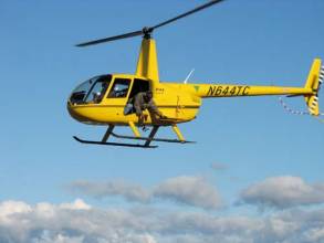
Soon thereafter, Nick and I found ourselves hovering 1,200 feet above the village in a helicopter with the rear door removed. Compared to traditional aerial photography, the technique was definitely low-tech. The camera and stabilizing gyro were suspended from a bungee cord looped around the neck of the photographer, who then leaned out the door, pointed the camera straight down with an outstretched hand, and took photos every second or so as the aircraft slowly flew parallel strips across the village.
Although we soon learned that an onboard guidance system utilizing preprogrammed routes would be more efficient and provide for consistent coverage, this first effort relied entirely on the pilot’s ability to fly parallel routes based on observed ground features, a task more difficult than it sounds. The resolution of the imaging at Huslia topped out at six centimeters per pixel but subsequent improvements in our camera handling techniques improved this to three centimeters per pixel.
The digital camera was then calibrated using a companion program of the photo-modeling software. The program automatically computed the lens distortion parameters by analyzing a series of photographs taken from various angles of a target grid, an E-sized plot of a .dxf image file (included with the software) that we had carefully taped to the galley window of the barge.
Next, choosing 14 photos from our overflight of the village that provided the best overlapping coverage, Nick guided me through the stereo pair registration, measurement of control and tie points, and the creation of a DTM. The process is fairly straightforward once a host of various keyboard shortcuts are mastered.
The software maintains a point data file which can be quickly populated with the adjusted x, y, and z coordinates of the aerial targets. Stereo pairs, selected from a set of two photos that contain roughly 60 percent common overlap, are oriented by the identification of a minimum of four aerial targets visible in both images, plus an additional four to six tie points. Tie points are distinct, uncoordinated points, such as a white food bowl in a dog yard, which can be positively identified on each photograph.
The software automatically matches pixels at a selected tie point and will either accept it or reject it based on the certainty of the match in the corresponding photo. As each pair of tie points are identified, the accuracy of all the points can be examined with a network bundle adjustment routine.
The creation of a digital terrain model, a three-dimensional surface model of the overlapping area contained within the stereo pair, is a little more problematic as it relies on user input to identify breakline positions that are required to assist the software in making accurate pixel matching and elevation determinations.
Breaklines, which are drawn as polylines, are placed where sudden breaks in terrain exist, such as a ditch at the edge of a road or where the ground meets the wall of a house. Photogrammetrists rely on stereo imaging displays for this time-consuming process which manages to be both tedious and frustrating. Fortunately, for those of us using a laptop without a stereo display, the modeling software contains a useful workaround by supplying an auto-correlater that assists the operator with the exact placement of each corresponding polyline vertex.
By late afternoon we had a product: a mosaic of orthophotos held together with cellophane tape that was then proudly displayed on a big table in front of a lively crowd at the village council office. The resolution of the mosaic was such that an observer could easily pick out the smallest objects, and the villagers had no trouble identifying each other’s possessions as we sketched in new lot lines. Visible power poles and overhead wires helped with creation of utility easements.
After dinner, the marked-up photo mosaic was imaged in computer-aided drafting software, and vectors were created to match the layout. Point coordinates were identified for each lot corner position in the subdivision, exported into GPS receivers and, the following day, using real-time kinematic (RTK) techniques our survey crews set the monuments that defined the new subdivision.
The approximate accuracy of the resulting boundary monuments produced 1:50,000 closures, basically the sub-centimeter accuracy one would expect from dual-frequency, differential GNSS measurements. Note that the accuracy of the surveyed monumentation is independent of the accuracy of the aerial photo. In only two days we had accomplished what used to take a week of hard work, and at the same time we created a
very useful product for future land planning in Huslia village.
Low-Cost Accuracy
Of all the things we learned from this experiment, what surprised me the most was the accuracy of the orthophoto. A bundle adjustment of the control and tie points generated error ellipses well within the subpixel range, a fact verified by quality control checks comparing GNSS measured features with corresponding photo locations.
Without doubt it is the dense network of precisely measured control points that allows for this exactness, by constraining the photography like tacks on a board. A field-generated, high-resolution orthophoto of this accuracy could be a powerful new tool for surveyors.
The speed, precision, and reliability of GNSS-measured target networks, combined with the development of high-resolution small-format cameras and well-designed photo modeling software, now makes this possible.
What began as an idea to make pro bono work in the villages more efficient is now opening doors for revenue-generating enterprises such as accurate terrain modeling of mining, development and environmental sites, and low-cost, high-resolution, confined area photo-mapping for projects such as road intersections, construction sites, and siting and layout of resorts.
This is just one example of how the development of GNSS, surveying, and the technology of measurement – and the village of Huslia — have benefited in more ways than had been anticipated.
By