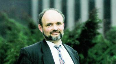
Pat Fenton: GNSS from the Outside In
Patrick Fenton’s career as the guiding mind behind the design of six generations of breakthrough GNSS receiver technologies began the moment he realized his hobby — computer programming — might end the need for surveyors to spend long evenings reducing and verifying the data they collected each day.
Patrick Fenton’s career as the guiding mind behind the design of six generations of breakthrough GNSS receiver technologies began the moment he realized his hobby — computer programming — might end the need for surveyors to spend long evenings reducing and verifying the data they collected each day.
It was the summer of 1981. Fresh out of the University of Calgary’s survey engineering program, Fenton was enjoying a taste of what he’d envisioned would be a “professional outdoor career” as a rookie land surveyor for ShellTech Surveys, a now defunct division of Shell Canada.
“We would spend all day turning the angles and measuring for a road project,” he said. “Then, evenings we would spend hours reducing the data and making sure it was all correct. I was able to hop on the computer and get that done for the crew very quickly.”
Fenton’s inspired effort ended his work outdoors. “They told me to stay in the office and develop the software,” he recalled. “From then on I worked on processing the data and developing equipment that would make their jobs easier.”
When the oil crunch hit, ShellTech was sold in January 1982 and became Nortech Surveys Ltd. Fenton worked on a number of high-tech survey systems for the oil exploration industry, including INS, microwave ranging, and GPS. He became software manager of a Nortech subsidiary, Norstar Instruments.
“At the time, there wasn’t a suitable GNSS instrument on the market that met the needs of Nortech; so, the management decided that we had the talent to jump into the survey instrument business,” Fenton said. “We did create a very nice product; however, we lacked knowledge in high quality manufacturing. Each one we built was a little bit different.”
A Better Mouse Trap
NovAtel, then a giant in Canada’s cell phone industry, acquired the NorStar division in 1989.
“The combination of skills at NovAtel was exactly what was needed for our GPS products, that is RF, software and production engineers, DSP chip designers, and marketing experience,” Fenton said. “At NovAtel, we completely redesigned the receiver from the antenna down.”
At about the same time, Fenton hit upon an insight that led to an industry first: true sub-meter pseudorange positioning capability.
“I realized that the signal processing design and tracking loops within the GNSS receivers of that day were optimized for maximal signal power to signal processing complexity ratio,” he explained. “They were not optimized for range or carrier phase tracking accuracy — the elements driving position accuracy. It was during this period that I came up with the Narrow Correlator concept.”
His invention, commercialized into the GPS1001 receiver in 1991, was five times more precise than the previous technology. It received the Better Mouse Trap Award that year from the Institute of Navigation (ION).
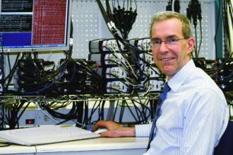
Today Fenton is vice-president and chief technology officer (CTO) for NovAtel, which has become a leading provider of GPS and augmentation components and subsystems designed for rapid integration into an endless variety of high precision, commercial applications.
At the tender age of 49, he holds 15 patents and has authored more than 20 technical articles for the ION. So significant are his contributions to the evolution of GNSS that his peers have recognized him with the ION Satellite Division’s highest honor: the Johannes Kepler Award.
Fenton is also known for projects that have significantly improved receiver capability to allow reliable positioning and precise navigation even in obstructed environments where GPS alone doesn’t work. Marine, mining, precision agriculture, and surveying and mapping are among the applications benefiting from such advancements.
On the Fast Track
For example, he has spent several years leading a small team that is integrating inertial measurement units with NovAtel’s GNSS receivers. The results of their success using digital terrain modeling (DTM) techniques to improve precise position output availability are showcased during telecasts of NASCAR and IndyCar races.
“Our challenge was to provide Sportvision a continuous stream of time-tagged position and velocity measurements from each race car,” Fenton said. “Sportvision uses this information to annotate the TV camera image stream with details such as the driver’s name, speed, and lap time while the race is underway.”
Sounds simple enough. But NASCAR tracks presented formidable challenges for radio frequency coverage, the lifeblood of GNSS technology.
“In addition to lots of steep bleachers there are cat walks around and over the track,” Fenton explained. “Probably the worst obstacle was the steel mesh catch fence that completely surrounds and overhangs the track. When the cars are up against the wall, more than half the sky is blocked by the catch fence.”
No sky, no satellite coverage. Not only that, but the tracks are very short. Laps can take as little as 15 seconds. “When a car is halfway around the track, it has blocked the other half of the sky. In this case, as a result, we could never lock in a satellite for more than 10 seconds.”
Using a DTM of the NASCAR track, Fenton’s team was able to constrain a car’s position. “This algorithm acted like an additional satellite and improved the availability substantially,” he explained. “But it wasn’t until we added integrated IMUs [inertial measurements units] that we were able to deliver 100 percent position and velocity availability.”
Fenton’s hallmark is a knack for finding and integrating technologies that drive powerful new applications. During the mid-1990s, as he rose from chief engineer to director of research and development, he was instrumental in NovAtel’s acquisition and commercialization of the MEDLL (Multipath Estimation Delay Lock Loop) technology, licensed from Delft University. WAAS, the U.S. Federal Aviation Administration’s Wide Area Augmentation System, and the European Geostationary Navigation Overlay Service (EGNOS) use it.
This powerful combination of scientific chops and market acumen earned Fenton a vice presidency in 1997 and the additional title of CTO in 2003. He was appointed to NovAtel’s board of directors in 2005.
The company’s latest generation OEMV series of GNSS receivers, released last year, illustrates the exponential changes in core technology that occur between versions. NovAtel’s “system on a chip” now has more than four million gates, almost eight times as many as its predecessor.
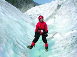
Fenton, who grew up in Canada’s capitol (Ottawa) has retained his zest for the outdoors including a passion for photography. He met his wife Tanis through her brother, a skiing buddy. They have three children; two in college and one in high school, and the entire family takes full advantage of Alberta’s rich recreational opportunities.
But even in the remotest glacier field, Fenton never completely loses touch with GNSS. Each winter he and a group of friends rent a backcountry hut and helicopter in for a week of alpine skiing. “Four times in our lives we’ve been up in a whiteout,” Fenton said. “We were able to navigate back to the hut with GPS.”
Fenton’s coordinates:
N51 06’ 59” W114 02’ 18”
COMPASS POINTS
Engineering Specialties
System conceptualization, GNSS receiver design and signal processing, multipath mitigation techniques, and firmware development.
His Compass Points
• Home and family: wife Tanis and three children, household activities, weekend trips, summer vacations, extended family, and friends
• Career: applied technology, mentoring, teamwork, business relationships, learning, and change
• Hobbies: photography, and outdoor activities
Favorite Equation
This formula is a derivative of the Central Limits Theorem. It’s a simple formula but I use it all the time to estimate expected signal-to-noise ratio levels at the output of hardware correlators at various stages of designing GNSS receivers.
GNSS “Aha” Moment
In the summer of 1985, I started developing position processing software from data Nortech had collected from their various survey operations. I realized that I could make a significant contribution.
First Significant GNSS Achievement
I came up with the Narrow Correlator concept. This technique made for a five-fold improvement in pseudo range accuracy, leading the way to reliable sub-meter positions.
GNSS Mentor
Probably the single person that I’ve learned the most from in GNSS over the years is Dr. A.J. Van Dierendonck. He was the chief scientist with Stanford Telecommunications Inc. where we were sourcing GPS receiver channels for the first GPS product I was involved with in 1986. He has been a technical consultant with us, periodically, for nearly 20 years.
GNSS Event that Most Signifies That GNSS had “Arrived”
I think the first Gulf war with all the publicity and TV images of the smart weapons provided a huge boost to the popularity and awareness of GNSS. Before that time, I always had to explain what GPS was. After that time, everyone seemed to have a good appreciation for what GNSS was.
Influences of Engineering on His Daily Non-Work Life
My engineering mind is always churning. For example, over the last couple of years my wife and I built an energy-efficient house. I was heavily involved with all the engineering aspects of that; producing all the CAD construction drawings, design of all the mechanical systems including the in-floor geo-thermal heating system, and the networks for phone and internet connectivity to all the rooms.
Popular Notions about GNSS That Most Annoy
The notion that GNSS will work deep indoors, under ground, or under water – perhaps for oil exploration at the bottom of a drill tip or for diving. If you can’t pick up FM radio, then most likely your GPS won’t work.
Favorite Non-GNSS Activities
Winter: skiing, snowboarding, alpine touring
Spring/Summer/Fall: cycling, canoeing, camping, sailing, fly fishing
All seasons: photography
What’s Next
There are several possibilities. The first would be multi-constellation, multi-frequency GNSS. This is where a single receiver tracks multiple satellite constellations (GPS, Galileo, GLONASS, etc.) and provides a blended robust position solution. The second may come from time of arrival (TOA) positioning of cellular phone tower signals. The density of cell phone towers is continuing to increase. At a certain point, the use of TOA processing of cell signals will rival consumer GPS for the large urban and indoor markets.