Satellite Development Advances as GPS Survives Budget Cuts, LightSquared
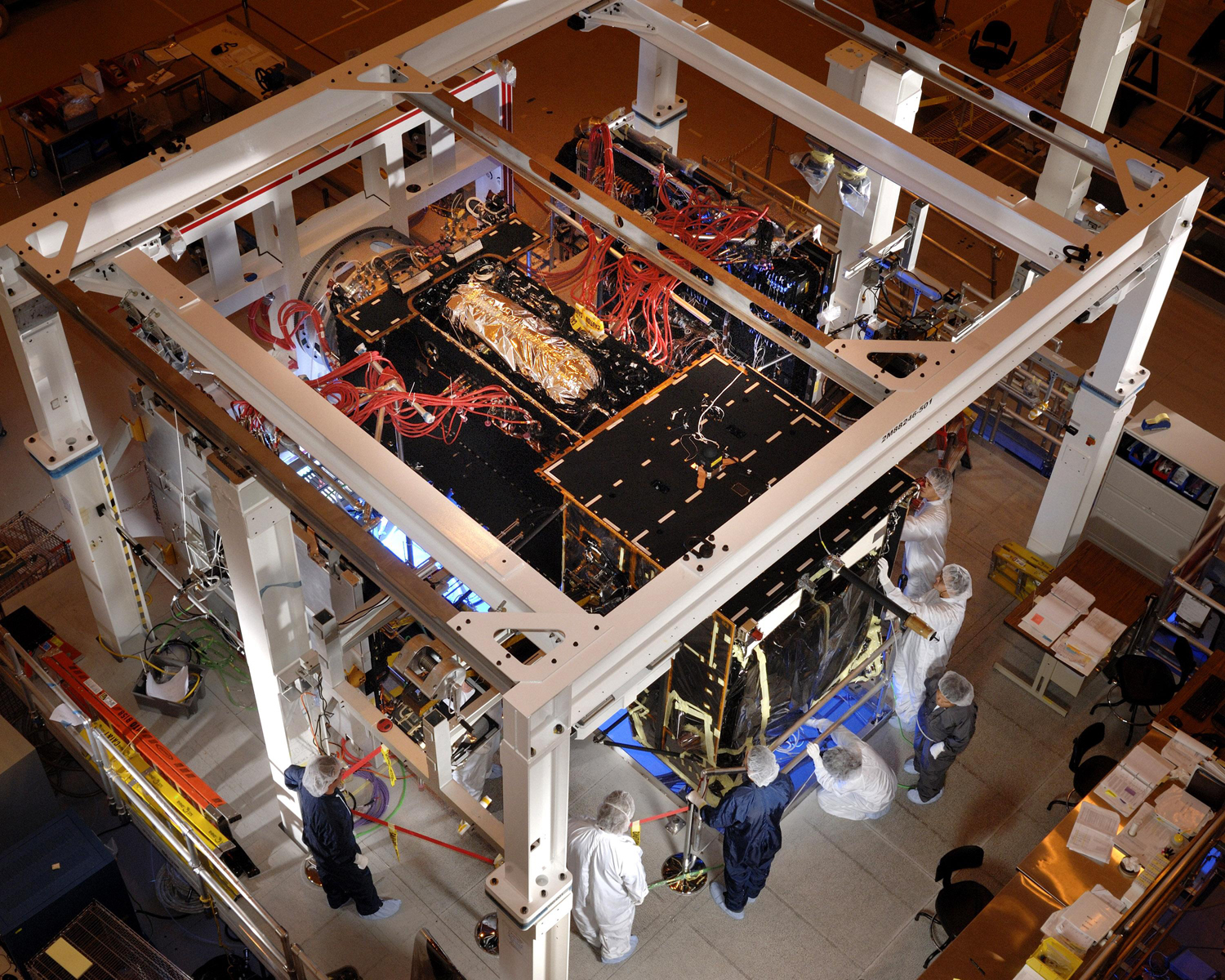
New GPS III Test Chamber (Lockheed Martin photo)The United States GPS program is without doubt the elder statesman of GNSS, but it has had some close calls recently.
At the 2012 Munich Satellite Navigation Summit in March, a high-level Department of Transportation offical and the head of the Air Force GPS Directorate hailed continuing progress on the Global Positioning System’s third-generation satellite development and next-generation control segment (OCX), while apparently escaping — relatively unscathed — the dual perils of Congressional budget cuts and LightSquared interference.
By Inside GNSS