March 26, 2010
UPDATE: On March 24, 2010, Elizabeth Cannon was appointed president of the University of Calgary. Scheduled to take office on July 1, she is the first woman to hold the position.
If anyone can synchronize micro-satellites to fly in formation, it’s Elizabeth Cannon – geomatics engineer extraordinaire, leading researcher, technology transfer virtuoso, dean of the University of Calgary’s Schulich School of Engineering in Canada’s engineering capital.
And, not least, a mentor to many — including a number of bright women engineering students who will benefit from the strategies Cannon is developing to increase their numbers in science and industry.
Cannon’s trademark is taking an inexpensive device that already exists and finding a new use for it that raises the bar for accuracy in navigation. For example, Cannon’s imaginative use of equipment available on most new cars — odometers, gyros, and the steering angle sensor—produced a patent-pending system that can be used to automatically avoid collisions and improve control of vehicle stability
At 45, she has transformed technologies in ways that reach almost everyone.
From the moment she first encountered GPS as a summer student at Calgary’s Nortech Surveys in 1983, Cannon was hooked on the concept of using signals from space to precisely measure things on the ground. Since then, her self-described “addiction to accuracy” has spurred development of novel satellite-based positioning methods, software, and applications including indoor location, automobile positioning systems, precision farming, and remote sensing.
“Ten years ago, I don’t think I would have predicted where we are today,” Cannon says. “What’s exciting is you’ve got the GPS signals being enhanced, new signals being transmitted from space via GALILEO and the enhancement of GLONASS, and now the Chinese are developing a system.”
Inventor
Cannon’s ability to move discoveries from lab to market has resulted in two patents (and one more pending) plus a state-of-the-art product line that includes coauthoring nine GPS software packages used by more than 200 agencies worldwide.
Commercialized by a university subsidiary, University Technologies International (UTI), these innovations already have returned significant licensing income to the University. What’s more, many of Cannon’s graduate students are recognized as co-inventors and share in the financial benefits from licensing fees.
Three recent projects provide a window on the scope of Cannon’s research enterprise
Precise vehicle positioning system. Cannon’s team used GPS/INS with built-in onboard sensors on a passenger vehicle to achieve centimeter accuracies in urban and suburban areas.
“This a major challenge given the tough environment and the need for lower-cost sensors,” she says. “We have developed a real-time system that can deliver centimeter-level accuracies with GPS outages up to 10-20 seconds.”
Cannon’s imaginative use of built-in equipment (odometers, gyros, and the steering angle sensor) produced a patent-pending system that has been transferred to industry for market development.
Assisted GPS Under Various Aiding Scenarios. At the other end of the spectrum, Cannon’s group has looked at assisted GPS, in which various siding parameters were provided to a high sensitivity GPS receiver, in order to determine the impact of different parameters on acquisition and tracking performance.
“What really counts is being able to track signals in weak signal environments, around trees or indoors,” Cannon says. “We are looking at information that can be provided to your GPS unit through the cellular network.”
Simulator and field tests are being performed using hardware support from SiRF Technology, a prominent GNSS innovator in creating technologies that confer “location awareness” or “location intelligence” to a wide range of consumer products.
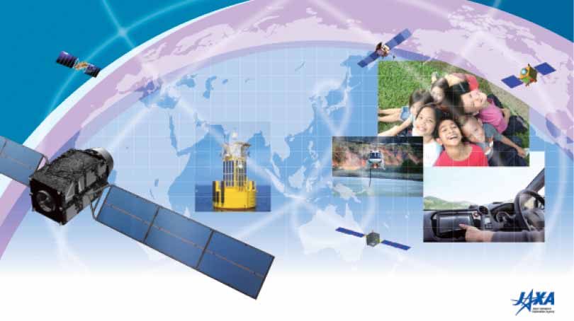
Formation Flying of Micro-satellites Using GPS. Initially, Cannon’s lab used their software simulation environment to test the use of carrier phase GPS for inter-satellite positioning and formation flying. Now the focus has shifted to using a hardware simulator to develop algorithms and test the system under various operating conditions.
“You want to have a certain configuration with a certain spacing from one another, to the centimeter or sub-centimeter level,” Cannon explains. “The next ultimate goal is to use it in space.”
When that breakthrough is achieved, the way will open for new applications that can be expected to drive GNSS-assisted technologies to even higher levels of precision and accuracy. Possible benefits include improved methods of tracking global climate change. How long will it take? “We’re probably a couple of years away,” Cannon says.
The work is being done in conjunction with the Space Flight Laboratory at the University of Toronto’s Institute for Aerospace Studies.
A Natural Scientist
Born to parents with science backgrounds, Cannon’s affinity for mathematics and the sciences was unfettered from the start. As a junior high student in Charlottetown, the seaside capital of Prince Edward Island, Cannon knew science was her calling.
When she discovered GPS, Cannon’s course was set. She quickly earned three degrees in geomatics engineering at the University of Calgary. Her international reputation as a top GPS trainer and researcher was cemented long before she defended her doctoral thesis.
Change Agent
To date, Cannon’s impact on life as we know it encompasses four broad areas extending well beyond her contributions to satellite navigation research and development. In broad brush strokes, she is recognized internationally for
-
Helping shape the research agenda through directorships and memberships in key corporate, research and scientific organizations.
-
Spearheading progress at the international level through her leadership roles in the U.S.-based Institute of Navigation (ION).
-
Developing successful strategies for increasing the number of women at all levels of academics and industry, and
-
Communicating the value of research, and of science and technology in general, to society.
In fact, the list of honors recognizing the excellence of Cannon’s research, teaching, and service covers three pages, single-spaced, in eleven-point type.
She is a Fellow of the Royal Society of Canada and the Canadian Academy of Engineering, She was listed as one of Canada’s “Top 40 Under 40” in 1998. She is the Schulich School of Engineering’s first female dean.
But one award in particular signals the history-making caliber of Cannon’s work: in 2001 she became the first woman to receive the Institute of Navigation’s most prestigious honor, the Johannes Kepler Award.
A Willing Role Model
Less than five percent of Canada’s engineering students were women when Cannon earned her first bachelor’s degree in mathematics at Acadia University in 1982. Though the percentage of women studying engineering has grown to 18 percent in Canada, equalizing the gender balance remains a top priority.
In the United States, the National Science Foundation’s updates on the status of women lump engineers together with all women in science, including the physical, mathematical, computer, environmental, life, and social sciences and psychology. Even with the inclusion of a number of disciplines where women are better represented, the most recent figures show women holding just 28 percent of U.S. faculty positions and 18 percent of full professor posts for engineering and science combined.
These comparatively low numbers are prompting U.S. lawmakers to consider whether cultural factors are continuing to dampen the advancement of women in these areas. In Russia and China, for example, women comprise a much higher percentage of engineers and scientists.
”When you go into a field, you are there because you want to be there, but others look at you and expect you to be a role model,” Cannon says. It is an expectation that she has embraced as passionately – and pragmatically – as she does the pursuit of accuracy in navigation.
“Making sure young women know what the opportunities are and helping them make informed choices is what it’s about,” she says. “I enjoy that, because it’s a way of giving back.”
A Life in Balance
If multi-tasking were an Olympic sport, Cannon would be the odds-on favorite for the gold medal. How does she manage?
“It’s a balancing act,” she acknowledges. “I’m very fortunate that my husband is extremely supportive. We’re really a team, and we’ve tried to integrate our children into what we do.”
Looking ahead, Cannon sees no end to the stream of innovation arising from satellite navigation.
“GPS is still magical in that it keeps us intrigued,” she says. “The demands on technology to provide accuracy anywhere, at low cost, under a huge range of operating conditions, presents never-ending challenges to research and creativity.”
Cannon’s Coordinates
Latitude = 51° 04’ 47.83343”
Longitude = 114° 08’ 01.85354”
Height = 1118.592 m
COMPASS POINTS
Engineering Specialties
Algorithm and software development, system integration
Her Compass Points
- My husband, Gérard Lachapelle, who also works in GNSS
- Our two kids – Sara and René
- My network of wonderful women friends
- Time alone to reflect and recharge
Favorite Equation
The Kalman filter update equation:
x+ = x– + K(z – Hx–)
where
x+ state vector after update
x– predicted state vector
K Kalman gain matrix
z measurement vector
H design matrix
When She Fell in Love with GNSS
1984. I was working on some of the early GPS carrier phase software developed by Ben Remondi and Clyde Goad at NGS. This was a great experience as so few people were working at this level of accuracy at that time. There was lots to learn and you had a sense that GPS was poised to become something really big!
GNSS Event That Most Signified That GNSS Has “Arrived”
When my friends brag about having GPS in their Blackberries!
Engineering Mentor
My mother, who was a science graduate and became a high school math and science teacher.
Influences of Engineering on Her Non-work Life
Being at a university where I am dean of engineering, it actually consumes my life!
Popular Notions About GNSS That Most Annoy
That it works anywhere to a centimeter!
Favorite Non-GNSS Activities
Running and reading.
What is the next “big” thing?
New signals in space that will drive performance and new applications.
Human Engineering is a regular feature that highlights some of the personalities behind the technologies, products, and programs of the GNSS community. We welcome readers’ recommendations for future profiles. Contact Glen Gibbons, gl**@********ss.com.
By