
Guest contributor Marius Gheorghe of Ideal Aerosmith Inc. explores time-tested techniques and exclusive insights for effective inertial sensor and system testing.
Inertial sensors and systems play a vital role in applications ranging from navigation to robotics, aerospace, automotive and consumer products. Testing these sensors and systems is essential for several reasons, including but not limited to calibration, performance verification, environmental factors, reliability, integration with systems, safety and regulatory compliance. Testing them can therefore be very complex and becomes a discipline in and of itself.
This article explores a few aspects related to inertial sensor and system testing.
Test Fixtures
One of the key elements in inertial testing is the test fixture. Test fixtures adapt the units under test (UUT) mounting features to the predefined hole patterns of the test tables, typically a two-inch or 50 mm grid. Requirements for the test fixtures vary with the application.
For example, when testing inertial measurement units (IMU) on two-axis rate and position tables, the alignment of the IMU input reference axes [1] to the tabletop’s reference axes is important. When performing centrifugal testing, locating the UUT center of measurement becomes important.
Successful test fixture design involves observing some dos and don’ts. Do use geometric dimensioning and tolerancing (GD&T) for the critical features. Do specify an appropriate flatness and parallelism of the two main mating surfaces. Do specify precision dowel pins for mounting alignment. Don’t forget the cable management. Don’t forget the ease of use. Don’t over-design.
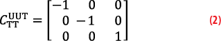
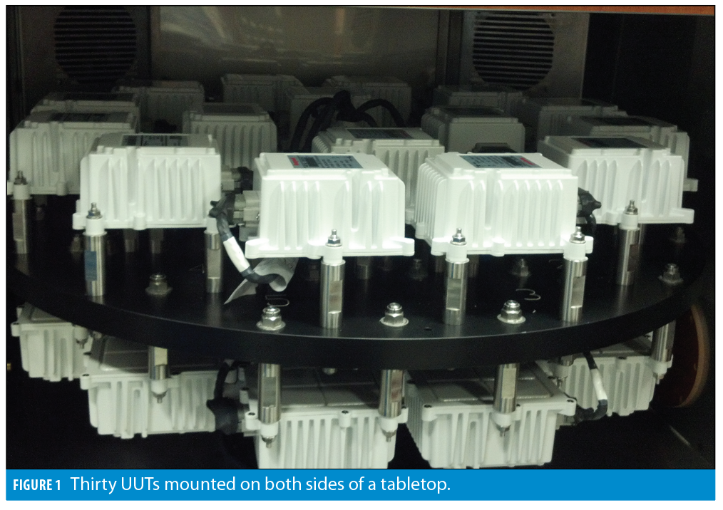
Testing multiple UUTs simultaneously brings up additional considerations for test fixtures, especially when the UUTs are mounted in six different orientations, as shown in Figure 1. In this case, the different UUT orientations can be tackled mathematically with rotation matrices. For setups like this one, these 3×3 matrices are populated with just ±1s and 0s. For example, Equation 1 rotates the tabletop stimuli sTT by 180° around the z-axis, using the

to transform them into the stimuli seen by the UUT:


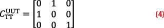
It is equally easy to use these matrices to convert from a right-handed reference system to a left-handed one:
Designing test fixtures may look deceptively easy. Aspects such as incorrect design (e.g., one that uses incorrect angle compounding for canted fixtures), under-design (e.g., one that lacks alignment features), over-design (e.g., one that uses a too-thick base plate, unnecessarily increasing the thermal mass), or non-ergonomic design (e.g., binds when installing onto or removing from the tabletop, or it is hard to access) may arise when the designer lacks knowledge specific to the inertial testing domain.
Ideal Aerosmith Inc. provides comprehensive test fixture design services in conjunction with the inertial test equipment and inertial lab services.
Test Profiles
Usually, UUTs are submitted to test profiles to calibrate them or verify their performance meets acceptance criteria. In either case, they are exposed to inertial stimuli (acceleration or rates), and their output is recorded. In some cases, the output is compared against thresholds, while in others, it is used in conjunction with the applied stimuli to compute specific parameters.
Individual sensors and systems are typically described using a mathematical formula called an error or a correction model, depending on whether the formula describes how the sensor performs in real life or how it needs to be corrected to approach the idealized one.
A famous error model is the one provided for the linear single-axis accelerometer in [2]. Oddly enough, the model for the linear accelerometer comprises more than 10 nonlinear terms, allowing for a lot more, depending on the user’s appetite. (Note the reproduction of this equation is omitted here due to copyright restrictions.)
However, a much simpler error model for a linear triaxial accelerometer is given in factorized form:

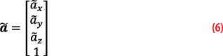
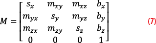
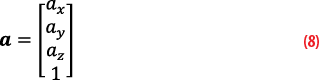
The ã… are the corrupted sensor outputs; the a… are the true stimuli applied to each axis; the s… are the true scale factors (including any errors); the m… are the combined misalignments and sensor nonorthogonalities; the b…are the biases.
Reducing the error model to a factorized form allows its parameters to be computed using linear algebra.
This model does not show stochastic terms such as noise, as stochastic behavior is typically corrected using Kalman filters.
Test profiles must be designed adequately so all parameters of the desired error model are observable. For this reason, at the Ideal Aerosmith Inertial Laboratory, we typically specify 24-point tumble tests for triaxial accelerometers. An in-depth observability study is presented in [3]. The higher order terms from the single-axis linear accelerometer mentioned in [2] require testing at very high accelerations to ensure observability, something typically achievable only with centrifuges.
And then, there is the aspect of differentiating various error sources that are often blended in a single coefficient. In some cases, disentangling them requires special test steps, while in others, as show in [4], mathematical methods are employed.
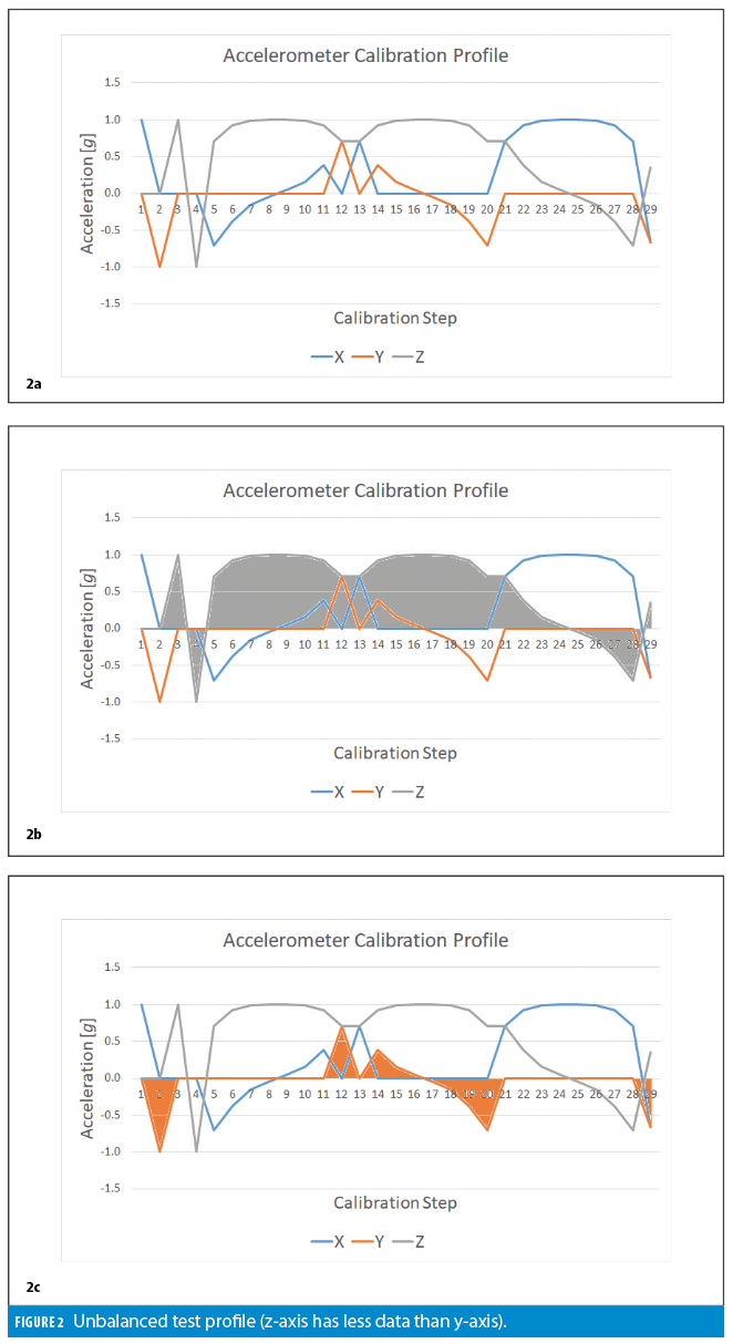
Test profiles must also be designed so they provide a comparable number of samples at each stimulus level for each UUT axis and for all UUTs. The example shown in Figure 2 illustrates an unbalanced profile.
When in doubt, ensure the area under the test profile envelope is approximately the same for all axes.
Productivity Enhancement Tips
It should come as no surprise that reducing the test time per device results in increased productivity.
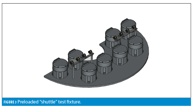
One of the obvious solutions is to test multiple UUTs at the same time (Figure 1). However, this concept should be complemented with a poka-yoke design to eliminate operator errors, and by employing hotel or shuttle configurations to reduce the change-over time (Figure 3). Hotel or shuttle fixtures can be preloaded while a batch of other UUTs is tested and can be swapped in more efficiently than the individual UUTs.
Swap UUTs the smart way, not the hard way.
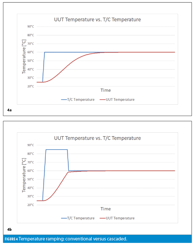
Another aspect is UUTs spend a lot of time transitioning between temperatures and soaking at temperature. Therefore, optimizing these aspects also can lead to reduced test times. One solution is to use cascaded temperature control, which can expedite the temperature ramping of the UUTs. Figure 4a shows a conventional temperature ramping, while Figure 4b demonstrates a cascaded ramping.
If the UUTs have embedded temperature sensors, conduct a thermal study to determine the time needed for the internal UUT temperature to stabilize at each temperature point used for testing. In some cases, thermal soak times can be substantially reduced by identifying the points of diminished returns, beyond which the internal temperature does not vary substantially.
Finally, keep the UUTs powered throughout the thermal testing. This prevents unexpected thermal disturbances that could occur when the UUTs are turned on and begin dissipating power.
Forward Perspectives
Ideal Aerosmith Inc. complements its inertial test equipment offering with inertial testing concierge services, turnkey inertial test solutions development, and everything in between, supporting emerging and established customers alike.
The company is at the forefront of inertial testing and simulation with current activities in the Inertial Test Laboratory, covering a wide gamut of applications from consumer products, to AG, to ground transportation, to autonomous vehicles, to defense. The commercial activities are complemented by a continual support of the technical community at large through peer-reviewed papers, technical blogs, and standards development.
For more information on Ideal Aerosmith’s test solutions and lab services, click here.
References
(1) IEEE Std. 528-2019, Standard for inertial sensor terminology.
(2) IEEE Std. 1293-2018, IEEE Standard Specification Format Guide and Test Procedure for Linear Single-Axis, Nongyroscopic Accelerometers.
(3) M. Gheorghe, M. Bodea, Calibration Optimization Study for Tilt-Compensated Compasses, IEEE Transactions on Instrumentation and Measurement, June. 2018, Vol. 67, Iss. 6, pp. 1486-1494, DOI 10.1109/TIM.2018.2795278.
(4) M. Gheorghe, J. Neal, Disentangling Triaxial Sensor Nonorthogonalities and Installation Errors, IEEE Sensors Letters, Nov. 2023, Vol. 7, Iss. 12, DOI 10.1109/LSENS.2023.3330387.
Author
Dr. Marius Gheorghe is Chief Engineer—Systems Solutions with Ideal Aerosmith Inc., where he develops test solutions for inertial and non-inertial applications and is mentoring new generations of engineers. His professional career centered on designing test equipment for applications ranging from semiconductors to defense, aerospace and space programs. He has authored papers for reputable peer-reviewed journals, presented tutorials at IEEE conferences, and is an active voting member in the IEEE Gyro and Accelerometer Panel (GAP) standards committee.
THE INERTIALIST is a regular feature in Inside GNSS. This expert-authored column explores operational principles and the state-of-the-art of this key navigation technology. It discusses main principles, current technological trends and system integration aspects of inertial navigation. We welcome questions and suggested topics of specific interest from the readers of Inside GNSS. Please contact us at An****@********ss.com.


