
Inertially-aided extended coherent integration makes a GNSS receiver more sensitive to directly received signals than to reflected signals whenever the receiver is moving. 3D-mapping-aided GNSS uses predictions of which signals are NLOS to enhance the positioning algorithms. Both techniques can improve positioning accuracy in dense urban areas by more than a factor of two. This article investigates the benefits of combining them.
The two main causes of positioning errors of tens, sometimes as much as hundreds of meters in dense urban areas are non-line-of-sight (NLOS) reception and multipath interference. These phenomena are often grouped together and referred to simply as “multipath,” although this is highly misleading as the two have different characteristics and can require different mitigation techniques. Synergy between super-correlation, or S-GPS/GNSS, and 3D-mapping-aided (3DMA) GNSS, operating at different stages of the GNSS processing chain, offer distinct enhancements in key receiver performance parameters.
S-GNSS operates at the receiver signal processing stage, enabling extended coherent integration by using a low-cost inertial measurement unit (IMU) to measure the antenna motion, which is then corrected for. Compared with noncoherent integration, this increases the receiver sensitivity, enabling it to operate at lower signal-to-noise levels. Extended coherent integration also makes the receiver more sensitive to changes in Doppler shift. Consequently, when the receiver is moving, reflected signal components, which experience a different Doppler shift from their direct counterparts, can be attenuated. Thus, the antenna’s effective gain pattern becomes directional and is different for each signal tracked. Attenuating reflected signals reduces the ranging errors due to multipath interference and makes it easier to distinguish NLOS signals from LOS by their signal-to-noise levels.
3DMA GNSS operates at the subsequent navigation solution computation stage. In conventional GNSS positioning algorithms, all signals are assumed to follow a direct path from the satellite to the user equipment antenna, which leads to errors when signals are received by a reflected path. In 3DMA GNSS, 3D building mapping is used to predict which signals are directly visible and which are blocked by buildings at any given location. In some implementations, path delays are also predicted. The positioning algorithms are then modified to take this information into account. There are many different ways of implementing 3DMA GNSS and individual algorithms may be configured in different ways. This leads to a three-way trade-off between the positioning accuracy, the size of initial position uncertainty that can be handled and the computational load. The two main approaches are shadow matching, which determines position by comparing measured and predicted satellite visibility and ranging-based positioning algorithms; these may be combined.
Applications that could benefit from this work include situation awareness of emergency, security and military personnel; emergency caller location for both people and vehicles; navigation for the visually impaired; visitor guidance through cities; tracking vulnerable people and valuable assets; location-based charging; mapping environmental features; enforcement of curfews, restraining orders and other court orders; intelligent transport systems and autonomous vehicles; location-based services; mobile gaming and augmented reality.
Supercorrelation
The Focal Point Positioning S-GPS/S-GNSS technology is a suite of methods, protected by patents, that provide software-based improvements to GNSS receivers. All methods build upon a core technology called supercorrelation. Further techniques such as ultracorrelation and SkyScan build upon this core technique.
Supercorrelation provides improvements to the delay lock loop (DLL), frequency lock loop (FLL) and phase lock loop (PLL) control feedback stages of a GNSS receiver by extending the coherent integration time. Coherent integration is where the in-phase (I) and quadraphase (Q) correlator outputs within the receiver are summed separately, preserving the phase information, while noncoherent integration sums I2 + Q2, destroying the phase. The DLL used for code tracking performs noncoherent integration implicitly. For coherent integration, the post-correlation signal-to-noise ratio increases in proportion to the number of samples accumulated, whereas for noncoherent integration the signal-to-noise ratio is only proportional to the square root of the number of samples.
Current generation GNSS receivers perform a small amount of coherent integration, typically less than 20 milliseconds, and then noncoherently integrate to boost acquisition sensitivity if required. The reasons for this ~20ms limit are historical limitations of data modulation bits, crystal oscillator stability, and receiver motion during the integration period. S-GNSS overcomes these limitations to provide over a second of coherent integration, while undergoing complex motions, on low-cost platforms. The benefit is high sensitivity coupled with unique multipath mitigation capabilities providing a high accuracy and high integrity solution for positioning in traditionally difficult environments, such as dense urban areas.
A major problem with using noncoherent integration instead of coherent integration is the susceptibility to multipath interference. Noncoherent integration destroys the phase information stored within the captured data before combining it, resulting in LOS and NLOS signals accumulating within the same correlation peak, even if their Doppler shifts are different. This distorts the correlation function, leading to erroneous code phase estimates, which in turn leads to erroneous positions estimates. Supercorrelation employs motion compensation of the correlation process itself to separate out in the frequency domain the energy from different incoming directions, allowing the LOS energy to be isolated and allowing a LOS-only correlation peak to be formed, regardless of the number of incoming reflected signals at the same moment that would normally cause distortion of the desired correlation peak.

Building a Supercorrelator
Coherent integration requires GNSS data to be combined with both perfect code-phase alignment, and perfect carrier-phase alignment. The latter is traditionally challenging due to the level of knowledge required of the non-linear variations of the user clock and user motion during the integration period. Inertial processing is required to reconstruct non-linear motion of the GNSS antenna and non-linear oscillator variations must also be modelled correctly. The degree of multipath mitigation provided increases with both the speed of the receiver through space (relative to the reflecting surfaces in the environment) and the coherent integration time. Figure 1 illustrates this.
Coherent integration has traditionally been limited by the navigation data message bits that are modulated onto all of the legacy GNSS signals. To provide extended coherent integration times beyond this, either modern pilot (i.e., data-free) signals should be used, or the navigation bits must be stripped from the data stream. The latter requires either onboard prediction of the data bits based on previous messages or an external assistance stream containing the data message. It is possible to strip the navigation bits through a signal-squaring method that involves multiplying the complex sample by itself rather than by its complex conjugate. This squares the signal but maintains a complex phase in the output signal which is free of BPSK modulation.
To build a supercorrelator, the component of the receiver motion in the direction of interest is used to produce a motion-compensation phasor sequence. A phasor sequence corresponding to the estimates of the local oscillator variations is also constructed. When these phasors are added to the incoming radio data, they align the phases of successive GNSS data such that they can be summed in phase, with motion and clock errors compensated. The complex phasors can be applied directly to the incoming samples from the analog-to-digital converter (ADC) or can be applied directly to the receiver-generated pseudo-random-noise (PRN) sequence in the correlator bank. A third option is to maintain the existing front-end architecture of a receiver and to collect the complex correlator taps from the correlation engine (the early set, late set, and prompt correlator outputs that are passed to the DLL and PLL to track code phase and carrier phase) and to apply the supercorrelator phasor to these taps.
Each method produces correlator output taps that have been rotated by the supercorrelator phasor to a new set of angles before they are coherently integrated. The result is a correlation peak corresponding only to the energy that has arrived from a selected direction. This beamforming technique is sometimes referred to as synthetic aperture GNSS. Supercorrelation is an extension of synthetic aperture processing that simultaneously solves for non-linear motion and non-linear oscillator errors via a probabilistic joint estimator that processes data from all of the satellites simultaneously to estimate motion and clock states. This is an important step beyond traditional synthetic aperture processing (which does not solve for high-order oscillator error states) and is required when using the very low-quality oscillators such as those found in low-cost consumer GNSS receivers and smartphones.
The selected directions for motion compensation are typically the expected directions to each given satellite in the sky, but any direction can be selected. Thus, a reflected signal component may be selected, which can be useful where 3D mapping can be used to predict the path delay. When a bank of supercorrelators is built for a given measurement epoch to scan the full range of azimuth and elevation of the sky above the receiver, the resulting data are referred to as Skyscans and can be imaged as shown in Figure 2. The angles of arrival of LOS and NLOS signals from each satellite can therefore be directly measured.

Performance Benefits
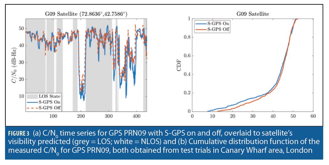
Some of the performance benefits of S-GPS/GNSS may be illustrated using GPS data collected from a vehicle test in London during 2016. Figure 3(a) shows the measured C/N0 of one of the GPS satellites with S-GPS on and off. Satellite visibility predictions obtained using 3D mapping and the truth reference are also shown. It can be seen that the C/N0 during NLOS reception is lower when S-GPS processing is on, demonstrating that S-GNSS can attenuate reflected signals. Figure 3(b) then presents the Cumulative distribution function (CDF) of the same C/N0 data, showing a slight shift towards lower C/N0 values when GPS is on.
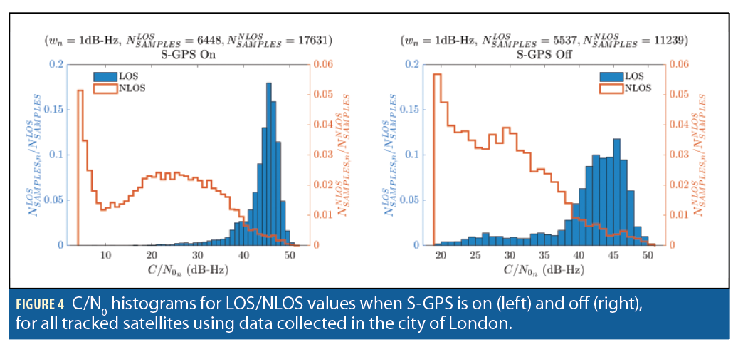
Figure 4 shows the carrier-power-to-noise-density ratio, C/N0, measurement distributions for LOS and NLOS signals from all of the GPS satellites with and without supercorrelation. Again, the truth reference and 3D mapping were used to determine which signals were NLOS and which were direct LOS. With supercorrelation on, there is less overlap between the LOS and NLOS distributions. This makes it easier to infer from the C/N0 measurements whether a signal is LOS or NLOS. Thus, GNSS shadow matching can be expected to perform better with supercorrelated measurements than with the corresponding conventional measurements. The same applies to conventional GNSS positioning algorithms that use C/N0 to weight the measurements.
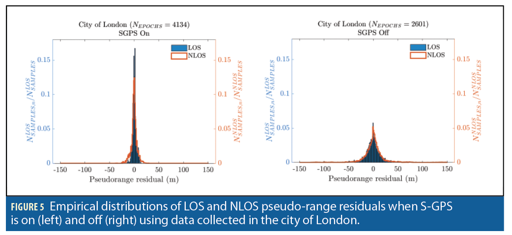
Figure 5 shows the pseudo-range residuals of a conventional least-squares positioning algorithm using LOS and NLOS signals from the GPS satellites with and without supercorrelation. The standard deviation for both the LOS and NLOS signals is much smaller using the superorrelated measurements than the conventional measurements. Thus, any ranging-based GNSS positioning algorithm, whether aided by 3D mapping or not, can be expected to perform better with supercorrelated measurements than with the corresponding conventional measurements.
3D Mapping-Aided GNSS
3DMA GNSS technique improves performance in dense urban areas by using maps of the buildings to predict which signals are directly visible at any given location. Many different approaches have been demonstrated, but each may be broadly classified as either ranging or shadow matching. The simplest 3DMA ranging algorithms use predicted satellite visibility from 3D mapping to discard or downweight those signals predicted to be NLOS at a known location. More sophisticated approaches use LOS/NLOS predictions over a range of candidate positions, reflecting the uncertainty of initialization from conventional GNSS positioning in a dense urban environment. Some researchers use the 3D mapping to correct those signals predicted to be non-line-of-sight (NLOS). This should enable higher accuracy, but computing NLOS corrections using 3D mapping is more computationally intensive than just predicting satellite visibility, limiting the number of candidate positions that can be considered if corrections are to be computed in real-time. Precomputing NLOS corrections over a grid of candidate positions, satellite azimuths and elevations has been proposed, but this would require around 10GB of data per km2. Alternatively, the processing load can be reduced by using predicted pseudoranges based on the satellite elevation angle and distance to the reflecting surface. 3DMA ranging algorithms have also been applied to the components of multipath-contaminated signals, separated using Doppler-domain signal processing when the receiver is moving.
Shadow matching determines position by comparing the measured signal availability, carrier-power-to-noise-density ratio, C/N0, or signal to noise ratio (SNR) measurements with satellite visibility predictions from 3D mapping over a grid of candidate positions. Shadow matching tends to be more accurate in the across-street direction due to the building geometry. Conversely, ranging tends to be more accurate in the along-street direction because there are more direct LOS signals in this direction. Thus, in general, best performance is obtained by using both 3DMA ranging and shadow matching.
As well as the algorithm design, 3DMA GNSS performance is also affected by the receiver design, the environment, and the 3D mapping quality. For both 3DMA GNSS and conventional GNSS, geodetic receivers give better performance than consumer-grade receivers, which in turn give better performance than smartphones, mainly due to the polarization discrimination of the antenna. Environmental factors that impact performance include sky visibility, building height and street width, building materials and passing vehicles. All positioning methods exhibit poorer accuracy in environments dominated by glass and steel buildings, as these buildings produce stronger reflected GNSS signals, increasing multipath errors and making it more difficult to distinguish LOS and NLOS signals using C/N0. In terms of 3D mapping quality, using full 3D city models (level of detail 2) can be expected to give better performance than simple block models that do not account for variations in building cross section with height (level of detail 1). Out-of-date mapping is also a problem.
Many applications that benefit from 3DMA GNSS can run on a smartphone. A smartphone platform also provides a convenient means of downloading building boundary or 3D mapping data from a server, a potential augmentation to assisted GNSS. The Android application program interface (API) now provides “raw GNSS measurements” in the form of pseudorange and C/N0 measurements from compatible GNSS chipsets, enabling advanced GNSS positioning algorithms to be hosted on the device’s CPU. Thus, 3DMA GNSS algorithms can be implemented in real-time on an Android smartphone, as has already been demonstrated for shadow matching. Alternatively, the GNSS measurements may be uploaded to a server for remote computation of the position solution.
UCL’s 3DMA GNSS Positioning Algorithms
At UCL, the focus has been on 3DMA GNSS algorithms that can potentially operate in real time over a wide search area, handling a large initialization uncertainty. Therefore, satellite visibility is predicted using pre-computed building boundaries for a grid of candidate positions. These describe the minimum elevation above which satellite signals can be received at a series of azimuths and are precomputed for each candidate position. A signal can then be classified as LOS or NLOS simply by comparing the satellite elevation with that of the building boundary at the corresponding azimuth. Note that data storage requirements for precomputed building boundaries are about 100 times less than for precomputed NLOS corrections.
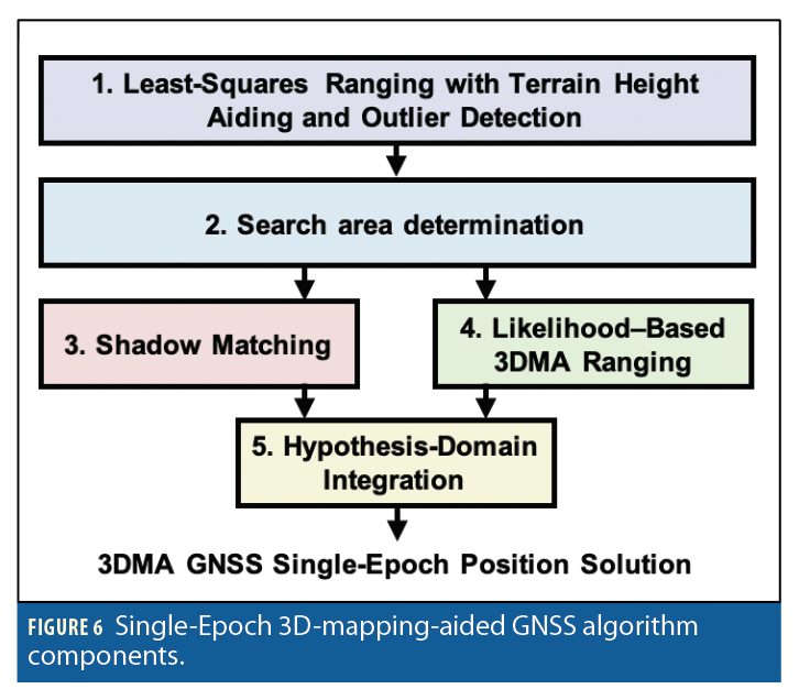
UCL’s implementation of 3DMA GNSS comprises five stages, as shown in Figure 6. A terrain-height-aided least-squares ranging (LSR) algorithm with outlier detection is used for initialization. The residuals are then used to determine the size of the search area for the subsequent stages. Next, a likelihood-based ranging (LBR) algorithm scores candidate position hypotheses according to the correspondence between measured and predicted pseudoranges. Different error distributions are assumed at each candidate position according to which signals are predicted to be NLOS at that location. A shadow matching (SM) solution is computed and then integrated with the LBR solution in the hypothesis domain before extracting a position solution from the combined likelihood surface. Currently, only single-epoch 3DMA positioning has been implemented.
The least-squares ranging algorithm weights the pseudo-range measurements according to the corresponding C/N0 measurements. Inter-constellation timing bias corrections from the navigation data messages are applied. Outliers are removed with a sequential elimination loop. If the detection threshold is exceeded, the measurement with the largest residual is eliminated and the solution re-calculated. This continues until either the threshold is met or only four measurements remain.
Once an initial position solution has been obtained using pseudo-ranges only, the terrain height at the corresponding position is obtained from a digital terrain model (DTM), also known as a digital elevation model (DEM). This is used to generate an additional virtual range measurement, comprising the distance from the center of the Earth to the user antenna. The LSR algorithm then computes a terrain-height-aided position solution using the pseudo-range and virtual range measurements. An incorrect horizontal position solution leads to an incorrect terrain height, so the terrain height determination and LSR positioning algorithms are iterated up to 20 times to minimize these errors.
The next step is to determine the search area for 3DMA GNSS as both the likelihood-based ranging and shadow matching algorithms score candidate positions according to the correspondence between measurements and predictions. If the search area is too small, it will not include the true position, making a correct solution impossible. Conversely, if the search area is too large, there may be multiple locations where there is a good match between measurements and predictions. Such ambiguous solutions can be a common feature of shadow matching in particular due to repeating building geometry. Therefore, the search radius is scaled according to the quality of the LSR solution, which is estimated from the residuals. Once the search area has been determined, a regular grid of candidate positions is set up with spacing proportional to the search area to maintain a constant processing load. The DTM is used to associate a terrain height with each horizontal position, removing the need for a three-dimensional search space. Terrain-height aiding is thus implicit in 3DMA GNSS.

SHADOW MATCHING COMPRISES THE FOLLOWING STEPS:
• For each candidate position in the search area, the satellite visibility is predicted using the building boundaries precomputed from the 3D city model.
• The probability that each received signal is direct LOS is determined from the C/N0 measurements using an appropriate statistical model.
• Each candidate position and satellite is scored according to the match between the predicted and measured satellite visibility; visibility predictions are not assumed to be perfect
• An overall likelihood score is computed for each position by multiplying the scores for each satellite.
THE LIKELIHOOD-BASED 3DMA RANGING ALGORITHM, COMPRISING THE FOLLOWING STEPS:
• For each candidate position, the satellite visibility is predicted using the building boundaries.
• At each candidate position, one of the satellites predicted to be direct LOS is selected as the reference.
• At each candidate position, the direct LOS range to each satellite is computed and then measurement innovations are calculated by subtracting the computed ranges from the measured pseudo-ranges and then differencing with respect to the reference satellite. This eliminates the receiver clock offset.
• At each candidate position, the measurement innovation for each satellite predicted to be NLOS is re-mapped by using a skew normal distribution to determine the cumulative probability and then substituting the corresponding direct LOS innovation with the same cumulative probability. This enables the NLOS measurements to be scored using an asymmetric distribution which accounts for the error due to NLOS reception always being positive, but treated like Gaussian-distributed measurements in the next step.
• A joint likelihood score for each candidate position is computed using the measurement innovations and their error covariance matrix, noting that all innovations are correlated with each other due to the common reference satellite.
Finally, the likelihood-based ranging and shadow matching solutions are combined. This exploits the fact that shadow matching tends to be more accurate in the cross-street direction in dense urban areas, while ranging based position solutions tend to be more accurate in the along-street direction. Hypothesis-domain integration is used, which combines the shadow-matching and 3DMA ranging scores to give a single score for each candidate position. This down-weights any parts of the search area that are given a high score by shadow matching and a low score by likelihood-based ranging, or vice versa. Finally, the position solution is obtained by using the combined scores to weight the candidate positions.
Experimental Test
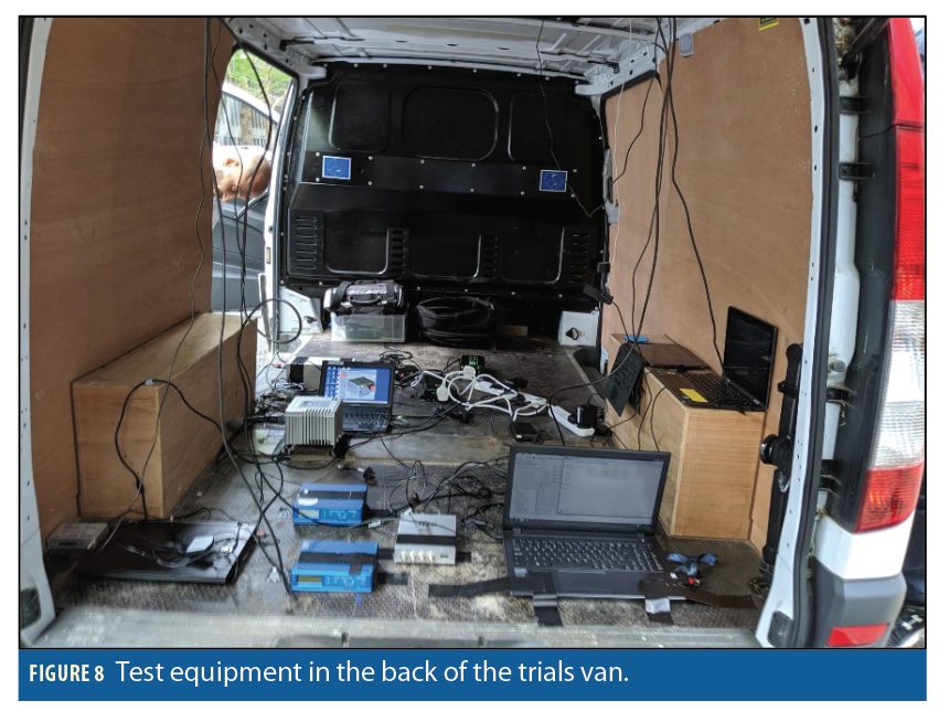
GNSS signals were recorded using a Racelogic Labsat 3 GNSS front end on a trials van in the Canary Wharf area of London and subsequently processed to generate conventional and supercorrelated ranging and signal-to-noise measurements from the GPS and Galileo satellites. A truth reference was obtained from a Novatel iMAR INS/GNSS system. Figure 7 shows the van trajectory from the truth reference data and Figure 8 shows the equipment. The van travelled clockwise on the route and the northmost section was traversed twice. The central area, highlighted in red, contains many tall buildings (the highest is 235m) clad in metalized glass and steel, which presents a very challenging reception environment for GNSS. The rest of the route is much lower. Separate positioning performance statistics are provided for the central area and the other areas.
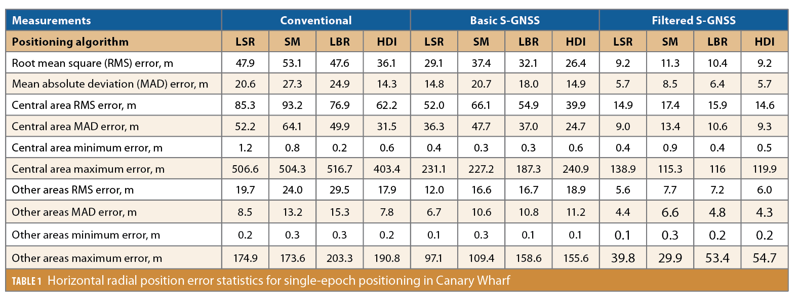
Four position solutions were computed with both the conventional and S-GNSS measurements. These are a conventional least-squares ranging (LSR) solution with terrain-height aiding and outlier detection, and three 3DMA GNSS solutions: shadow matching (SM), likelihood-based ranging (LBR) and hypothesis domain integration (HDI) of the SM and LBR solutions. Terrain-height aiding is implicit in 3DMA GNSS. Two different types of S-GNSS pseudo-range measurements were used, simple code-based pseudo-ranges and filtered carrier-smoothed pseudo-ranges with outlier detection applied to reject the code component where it is inconsistent with the carrier-based component. This can correct NLOS reception errors in cases where the reflected signal has the same Doppler shift as the direct, such as where the reflecting surface is parallel to the direction of travel. Carrier-smoothing also significantly reduces multipath errors when the multipath environment is rapidly changing. The basic S-GNSS measurements are representative of a one-time position fix while the filtered measurements are representative of continuous positioning.
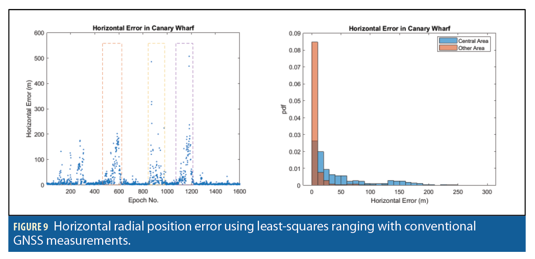
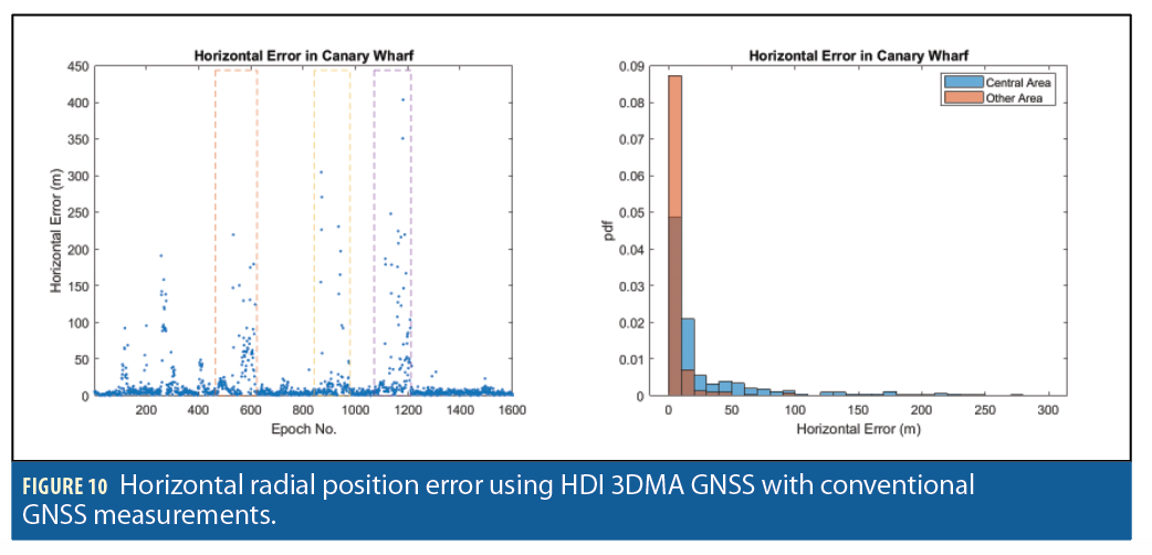
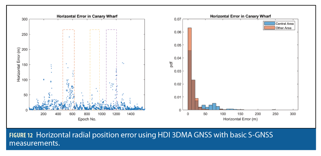
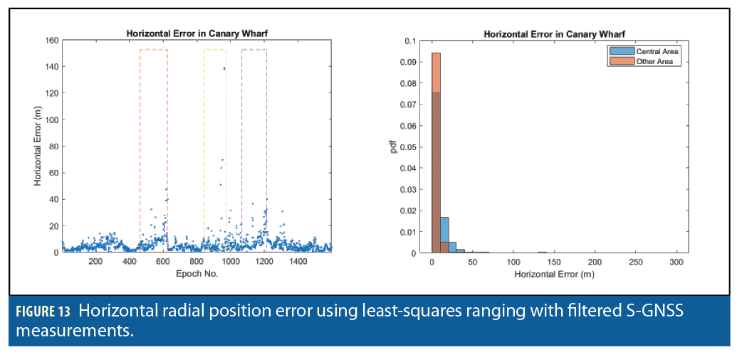
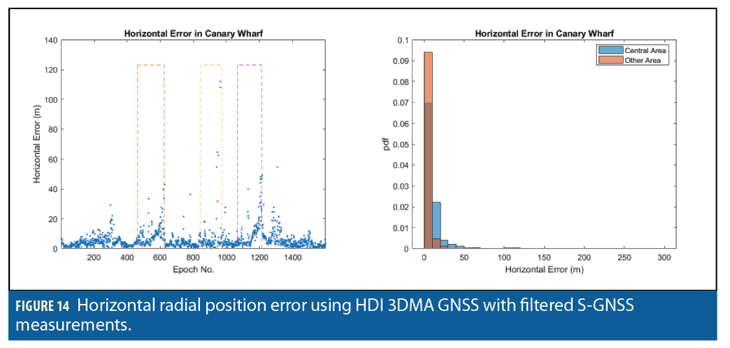
Table 1 presents horizontal radial position error statistics for all 12 solutions. Figures 9, 10, 11, 12, 13 and 14 show the position error as a function of time and the position error distribution for the Central and other areas for, respectively, the LSR solution using conventional measurements, the HDI solution using conventional measurements, the LSR solution using S-GNSS measurements, the HDI solution using S-GNSS measurements, the LSR solution using filtered S-GNSS measurements and the HDI solution using filtered S-GNSS measurements.
The results show a large improvement from using supercorrelation. With conventional least-squares positioning, using S-GNSS reduces the root mean square (RMS) position error by 39%, both in the central high-density area and elsewhere. The smaller impact in the central area is likely due to the limited number of direct LOS signals as supercorrelation has more impact on multipath interference than NLOS reception. Using the filtered pseudo-range measurements reduces the RMS position error by a further factor of 3.5 in the central high-density area and a factor of 2.1 elsewhere.
Comparing the 3DMA GNSS solutions with the LSR solutions, it can be seen that a shadow-matching-only solution does not improve the position accuracy. This is to be expected as shadow matching was always intended to be used alongside ranging-based positioning, primarily to improve accuracy in the cross-street direction. With conventional GNSS measurements, the RMS position error of the LBR solution generally performs slightly better than the LSR solution in the central area, but performs worse in the other areas. However, the HDI solution performs consistently better than LSR, with a 27% reduction in RMS position error in the central area and a 9% reduction elsewhere. This demonstrates the synergy of shadow-matching with ranging. With basic S-GNSS, the benefits of 3DMA GNSS are smaller with the LBR solution consistently worse than the LSR solution and the HDI solution reducing the RMS position error by 23% , compared with LSR, in the central area, but increasing it elsewhere.
Using the filtered S-GNSS pseudo-ranges, the LBR solution performs consistently worse than the LSR solution, while the HDI solution is of a similar accuracy to the LSR solution. Because the filtering of the measurements already reduces the impact of NLOS reception, there is much less scope for 3DMA GNSS techniques to improve position accuracy.
At individual locations, 3DMA GNSS improves positioning accuracy in some cases and not others. Further investigation of selected individual results is needed to understand why this is. Different reasons are likely to apply in different places. Mapping errors will sometimes lead to 3DMA GNSS positioning errors as will large passing vehicles that block and reflect GNSS signals. The LSR algorithm currently includes outlier detection while the 3DMA GNSS algorithms do not; adding this should help to reduce the impact of vehicles and mapping errors. Also, Lastly, in open areas where conventional GNSS positioning works well, 3DMA GNSS can’t be expected to improve on it.

Conclusions
The single-epoch positioning results have clearly demonstrated the benefit of supercorrelation with position errors using S-GNSS measurements. Using conventional positioning techniques, using supercorrelation on its own reduces position errors by 40% using conventional positioning techniques. However, combining supercorrelation and filtered carrier-smoothed pseudo-ranges using outlier detection to reject code components that are inconsistent with the carrier-based component reduces the position errors by a factor of 5.7 in the densest of environments and a factor of 3.5 elsewhere.
For single-epoch positioning, using pseudo-ranges from code tracking only with both conventional and supercorrelation, 3DMA GNSS improves the position accuracy by about 25% in the denser environments, but does not bring any benefits in the more open areas. However when filtering with outlier detection is used to produce carrier-smoothed pseudo-ranges, 3DMA GNSS techniques have little impact on the positioning accuracy with S-GNSS processing because the impact of NLOS reception has already been reduced. Thus, 3DMA GNSS techniques are likely to be more useful for snapshot positioning techniques and potentially for the initialization of filtered solutions than for continuous positioning.
Future Work
There is clearly a need for substantial improvement in the 3DMA GNSS algorithms before this approach can be recommended for use. Areas to investigate include
• Improved scoring models for LBR and SM that take into account additional factors, such as satellite elevation, street width, building height and relative azimuth of the satellite and street direction.
• Optimizing the satellite visibility prediction.
• Finding the best way of combining the LBR and SM likelihood distributions to get an optimal overall positioning solution.
• Outlier detection.
• Improved search area determination, potentially considering non-circular search areas.
• The impact of higher-resolution 3D mapping.
• Multi-epoch 3DMA positioning using Bayesian filtering techniques.
In addition, using S-GNSS Skyscan data to estimate the signal strength, Doppler shift, and pseudo-ranges for all of the different paths the signal takes between the satellite and receiver antennas for each epoch, increases the information per measurement epoch that can be combined with knowledge of the 3D building model.
Acknowledgments
Qiming Zhong is funded by the China Scholarship Council and a UCL Engineering Faculty Scholarship. The authors thank UCL Ph.D. student Eleftherios Plakidis for producing figures 3, 4 and 5 and for assisting with the data collection. The authors also thank Imperial College London for use of their trials van and reference system, and Canary Wharf Group plc, particularly Ms Lesley Johnson, Canary Wharf Central Records Manager, for their permission to collect GNSS data in the Canary Wharf Estate. This article is drawn from a paper presented at ION GNSS+ 2020. For full version, see www.ion.org/publications/browse.cfm.
Authors

Paul Groves is an associate professor at University College London (UCL), author of Principles of GNSS, Inertial and Multi-Sensor Integrated Navigation Systems, recipient of ION’s 2016 Thurlow Award and a Fellow of the Royal Institute of Navigation. He holds a doctorate in physics from the University of Oxford.

Qiming Zhong is a Ph.D. student at UCL, specializing in 3D-mapping-aided GNSS. He holds an MSc in Robotics and Computing from UCL.

Ramsey Faragher is founder and CEO of Focal Point Positioning. He is the recipient of ION’s 2019 Per Enge Award and a Fellow of the Royal Institute of Navigation. He holds a doctorate in physics from the University of Cambridge.

Paulo Esteves is a principal scientist at Focal Point Positioning. He received his Ph.D. in aerospace engineering from the University of Toulouse.


