A wheel-mounted inertial measurement unit provides high-rate (2 kHz) bias-free data for vehicle navigation, road-quality measurement systems and instantaneous wheel dynamics estimation for vehicle stability control.
Microelectromechanical systems (MEMS) play an essential role in automotive electronic control systems, providing measurements for tire pressure monitoring, vehicle stability control, adaptive suspension, rollover protection systems, and navigation systems. While MEMS gyros and accelerometers are suitable for vehicular applications in terms of size and cost, noise properties (large bias and significant 1/f noise) create problems, especially in low dynamic conditions or when measurements are integrated from angular rates to angles or from acceleration to velocity and position. GNSS receivers can complement these measurements but the availability and accuracy drops in urban canyons and underground.
Mitigation of MEMS gyro noise is an actively studied topic, and solutions vary from improving the associated electronics to using external updates and advanced statistical signal processing methods for filtering the gyro noise while retaining the signal. However, in the absence of external updates it is impossible to transform a low-cost MEMS gyro to a high-performance low-noise gyro with signal processing methods alone. This is due to the fact that the 1/f noise heavily overlaps with the useful signal frequency bands, especially when the vehicle dynamics are low.
To isolate the problematic noise components from the signal, methods such as indexing and carouseling have been studied. Significant improvements in pedestrian dead reckoning obtained using a foot-mounted rotating inertial measurement unit (IMU) involved complicated hardware. In contrast, a dedicated rotating system is not necessary if the IMU is mounted at the wheel of a land vehicle. This setup is advantageous as distance traveled can also be deduced from wheel orientation via known radius. Somewhat similar approach is taken in foot-mounted INS wherein zero-velocity update can be applied as measurement whenever foot is on ground. On a wheel, this kind of velocity update can be done continuously.
We have designed a wheel-mountable sensor system that contains MEMS sensors, battery, Bluetooth module and electronics to run computations and navigation algorithms onboard. It operates in several programmable modes:
• Computes navigation parameters real-time and sends them via Bluetooth to an onboard computer (can be any other integrated system, data logger or a tablet)
• Sends real-time raw data to an onboard computer
• Records hi-rate raw sensor data (up to 2 kHz) to an embedded micro-SD card.
Our onboard computer is a MEMS-array IMU with 48 gyro and accelerometer channels (PI-48), with a Bluetooth receiving and sync controller, data storage and WiFi interface. We can connect units from all wheels to the onboard computer and have all their data in sync with the in-cabin PI-48 inertial data. All of this data can be used for navigation, wheel dynamics measurements or road quality monitoring applications.
The output of the system can be useful in several ways:
• for positioning;
• for wheel dynamic measurements: high-rate (2kHz) 6DOF data;
• for road condition monitoring: direct measurements unaffected by suspension.
An inertial measurement unit attached to a wheel is evidently in a harsh environment. When compared to a cabin-fixed IMU, conditions like vibration, dirt, moisture, snow, varying temperature due to braking all need to be taken into account. In addition, requirements for sensor input range are different. But such environmental factors are not that severe when compared to space applications, for instance. Thus, designing and building IP-protected, properly temperature compensated unit (-40°C to +80°C) is not impossible.
For guiding the system design, our primarily targeted markets and applications for this technology have been:
• autonomous vehicles;
• construction and mining machines navigation and safety;
• port logistics and warehouse automation vehicles;
• traction control enhancement and tire wear analysis.
We have ongoing efforts to design and test an energy- harvester prototype capable of extracting enough energy to power the sensor even in slow vehicle speeds. This will make our wheel sensor an “install and forget” solution that goes to sleep when a vehicle is not moving (motion detection) and transmits pre-programmed data messages for an onboard system when motion occurs. Our target design goal is a small unit behind the manufacturers logo on a wheel rim, self-generating enough power to operate, and sending valuable information for in-car safety/navigation systems.
Dynamics of Wheel-Mounted IMU
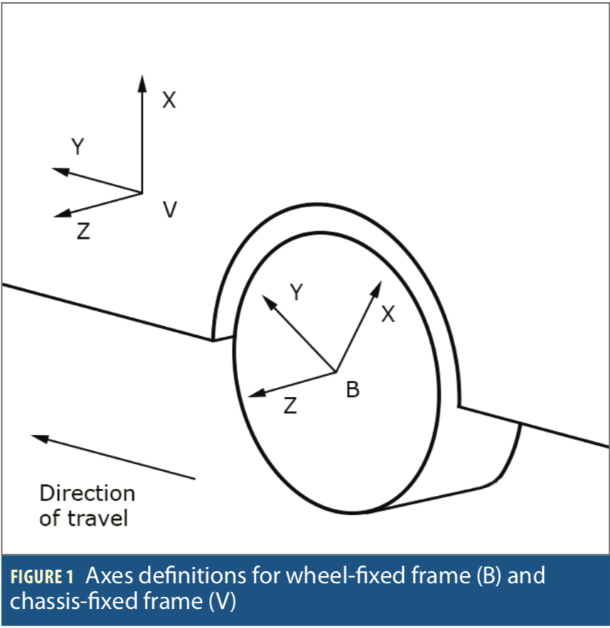
We begin by defining wheel-fixed coordinate frame (B) and vehicle chassis frame (V), sharing a common z-axis as shown in Figure 1. The direction cosine matrix for coordinate transformation can be then expressed as

where φ denotes wheel phase angle, the amount of rotation from neutral angle where the frames V and B coincide. Vehicle heading rate (ωH ) and roll rate (ωR) are observed by wheel- mounted IMU as

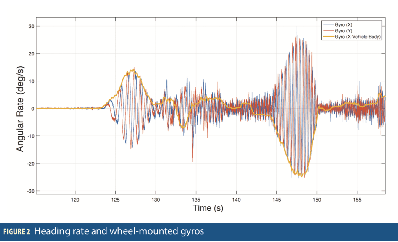
Heading rate from the in-cabin IMU (gyro X) vs. data from two gyros in the unit on the wheel (gx and gy) are shown in Figure 2. As Eq. 2 shows, the turn rate of vehicle is modulated in the wheel angle “carrier.” The direction of turn is not visible in raw data but appears as unbiased heading rate after coordinate transformation.
Assuming the wheel rotates at a constant speed, φ(t) = rt, the constant bias will cancel out and the low-frequency noise significantly decreases. Our tests indicate that the bias cancellation works well even with an accelerating vehicle as acceleration and biases can be observed with an extended Kalman filter framework.
Velocity updates and centripetal acceleration. The required coordinate transformation  should be performed with aid of external angle information that does not suffer from drift; accelerometers are conveniently available for this. The accelerometer triad measures specific force acceleration

where  B is acceleration in body frame. Assuming it is known or a noise term n one obtains

Furthermore, assuming the locally level L frame coincides with the vehicle frame V

and thus the first row of in (1) is observable, and phase angle φ(t) can be estimated. This is just one way to approach the filtering problem in wheel-mounted inertial systems. For example, the wheel contact point can be assumed stationary and zero-velocity observation can be thus added in the filter. In this sense the wheel-mounted inertial system is another example of applying velocity constraints, with the extra aid of carouseling effect. The unbiased-ness can also improve the centripetal acceleration estimation. Assuming Ackermann steering geometry and zero slip angles, the lateral acceleration can be computed, using

And radius of curvature is

If heading rate estimates are averaged over full wheel revolution the gyro bias does not affect the lateral acceleration estimate. The remaining essential errors are due to gyro white noise, inaccuracy in wheel radius R and inaccuracy in φ. In wheel-mounted INS the accelerometer errors can be also tackled efficiently when bias, tilt error, and vibration affect the results much less than in the traditional approaches. Coarse estimate for the acceleration error due to angular random walk noise can be obtained by using the Allan deviation specification of the gyro at _= T, and multiplying it by φR. For low-cost MEMS gyro with noise density 0.023 dps/_Hz and heavy equipment vehicle traveling at 20km/h, the resulting error (1 sigma) would be approximately 0.11 m/s2.
Hardware and Data Format
The sensor board is rigidly attached to the enclosure, limiting negative resonant effects and proving maximum stability for the sensitivity axes stability. The sensor board is also thermally detached from the enclosure to minimize temperature gradients. After the assembly, the sensor is calibrated (axes, biases and scale factors) and temperature compensated from -40°C to +80°C.
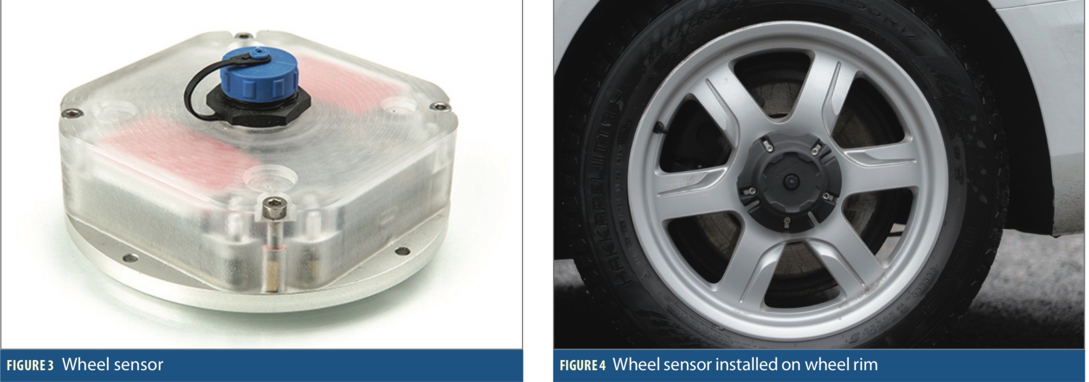
The unit uses ARM Cortex-M4 as the main processor. The radio channel is built on Bluetooth technology using Murata chip and BLE (Bluetooth Low Energy) protocol. The built-in Li-pol battery has a capacity of 240 mAh and is enough for powering the PI-WINS for 10-20 hours, depending on the load of BLE transmission (mode of operation). There is also a built- in eMMC 16gB flash memory card for logging hi-rate sensor data (up to 2 kHz) for specific wheel dynamic measurements. The logged hi-rate data is accessible via a mini-USB interface that is IP-68 protected. The current model of wheel sensor is shown in Figure 3, with an example of its installation on a car rim in Figure 4.
In testing we also used a another IMU that we design and manufacture with an array of 48 gyros and accelerometers. The proper orientation of the sensors in the array not only lowers the noise and improves the bias stability, it also reduces overall temperature coefficient and hysteresis, which, in turn, leads to better units stability after temperature calibration. The unit is IP-67 protected and has several interfaces: RS232, RS485 and CAN2.0. This IMU is shown in Figure 5.

Data Format
The wheel sensor, as any other inertial sensor, provides relative navigation solution: incremental heading (with respect to some initial value) and incremental distance traveled, measured in wheel rotation counts. It is sufficient information to apply a classic Dead Reckoning (DR) algorithm and compute a 2D navigation solution. The initial heading, wheel diameter and altitude can be estimated with GNSS integration or modern map-matching methods [27]. Currently, the wheel sensor operates in 2 modes:
• Low power mode (real time): all the calculations are made in the sensor and the real-time delta-heading and delta-distance are sent via bluetooth to a dedicated receiver;
• EKF mode (time lag): raw sensor data is transmitted to an onboard computer where more computationally heavy EKF algorithms are run and better navigation solution is computed.
For the low power mode, the current accuracy specifications for the unit are:
• Output data packet rate: 10 Hz;
• Interface: USB (with BT dongle);
• Wheel rotation rate: up to 10 full revolutions per second (600 rpm);
• Wheel heading angle rate: <1000 deg/sec;
• Wheel heading angle error: 1 deg per 1 hour of driving time.
Test Results
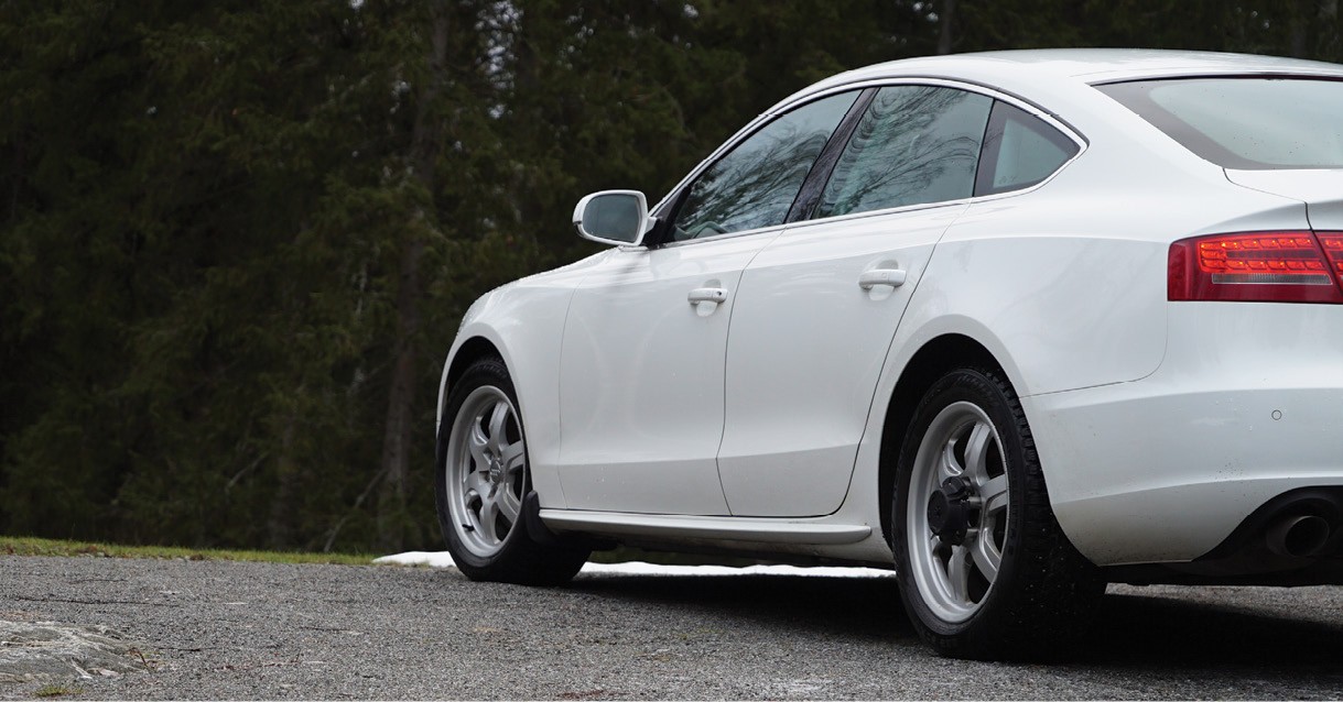
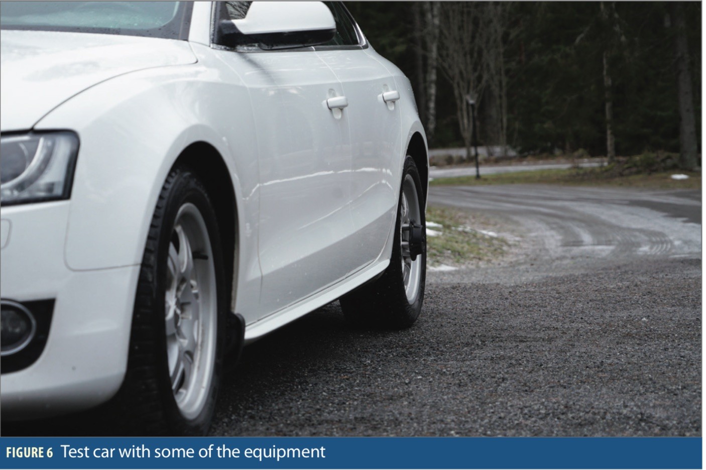
Test vehicle with the wheel sensor and the BT dongle on the wheel is shown in Figure 6.
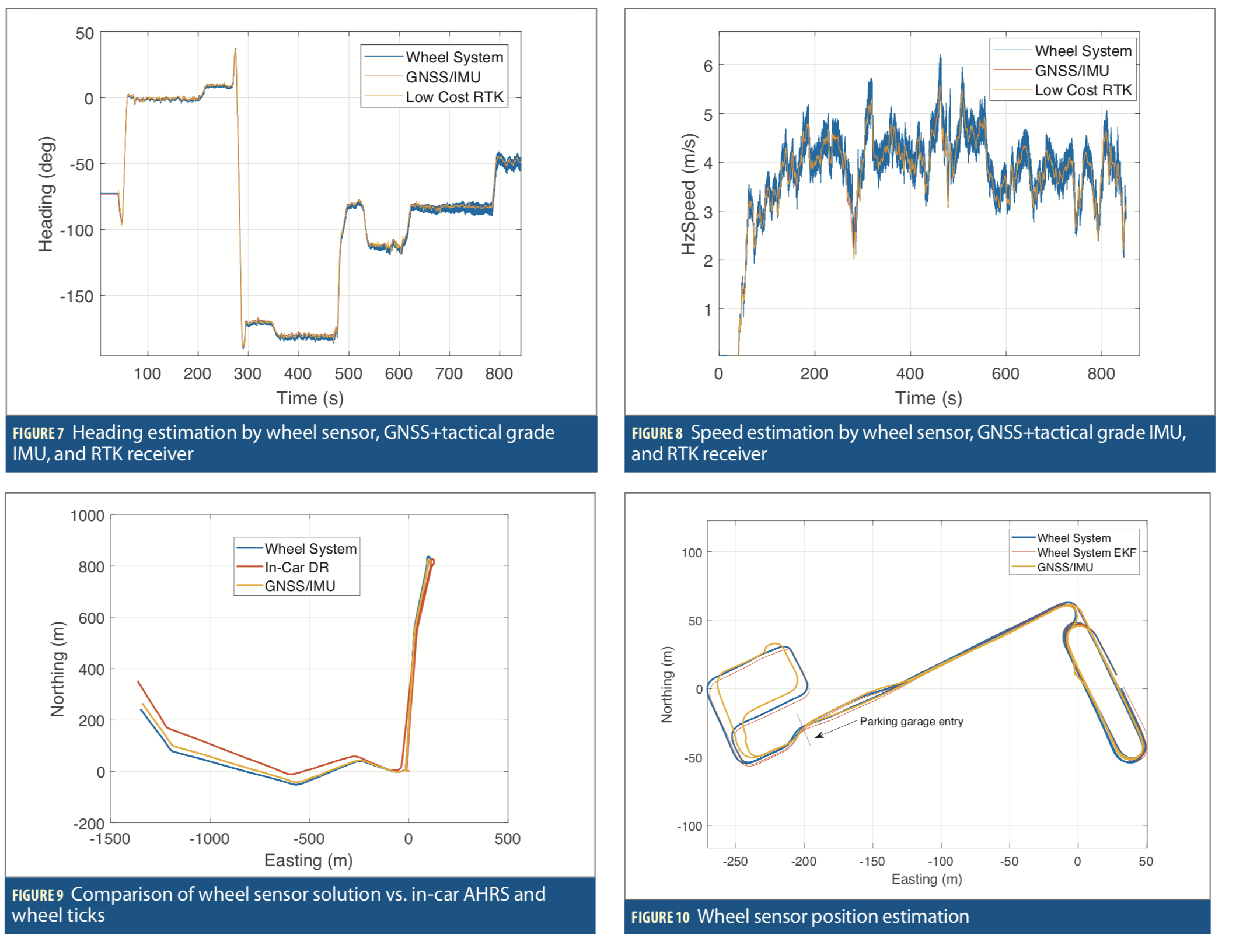
The most important data from the wheel sensor is the unbiased heading and precise wheel rotation count. Let us first demonstrate how well it estimates the vehicle heading compared to two other solutions: one incorporating a high-precision GNSS receiver and a tactical grade IMU, the second a multi-band RTK GNSS receiver. Figure 7 shows the result of a nearly 15 min drive with speeds of up to 25 km/h. After initial heading initialization, the max error in heading estimation is around 2.3 deg (RMS).
Figure 8 shows the estimation of vehicle speed by the three devices. Here, we used wheel sensor measurements of wheel rotation and the known wheel diameter. The error in speed estimation is 0.23 m/s (RMS).
Figure 9 shows the results for this test: 15 min drive, 3.1 km total distance traveled, 20 km/h max speed. For the wheel sensor computation the final 2D position error is 23 meters. In comparison, high-accuracy MEMS-array IMU with odometer input has larger error (112 m). It should be noted that for the latter result the initial bias was removed in the initialization. This also removes the vertical component of Earth rate. For the wheel sensor, the Earth rate remains in the solution (this is not corrected in the results). We expect the difference to be even larger with filter that is tuned to hanbdle errors distinctive to wheel-mounted INS (modulation of Earth rate and g-sensitvity). In here the progress in low-cost precise GNSS receivers should be mentioned, as it is very relevant to inertial system integration. We have tested the new GNSS RTK module with the wheel sensor and results look very promising. For example, the real-time solution of this low-cost receiver was used to estimate the lever arm with standard deviation of only 1.4 cm. Such advances in new low-cost receivers will really change the opportunities of dead reckoning systems in general.
In another shown test, the total driving time is 15 minutes and max speed is 30 km/h. Figure 10 shows the results for this test; initial heading and position are taken from DGPS solution, the rest is fully inertial 2D navigation solution computed from the sensor’s wheel data. Here, we show 2 modes of wheel sensor operation—one is a real time computation by the wheel sensor itself (low power mode, wheel sensor transmits via Bluetooth delta-heading and delta-distance traveled at 10Hz) and the other is a more computationally heavy algorithm (EKF) that is run on a computer using raw 2kHz data logged by the sensor on its internal storage. The two solutions are really close in this particular case, but in the longer tests EKF solution outperforms the simplified real-time solution. It is possible to embed the EKF algorithm to the ARM processor of the sensor; it will result in a more accurate solution but will also lead to a shorter battery operation time and inevitable solution time lag.
When the car enters a parking garage (“parking garage entry” mark on Figure 10) the reference GNSS/INS solution actually drifts more than the sensor’s solution. The maximum 2D position error of the sensor is below 10 meters. This test shows the potential of the system, and we are running an extensive test campaign with other types of additional sensors such as Lidars, stereo cameras and precise point positioning receivers. This campaign will help to reveal the pros and cons of wheel-mounted systems with different kinds of sensor setups.
Many other applications and tests can run with wheel sensors. For example, having several sensors on front and rear wheels can be very useful in detecting wheel slips. Data from four sensors installed on all vehicle wheels can be used to estimate the radius and center of curvature of the path the car drives at. The sensor’s raw 2kHz inertial data is perfect information to analyze wheel dynamics and road conditions. Here we have just scratched the surface and shown rather navigation-related results.
Conclusions
Availability, reliability and integrity of vehicular navigation technology become more and more critical as autonomous transport systems enter the market with high volume. To enable continuous operation, cameras and LiDARs equipped with modern machine learning algorithms are being coupled with traditional GNSS and inertial navigation systems. When considering system tolerance to interference (intentional or unintentional) inertial sensor-based solutions are in their own class. Thus, improving performance of inertial systems while keeping the costs at reasonable level is worth studying. We have shown that inertial measurement unit mounted to the wheel of a vehicle can be used as a high-rate (2 kHz) source of bias-free data for
• vehicle navigation
• instantanious wheel dynamics estimation (angles, rates, accelerations) for vehicle stability control
• road quality measurement systems.
This method opens potentially new methods for car stability systems and autonomous driving.
Manufacturers
The Wheel Measurement Systems (PI-WMS) and PI-48 IMUs are produced by Pacific Inertial Systems of Canada and JC Inertial Oy of Finland. They carry Invensense ICM-20602 inertial motion tracking devices.
Authors
Oleg Mezentsev is founder and CEO of Pacific Inertial Systems Inc. and holds a Ph.D. degree from University of Calgary. His research focus includes on-wheel inertial navigation, MEMS-array IMUs, and inertial integration for AR/VR applications.
Jussi Collin is CEO of Nordic Inertial (JC Inertial Oy) and adjunct professor at Tampere University. His research interests are in modern machine learning methods and their industrial applications in the field of inertial sensing.


