This major shift in architectural framework would spatialize core SBAS components within a distributed network of LEO satellites.
SÉBASTIEN TRILLES, THIERRY AUTHIÉ, XAVIER VASSEUR, MARIE ABBAL, THALES ALENIA SPACE, TOULOUSE, FRANCE
To use GNSS systems for air navigation, various civil aviation organizations have defined an augmentation system capable of fulfilling two primary missions. The first is to calculate correction messages that allow aviation users to exploit GNSS data for precise positioning, even if the GNSS system incorporates intentional or unintentional degradations affecting geolocation. The second mission is to monitor all navigation data broadcast by GNSS systems in real time to detect any anomalies and alert aviation users within a timeframe compatible with their flight phase. Given civil aviation’s need to cover a large area, typically on the scale of a continent, the dissemination of these messages has naturally been directed toward geostationary satellites known as Satellite Based Augmentation Systems (SBAS).
The role of an SBAS is to decompose the various contributors to measurement errors and broadcast, through dedicated augmentation messages, corrections associated with each error contributor to users. These corrections are reassembled by the user receiver according to their geographical position, improving positioning accuracy and helping to mitigate error sources that affect distance information related to satellite clocks, their positioning, and ionospheric effects. All SBAS are interoperable and standardized [1].
The classic functional architecture of an SBAS is composed of a network of ground reference stations that collect GNSS navigation measurements and data, a set of central processing facilities that compute corrections and constructs augmentation messages, and a set of transmission stations that broadcast the radiofrequency signal toward the geostationary satellite.
Current SBAS systems are designed for single constellation GPS, single-frequency L1 users, using the L/NAV navigation message. The augmentation signal is broadcast on the L1 frequency band, modulated by a dedicated PRN, and contains orbital corrections, clock corrections, and a model to correct ionospheric elongation.
Future SBAS, called Dual Frequency Multiple Constellations (DFMC), are dedicated to dual-frequency L1/E1 and L5/E5a users, using L/NAV navigation messages for GPS and F/NAV for Galileo. The augmentation signal is broadcast on the L5 frequency band, modulated by a dedicated PRN, and contains orbital and clock corrections for satellites from different constellations.
The main limitation of SBAS accuracy and availability performance lies in the regional coverage of the ground reference stations network, which does not allow continuous monitoring of the satellites in the navigation constellation. As a result, SBAS must continuously manage satellite visibility losses for several hours, requiring complex strategies to detect any satellite event such as manoeuvres, clock anomalies and hardware bias as soon as measurements become available again. The strong coupling that exists between material biases and ionospheric elongation adds difficulty in the case of satellite raising because it is often difficult to separate a hardware bias jump and an ionospheric event at the edge of the zone.
Furthermore, a geographically restricted network of reference stations does not allow for the correct decoupling of satellite orbits and clocks. This limitation is not a problem for a small service area because the clock error partially compensates for the orbit error. However, clock error is a scalar while orbit error is a three-dimensional vector, so how good the compensation of one error by the other depends on the size of the geographical area to be covered and the geographical position of the user within it. Consequently, a wide service area needs good decoupling between orbit and clock, which a network of regional stations does not provide.
This article studies the possibility of spatializing all the components of a classic SBAS. In this approach, the three main steps of SBAS processing, collecting GNSS data, calculating augmentation messages and disseminating those messages to users, must be carried out by components in free fall around the Earth.
Global SBAS Architecture Overview
The first step in the SBAS spatialization process involves taking fixed reference stations on Earth and placing them in orbit, under navigation constellations, i.e., in low Earth orbit (LEO). There is no point in flying the stations in cluster formation, as this would not solve the regional problem and, moreover, the service would only be intermittent during the cluster’s orbital period. We immediately assume a uniformly distributed constellation as the geometry for the station distribution.
By doing this, LEO flying stations (LFS) can see GNSS constellations permanently, which is an undeniable advantage for increasing the accuracy of corrections and detecting critical events. Another benefit is SBAS has the capacity to be a global service, representing a significant paradigm shift. The spatialization of the stations also avoids the difficulties of defining a terrestrial network, which must satisfy geopolitical conditions, not to mention that the Earth is 70% covered by oceans, limiting the possible terrestrial sites to emerged geographical areas.
On the other hand, GNSS reference stations are no longer fixed points on Earth; they evolve over time. However, their trajectories remain predictable as their movements are well known and correctly modeled in the short term because they are governed by the laws of space mechanics. It is necessary to have accurate orbits for LFS. Several solutions exist for performing this calculation. Three approaches naturally emerge:
1. The calculation of LFS orbits is performed simultaneously and in the same process as the MEO orbits of the constellation satellites;
2. LFS orbits are estimated using GNSS measurements through a separate process;
3. LFS orbits are calculated using independent means and independent measurements.
The first approach raises several questions regarding the commonality: LFS are devoted to monitor the GNSS constellation satellite. Using GNSS measurements for both LEO and MEO positioning in the same process brings significant
algorithmic complexity and risk on the impact of a feared MEO satellite event on LEO position and detection capabilities. Thus, this approach is not discussed.
The second approach decouples orbit calculations but requires implementing GNSS fault detection and exclusion techniques such as RAIM or ARAIM to make the position of the reference stations insensitive to failures of the constellation satellites.
The last approach offers the greatest possible independence because it is achieved using measurements from a positioning technique that is completely decoupled from GNSS. The Doppler Orbitography and Radiopositioning Integrated by Satellite (DORIS) system is an example of such an independent system. DORIS is a radio navigation and orbit determination system based on Doppler measurements of signals transmitted from the ground to satellites. It is developed and maintained by CNES, the French Space Agency, widely used for space geodesy, Earth observation, altimetry missions and achieving centimeter precision level. The onboard DORIS and GNSS receivers share the same clock. The clock is synchronized with System Network Time (SNT, the reference time of the globalized SBAS), so the orbit generated will be time tagged with respect to the SNT. We retain this for this framework.
At the planned altitude, the LFS are positioned above the area where the ionospheric plasma is most concentrated. The GNSS measurements collected on board shouldn’t be much affected by ionospheric delays. This also implies this type of system will not be able to develop an ionosphere model and calculate ionospheric corrections to single-frequency users. Thus, this framework is devoted for dual-frequencies users. According to this paradigm, the ionosphere model shall be elaborated by an external entity.
The local Earth environment or propagation effects (troposphere and ionosphere) no longer affect measurements collected by GNSS receivers. Therefore, the quality of the measurements is expected to be significantly improved compared to a ground-based system. This favorable environment, associated with a geodetic quality receiver, will improve the precision performance of augmentation navigation messages.
In this framework, the LFS move at a high speed, of the order of 7 km/s, which generates visibility durations for GNSS satellites of 30 minutes. These passage durations are much shorter than those observed from the ground by several hours, but they are long enough for floating ambiguity resolution. The rapid dynamic of the LFS generates high relative movement between LEO and MEO satellites, providing better decorrelation between orbits and clocks and improving SBAS augmentation message performance.
LFS Communicate Via Inter Satellite Links
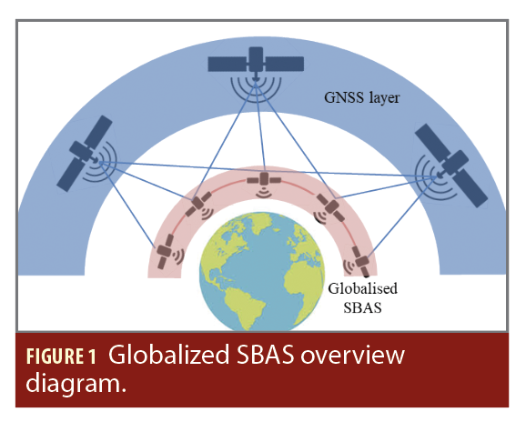
The proposed architectural framework incorporates inter satellite links (ISL) between the LFS (Figure 1). Selecting optical or RF ISL is driven by the trade-off between ranging accuracy, security and volume of data to be transmitted versus satellite design complexity. Optical links are suitable for high bandwidth and security requirements but demand more advanced technology and precise alignment that affect satellite design. RF links represent a proven technology, simple to deploy and tolerant of inaccuracies, but limited in bandwidth and inherent security.
ISL capability serves two functions:
• A communication function to share the information recorded by each satellite;
• A ranging measurement function to improve the algorithms for determining the orbits of LFS and to participate to generate the independent SNT.
The first is equivalent to the terrestrial network, the Wide Area Network (WAN), which ensures the transfer of information between SBAS elements.
The second aims to improve the position calculation and prediction of LFS by feeding the precise orbit determination, initially based on the provision of DORIS measurements, with additional Inter Satellite Ranging (ISR) measurements. The geometry and the accuracy of these additional measurements will help, respectively:
• To improve accuracy positioning in normal and tangential directions;
• To precisely locate the phase center of GNSS signal reception;
• To cope with possible jamming or spoofing of the DORIS station by offering an independent set of measurements;
• To connect LFS clocks between them to measure their desynchronization (Figure 1).
Several approaches can be envisioned for forming the clock’s equations, in particular the classic method based on the dual one-way ranging that allows decoupling orbit and clock problems [4].
In this framework, ISL continuity is assumed to be maintained over time without interruption, which requires permanent precise pointing.
The Navigation Kernels are Decentralized
Navigation computations are no longer handled by a single element but are distributed. This distribution is either entrusted to an infrastructure external to the system, already in place and managed independently, or distributed among all LFS.
In the first option, the globalized SBAS has access to a space cloud that handles the entire computational load. The links between the LFS and the space cloud are provided by ISL.
In the second option, each satellite carries a shared computing capacity. The computations are decentralized: Each computing unit performs part of the workload and exchanges the results with each other. These results are assembled by each LFS to generate a common navigation context.
Decoupling Differential Corrections Generation and Integrity Monitoring
According to the original SBAS architecture designed by Thales Alenia Space [2-3], the navigation processing facility is composed of two components to ensure the independence of integrity checks. The first one, the Processing Set (PS), calculates the SBAS corrections and generates the Navigation Overlay Frame (NOF) with respect to the message format and message sequence defined in the MOPS and SARPS. The Check Set (CS) is the second component responsible for checking the integrity of the corrections from the NOF received from the GEO satellite, using data from at least one other group of independent receivers from each RIMS. When needed, it generates alarms on satellites that are collected by the PS and injected inside the very next NOF in case an anomaly is detected. To ensure diversification, the set of RIMS is divided into two distinct groups: RIMS-A only feeds the PS and RIMS-B only feeds the CS. The rational of this “dual channels” architecture is to comply with the safety requirement stating no single or common mode of failure shall entail a non-integrity event.
The solution studied proposes maintaining this distinction between the roles of the sets, PS on one side and CS on the other, and further extending independence by specifically allocating the measurements collected by a LFS to the PS or the CS functions exclusively. This leads to two separate LFS fleets: one dedicated to fulfilling the PS functions (denoted LFS-A, and acting as RIMS-A) and one dedicated to fulfilling the CS functions (denoted LFS-B, and acting as RIMS-B). The CS can communicate with the PS at the minimum level of integrity parameters to fulfil integrity checks.
With such separation, the globalized SBAS architecture guarantees complete diversity in the measurement geometry to fulfil the PS and CS functions: the measurements from LFS-A will capture a very different observation geometry from that captured by the LFS-B measurements to perform integrity monitoring. This capability represents a significant advancement over previously developed ground-based architectures (EGNOS and KASS, for example) that co-locate RIMS A and B (in reality these two stations are separated by a few dozen meters to diversify the local environment. However, both RIMS capture the same observation geometry).
An even stricter independence step is to dedicate one batch of LFS to perform only the PS function and the other batch to perform only the CS function. The constellation is divided into two sub-constellations: partition A and B. The first calculates the navigation message (partition A allocated to the PS) and the other monitors the integrity of the message (partition B allocated to the CS). Each partition implements the distributed calculation of the PS and CS functions.
The two partitions communicate with each other via ISL to construct the message to be broadcast: The PS communicates the NOF ready to be sent to the CS, and the CS returns the results of the independent integrity checks to the PS. Different combinations are possible on the geometric distribution of the PS and the CS. This article focuses on two options: partitions (A and B) evolve at the same altitude (Option-1), or the partitions are positioned at two different altitudes, one specific for A and another for B, (Option-2).
System Time Scale Generation
A SBAS must generate its own time reference, the SNT, which must be parallel (as much as possible) to the TAI. All clock corrections are computed relative to this system time reference. Because the bandwidth of NOF messages is
limited (currently 250 bits per second), the SNT is steered to GNSS time to limit the magnitude of the corrections.
Several techniques are possible to achieve this internal time scale. Conventional SBAS only have RIMS-GNSS satellite links; the links between RIMS clocks are only accessible from a common satellite visibility by simple difference. Some SBAS develop the SNT using only a set of RIMS (EGNOS), which requires the construction of simple difference measurements; others (KASS) construct the SNT using all available clocks, including those of the RIMS and those of the GNSS satellites.
The globalized SBAS allows SNT construction based solely on the LFS clocks thanks to the direct links that connect them. This architecture makes it possible to construct a timescale independent of the GNSS constellations. The dual one-way ranging technique allows measurement of clock differences over time between two satellites connected by a laser link:
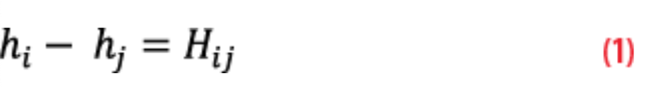
where hi and hj are the clock desynchronization of LFS clocks i and j, Hij is the dual one-way ranging measurement corrected by relativity effects, hardware delays (in meter) relative to the ISL antenna on the receiving chain and on the transmitting chain, and phase centre offset relating on both emitter and receiver satellite [4].
It is therefore possible to construct the clock problem and solve it using various techniques [5-8]. The high quality of the dual one-way ranging measurements, combined with high-quality atomic clocks, allows the construction of a composite timescale whose expected qualities have phase continuity, frequency continuity and high stability (measured by the Allan variance). The SNT is aligned with the GNSS constellation timescale in a conventional manner, either by calculating a timescale difference, a posteriori, or directly during SNT generation by adding constraint equations. This steering will be performed using navigation messages from the GNSS constellations.
The timescale obtained is implicit; it is a paper time because it is calculated as a “well-constructed” average of all the clocks contributing to the calculation. The result of the composite clock algorithms provides biases that represent the advances or delays of each of the LFS clocks relative to the SNT timescale. Once these biases are applied, each clock is assumed to represent a realization of the SNT. This process, therefore, enables the global synchronization of all the LFS in the SBAS system. It then becomes possible to transmit a signal to the constellation every second of the SNT time.
TTA Reduction
The classic implementation of an SBAS (like that of the EGNOS V2 and KASS operational systems) is designed to be a Periodic (repetitive cycle of operations), Synchronous (each operation is performed according to its own timing), and Pipelined (all operations are performed in series) system. Specifically, observations are performed simultaneously at all ground RIMS stations at the second round of GPS time. Data are then transmitted to the navigation cores, where the algorithms are executed at a frequency of 1 Hz as soon as almost all RIMS measurements are received. Each operation has a specific execution time allocation, and the entire system is designed to complete a cycle in 5.2 s.
In the globalized SBAS concept, the LFS also perform measurements in a synchronous manner, meaning all stations observe GNSS events at the same coordinated moment. However, unlike the classic implementation, the specific timing of these measurements is optimized. The synchronization point is not arbitrarily fixed to the second round of system time, but is strategically chosen. This optimization takes several constraints into account: the requirement for the NOF to be available for broadcast starting at a specific round of system time, the estimated data transmission time between LFS, and the computational resources needed to generate the NOF. By aligning the measurement moment with these operational constraints, the system can maximize efficiency and ensure timely availability of the SBAS corrections for end users.
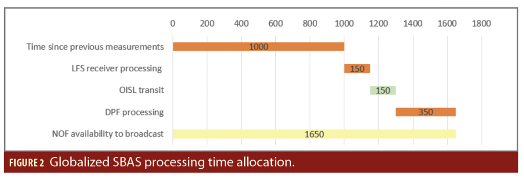
Assuming measurements time is optimized, the time allocations in the different elements of the system would be [9]:
• 1,000 ms to acquire new measurements, due to the 1Hz frequency of NOF broadcasting;
• 200 ms to generate the raw measurements (150 ms) and to format them (50 ms);
• 150 ms to disseminate the data to all SV through the ISLs;
• 350 ms to process data in the DPS (200 ms for computation and 150 ms for exchange data between satellites).
At the end, the NOF ready for broadcast is available in less than 1 second (Figure 2).
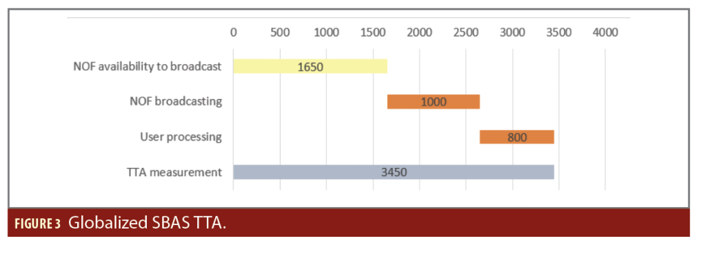
The time to alert (TTA) corresponds to the maximum time elapsed between the moment an anomaly likely to compromise user safety is detected and the moment the user receives the corresponding alert, informing them to no longer trust the service. In other words, it is the maximum time for any fault/error detected or suspected by the system to be reported to users by an alarm message transmitted via the SBAS signal. TTA is a central criterion for safety-of-life applications. For vertical guidance approach services (APV-I / LPV-200 type), the international ICAO SARPS standard sets the maximum TTA at 6 seconds. If the SBAS detects a loss of integrity, the alert must reach the user within this time. A short TTA ensures users will be quickly informed of a loss of performance or an anomaly, and can react or interrupt critical procedures when service reliability cannot be guaranteed.
The TTA takes the duration of NOF transmission (1 s) into account and the time allocated to user processing (800 ms). The time of SBAS signal propagation from LEO to user is neglected in this first apportionment (around 3 ms). The complete SBAS cycle is completed in between 3 and 4 s (compared to 5.2 s in classic case). The TTA is then below 3.5 seconds, representing a reduction factor of two with respect to classic ground SBAS (Figure 3).
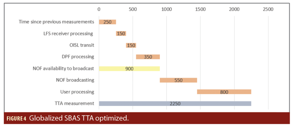
Finally, the concept of fast alert, [9] would be enabled. Fast alert messages are broadcast using the Q-channel and contain the alert flags (alarm/no alarm) for all satellites set in the PRN mask. The complete SBAS cycle is completed in 1.5 s (compared to 5.2 s in a classic case). This operational flexibility would allow a TTA of 2.3 seconds (Figure 4).
LFS Broadcast the NOF
In a conventional SBAS architecture, the NOF is transmitted to users by one or more geostationary satellites. This message is generated on the ground, so it must be encoded into a signal and transmitted by a dedicated RF ground up-link station to the GEO. Because the first bit of the NOF must be sent synchronously at the second round of SNT time (close to GNSS time by specification) at the phase center of the GEO satellite, conventional SBAS systems implement a long loop that controls the signal transmission time to the ground. The SBAS is also endowed with an “integrity box” that checks the NOF return link to ensure the NOF received by the user is the same as the one computed by the system. In most cases, both NOF are strictly equal; if a corruption is detected the integrity box cuts the emission at ground.
In the case of a space-based SBAS system, LFS are capable of transmitting the NOF. To be properly processed in the GNSS receiver computing chains, this signal must be modulated by a PRN code that will spread the carrier spectrum using the Code Division Multiple Access (CDMA) technique. For this signal to be correctly processed within GNSS receiver chains, it must be modulated using a Pseudo-Random Noise (PRN) code, effectively spreading the carrier spectrum via CDMA. There are two primary approaches for assigning PRN codes to the LFSs:
• All LFSs transmit using the same PRN code;
• Each LFS transmits using a dedicated PRN code.
In the first case, the globalized SBAS broadcast the NOF with a single, unique PRN for all LFS transmissions. When multiple LFS are within the receiver’s field of view, the receiver can typically differentiate between transmissions by exploiting distinct Doppler shifts, which result in separate correlation peaks in the time-frequency domain. However, the probability of collision between the two correlation peaks is significant. Assuming a Doppler shift of 50 kHz, a loop bandwidth of 5 MHz and a PRN code of length 1,023 chips, the probability of a collision between two peaks can be estimated as (5.103/5.105)×1/1,023≈10-5 per millisecond, corresponding to roughly one collision per 100 seconds. If three satellites are in view, the likelihood of simultaneous collision among all three signals becomes negligible. Therefore, using a unique PRN for all LFS requires continuous visibility of at least three LFS. However, this approach implies LFS signals cannot be used for ranging: While the NOF message can be received, the receiver cannot distinguish which LFS transmitted it.
In the second approach, each LFS is assigned a distinct PRN code. Currently, GNSS receivers store the navigation contexts of NOF messages received from each GEO SBAS, identified by its dedicated PRN. Out of all recorded contexts, the user applies only one; when the receiver switches PRNs, it replaces the navigation context accordingly and the old one is purged. In the context of globalized SBAS, however, the visibility time of each LFS is very short, about a dozen minutes, which is insufficient for a receiver to fully update its navigation context. In this situation, the user must retain the navigation context when switching PRNs instead of purging it. This ensures seamless continuity for the user; the navigation solution remains coherent regardless of the current LFS because the integrity and accuracy information provided by each NOF is consistent across all LFS. This adaptation necessitates an evolution of SARPS and MOPS standards to accommodate the new PRN allocation schemes envisaged for global SBAS. This approach allows the ranging function to be achieved even if it involves a significant increase in the number of PRNs required.
The NOF is transmitted synchronously at the second round of SNT time. In other words, all LFS transmit the NOF to users at the same second of SNT time. This approach removes the necessity and the complexity of the long loop.
Every second, the system broadcasts a single common NOF according to a fixed and predictive message-sequencing scheme, compliant with the requirements of the SARPS standard. This augmentation message is broadcast in L5-I signal frequency.
The constellation is designed so at least two LFS are visible beyond 5° elevations of any user on Earth. The LFS are assumed to be able to receive GNSS signals in the Radio Navigation Satellite Service (RNSS) band and emitting the Aeronautical Radio Navigation Service (ARNS) band without jamming between emission and reception.
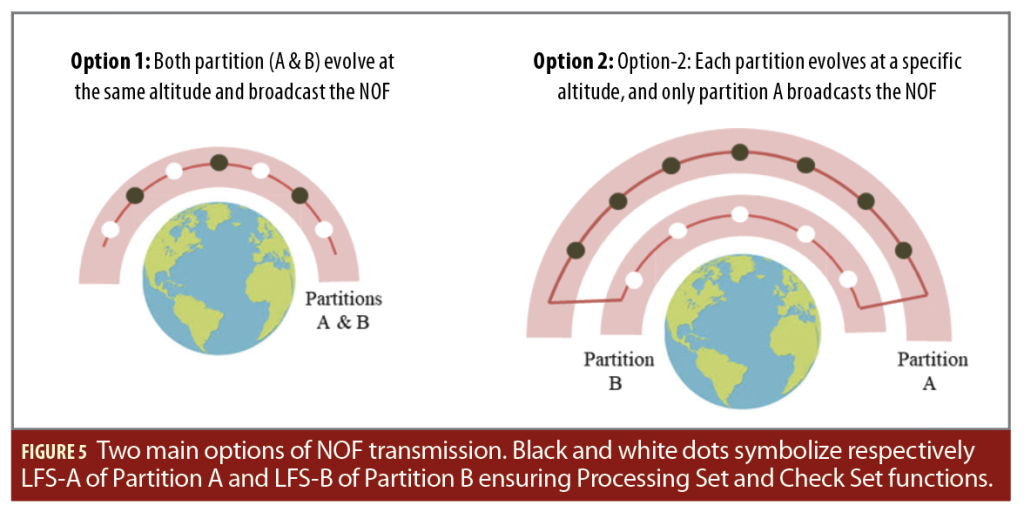
Whereas in conventional systems two or three GEOs are active, the possible loss of a GEO has a direct and immediate impact on availability and service continuity performance over a sometimes large geographical area. This new approach multiplies the number of NOF emission points, which greatly increases the resilience of system performance to this type of failure, reducing the impact to only a few users. Different combinations are possible on the geometric distribution of NOF emission points: in Option-1 the two partitions broadcast the NOF, in Option-2 only one partition broadcasts the NOF (Figure 5).
In Option-1, the two fleets broadcast the NOF. A standard functional allocation would consist in apportioning the same number of satellites to partitions A and B. As the LFS A and B are placed at the same altitude, the LFS-B cannot treat the NOF received as the user will; LFS-B only checks the NOF the system is ready to send the user. As all LFS emit the NOF, the return link function is not possible. Detecting possible NOF corruption (a LFS emits a message not conformed to it specification) is then allocated to the user. If the NOFs are different, SBAS can no longer be used.
In Option-2, partition A is placed above partition B: altitude of the PS function is higher altitude of the CS function and only partition A broadcasts the NOF. The two partitions remain connected by ISL. The difference is now the CS can receive and monitor the NOF messages being sent by partition A and identify whether corruption is possible. The CS identifies the LFS-A responsible for this corruption and sends it a command requiring it to stop sending the NOF. At the next second, this specific LFS-A will cease the emission. The redundancy of LFS-A is designed to limit the impact of this corruption at user level and to maximize the level of performance of availability and continuity.
A global SBAS should bring permanent continuity in GNSS satellite visibility so it can monitor, at any time, all GNSS satellites configured in the PRN mask.
LEO Ranging Function
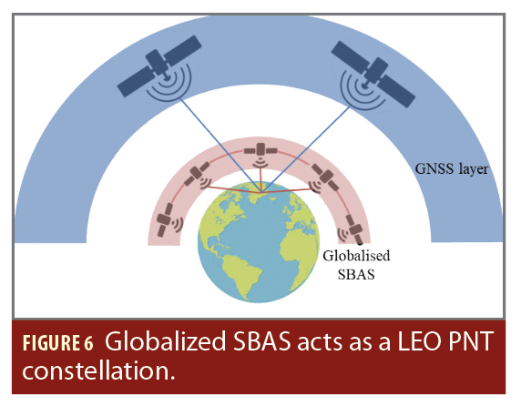
The realization of this function assume seach LFS transmits using a dedicated PRN code. LFS have an independent orbit estimate and are synchronized with each other, giving them the information necessary to fulfill the LEO ranging function (Figure 6). This consists of considering LFS as an additional ranging signal. Consequently, the globalized SBAS can naturally act as a LEO PNT system:
1. The satellite precisely synchronizes the start of a PRN code sequence transmitted in the signal with the start one second of SNT time,
2. The satellite synchronizes the first bit of the navigation message with the second round of SNT time,
3. The satellite maintains synchronization of the start of a navigation bit with the start of a PRN code sequence,
4. The satellite maintains the code-carrier consistency.
The internal navigator of the LFS provides an orbit and a clock synchronization bias relative to the SNT. Orbitography algorithms also provide a variance-covariance matrix that can be used to provide URA data. A suitable ARAIM concept could provide the integrity of LEO satellite navigation data, allowing LEO ranging measurements to be incorporated into a safety-of-life solution. The LFS navigation message shall be encoded in the signal broadcast to the user.
In the classic SBAS paradigm, GEO-Ranging function is possible and GEO data navigation takes place inside the NOF itself (MT9 dedicated for GEO SBAS L1 ephemeris). In the spatialized SBAS paradigm, the number of transmitting satellites is increasing considerably and inserting LEO navigation data into the NOF would congest the available bandwidth. It is better to transmit the SIS ranging data in a dedicated message rather than the NOF. In this aspect, two options are envisioned: either LEO ephemeris are encoded in L5-Q signal frequency or L1-I signal frequency. The first is the most energy-efficient because one signal is generated on L5, which modulates the NOF on the I channel and the ephemeris on the Q channel. The second option requires generating and transmitting two signals on two different frequency bands, which consumes more energy and adds complexity. Users can leverage these two frequencies to form the iono-free combination, as is done with GNSS satellites, and improve their positioning.
Monitoring and Control
Classic SBAS provides system monitoring and control, which involves overseeing and managing the ground segment subsystems, supporting maintenance tasks—including configuration management—offering data archiving capabilities for offline activities, and enabling communication with external entities.
In spatialized SBAS, the need for the system monitoring and control function is still present: it is even mandatory to operate the system. The operator ensures operational management of the system, maintenance of the infrastructure and supervision of the service provided to users. Several Mission Control Centers (MCC) on ground are necessary for this. The MCC and the LFS constellation communicate with each other by classic TM/TC.
LEO Constellation Infrastructure
Achieving a worldwide SBAS solely through ground stations is impractical due to the necessity of comprehensive global coverage, which would require an immense and continuously maintained network of ground infrastructure spread across the entire Earth’s surface. This makes it difficult to provide consistent, reliable augmentation signals everywhere.
Deploying space-based stations in LEO orbits offers a more efficient and effective solution. LEO satellites can cover vast areas of the planet from orbit, overcoming environmental masking faced by ground stations. This space-based approach ensures continuous, global augmentation service with improved scalability, making it preferable for establishing a worldwide SBAS.
Another benefit of the LEO constellation, and a consequence of global coverage, is its unique capability to receive measurements from GNSS satellites throughout their entire orbits, regardless of the satellites’ position relative to the Earth’s surface. This comprehensive
visibility enables LEO satellites to monitor GNSS signals continuously, eliminating geometrical blind spots that can occur when relying on ground stations. The estimation of GNSS satellite orbits and clock errors becomes more accurate and robust, leading to improved navigation performance. By providing consistent and diverse observational data from multiple vantage points in space, LEO constellations significantly expand the precision and reliability of GNSS orbit and clock determination. This visibility is the main driver of constellation size: ensuring at least one LEO satellite is visible at all times everywhere on Earth is required to receive the NOF message. Given the safety-of-life nature of the system, safety guidelines further recommend a minimum of two LEO satellites be visible at all times everywhere to cover a single satellite failure. Visibilities are considered when the satellite is above 5° of elevation above the horizon.
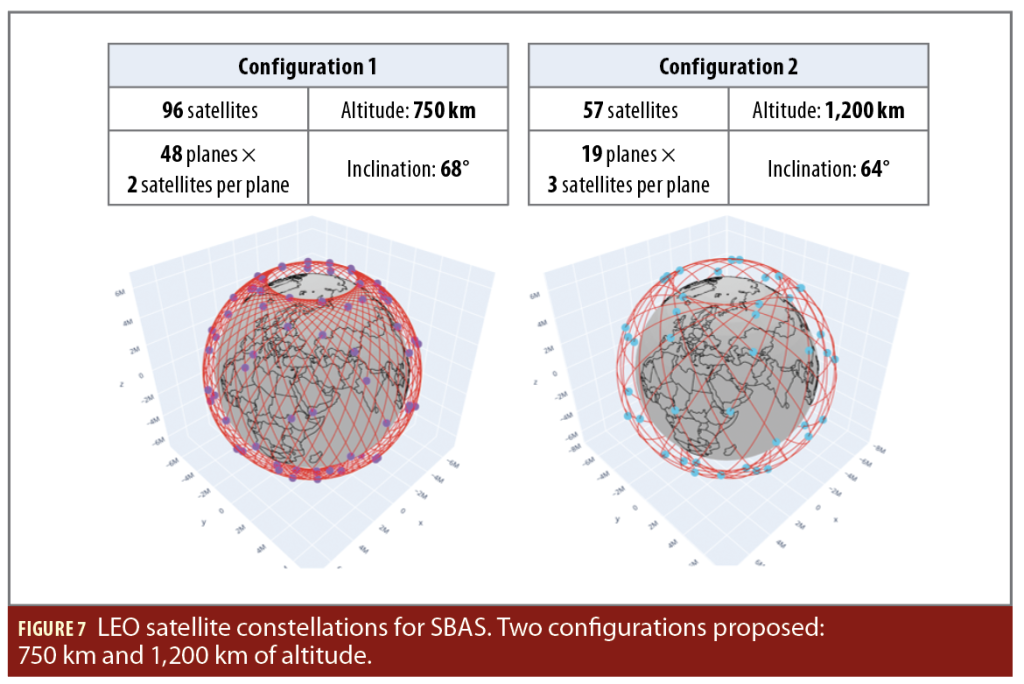
The characteristics of a LEO constellation satisfying this constraint mainly depends on altitude. For this study, two different altitudes are considered:
• 750 km of altitude. This leads to a constellation made of 96 satellites.
• 1,200 km of altitude. This leads to a constellation made of 57 satellites.
These constellations are designed to ensure a minimum number of satellites to respect geometric constraints. They do not constitute the real constellation that will necessarily be sized to take into account failures, redundancy, etc.
These two LEO constellations are configured and represented in Figure 7.
For each altitude considered, the constellation is minimal in terms of number of satellites. Any constellation with fewer satellites does not ensure at least two satellites in visibility at all times.
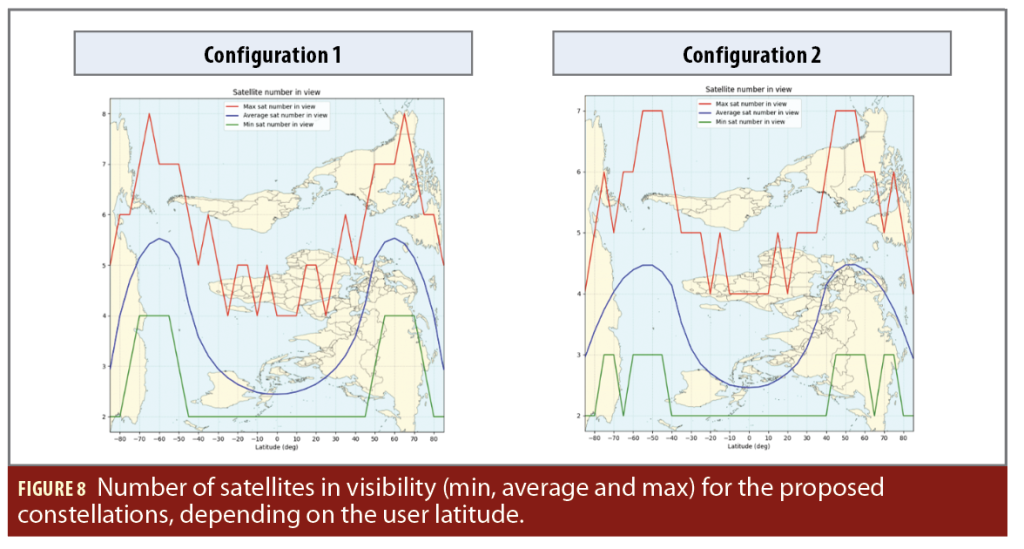
The visibility constraint can be verified by using a simple simulation. Visibilities are calculated for a grid of users on Earth. However, as the LEO satellites have an orbital period between an hour and a half and two hours, they make around 15 orbits on a single day. This means globally, the visibility statistics are the same for all users on a same latitude. Therefore, the results in Figure 8 show the minimum, average and maximum number of satellites in visibility as a function of latitude.
The constraint of at least two satellites in visibility is satisfied everywhere. The statistics do not differ significantly between the two constellations, with visibilities being minimum at the equator, increasing for higher latitudes and decreasing near the poles.
A LEO satellite used for a safety-of-life system will have associated constraints in terms of certification and will be costly. So, the number of satellites should be minimized, making the constellation at 1,200 km the seemingly preferred option. However, this criterion should also be in balance with criteria related to the satellite payload, onboard available power, antenna design, launching constraints and end-of-life constraints. A higher altitude means satellite signals will have to be transmitted with a higher power. The launchers will need to reach a higher altitude, and deorbiting the satellites when they reach their end of life will require more manoeuvring capabilities. This all must be taken into account, but it is also very dependent on satellite platforms, payloads and launching capabilities.
Distributed Processing Facility
Space-based computing
Space-based computing has been increasingly taken into consideration over the past few years. Among others, we mention the innovative EU-funded study Advanced Space Cloud for European Net zero emission and Data sovereignty (ASCEND) [10], which focuses on the feasibility of deploying space-based data centers and relying on space-based cloud based solutions [11].
In May 2025, China launched the first 12 satellites of a planned 2,800-strong orbital supercomputer satellite network. These satellites aim at performing calculations in space without relying on any ground-based computing facility.
Computing in space offers three major advantages compared to traditional ground-based systems:
• Reduced data transmission costs: Processing data locally in space reduces the need to downlink large volumes of data to Earth, saving bandwidth and costs;
• Low latency: The mutual proximity of satellites in the constellation reduces communication delays, enabling faster data processing;
• Scalability: Space-based cloud computing can potentially scale by deploying additional resources (later named spare satellites) and can be reconfigured dynamically.
A centralized space-based solution
A straightforward route to designing an efficient space-based processing facility is to rely on a centralized space-based solution, where an independent and already in place infrastructure located in space hosts the entire calculation. This solution exploits already existing algorithms and relies on computing infrastructures currently used on ground-based systems. Nevertheless, this easy to follow route faces the following three main challenges:
• Single point of failure: The entire computing system relies on a single dedicated platform. This means any hardware or software failure can disable the entire computing capability, unless duplicate/diversified computing capabilities are incorporated into the constellation. This expensive solution makes the global infrastructure rather complex.
• Communication: All data must be routed to and processed by the centralized unit, which represents a major bottleneck in terms of communication and elapsed times before calculation. High communication loads may significantly reduce real-time responsiveness;
• Energy inefficiency: A centralized computing solution may require high power consumption for processing large data movement within the single dedicated infrastructure. This may create additional energy constraints.
A fully distributed space-based solution
For all these reasons, an alternative solution must be proposed. In a fully distributed space solution, each satellite in the LFS constellation corresponds to a specific node of the distributed computing facility. Each satellite of each subconstellation acts as a computational unit and communication between the different nodes is handled by ISL links.
With at least two LFS visible beyond 5° elevations of any user on Earth, the estimated total number of satellites of the global constellation is bounded by 96. Because half of the LFS are attributed to the augmentation message, the total number of nodes of the computing facility is bounded by 48. This moderate network size for a distributed computing facility allows state-of-the-art parallel algorithms to be employed to compute and broadcast messages [12] [13]. At first sight, distributed computing offers immediate advantages over a centralized solution:
• Efficiency: Multiple nodes can handle different computations concurrently. This speeds up the overall computation of navigation messages with respect to a centralized solution, where communications may become a significant bottleneck;
• Fault tolerance: Because processing is spread across multiple nodes, random failure of one node does not necessarily harm the entire navigation system. Other existing nodes of the LFS-A subconstellation may take over degraded tasks. This flexibility is one of the main advantages of the distributed computing solution. Additional spare satellites also may be incorporated into the LFS-A subconstellation to improve fault tolerance.
• Redundancy: Distributed systems can implement both hardware and software redundancy more naturally by duplicating specific critical functions across multiple nodes, reducing potential single points of failure resulting from random failure.
The distributed computing facility relies on the core idea that each node performs a specific part of the computational workload and exchanges messages (possibly with each other) through ISL links. At the end of the procedure, the results are gathered by each LFS to generate a common navigation context. This may induce a potentially high volume of point-to-point or collective communications between the nodes of the LFS-A constellation. Therefore, it is of outmost importance to rely on algorithms that minimize the global volume of communication. The computation of the state vector during the filtering process in the PS function provides an instructional example in this regard. Of interest is a parallel algorithm for the solution of least-squares problems that requires a low volume of communication. Does this orthogonal factorization distributed algorithm exist at all?
The answer to this question is positive if we rely on advanced numerical linear algebra methods for the solution of least-squares problems. In our context, a parallel algorithm named Communication-Avoiding QR (CAQR) is worth considering [14]. CAQR is a class of QR orthogonal factorization algorithms designed to minimize (and not avoid) the costly communication between nodes in distributed systems. Because data movement often dominates the energy consumption and runtime of numerical algorithms, CAQR aims at improving both performance and energy efficiency by reducing the communication overhead. Communication in our context includes data transfers, which are often more expensive (in time and energy) than arithmetic operations [12]. This reduction of communication overhead is obtained through a specific factorization: CAQR typically divides the matrix to be factorized into different panels (i.e. blocks of columns). Instead of applying the classical Householder QR method [15], [16] on the panel, CAQR applies Tall-Skinny QR (TSQR) [17] instead, a specific QR factorization. TSQR minimizes communication by recursively factorizing smaller blocks, using a reduction tree structure (e.g., a binary tree of partial QR factorizations) to combine results efficiently with limited data movement [18] [19]. In short, communication costs are reduced by organizing QR operations as tree-structured reductions rather than linear sequences. This algorithmic feature enables parallel processing of independent blocks, combining partial results with minimal communication steps. The number of communication steps is logarithmic in the number of panels [20].
By significantly reducing the volume of communication, CAQR delivers a reduced energy consumption while providing improved overall runtime [14]. CAQR maintains the numerical stability properties of classical Householder QR factorizations, ensuring accurate and reliable factorization results despite the communication optimizations. At the end of the algorithm, the solution of the least-squares problem is known on a leaf of the reduction tree and a single collective communication is used to share this information on the other nodes of the LFS-A subconstellation. This shows a distributed algorithm with a low overhead in terms of communications can be applied during the filtering process.
Space-based distributed computing is a doable approach that introduces additional constraints to satisfy during the design of the architecture of the spatialized SBAS:
• Limited computational resources: Each node has a specific limited CPU (or GPU) power, memory and energy compared to Earth-based computing centers. A key point is to optimize the global hardware resource efficiency with respect to the properties of the LFS-A subconstellation (number of satellites and total volume of communication essentially);
• Physical and environmental constraints: Space-based computing often meets challenging physical conditions (such as temperature extremes, vibration, radiation in space) that may affect hardware reliability. Hardware must be resilient against environmental factors. A key point is to overestimate the number of satellites in the LFS-A subconstellation to provide redundant calculations.
These additional constraints must be carefully considered when designing the global constellation and when performing the safety analysis.
Safety Dimensioning in New SBAS Architecture Concepts
When analyzing novel SBAS architectural concepts from a safety standpoint, it is imperative to recall the overarching safety dimensioning principles to guide the assessment of their compliance and the identification of associated constraints.
This analysis is framed within the context of civil aviation. At the system level, the primary safety-feared events and their corresponding severity classifications are defined as:
• Integrity is customarily established as the measure of the trust that can be placed in the correctness of the information supplied by a navigation system. Integrity includes the system’s ability to provide timely warnings to users when it should not be used for navigation. A failure in integrity, termed a “non-integrity event,” is linked to a hazardous severity classification [21].
• Continuity is the ability of the total system (comprising all elements necessary to maintain craft position within the defined area) to perform its function without interruption during the intended operation. More specifically, continuity is the probability the specified system performance will be maintained for the duration of a phase of operation, presuming the system was available at the beginning of that phase. A “non-continuity event” corresponds to a major severity classification [21].
Foundational Safety Engineering and Safety Assurance Principles
The applicable European Cooperation for Space Standardization (ECSS) standards in Europe stipulate that “no single system failure or single operator error (SPOF) shall have critical (i.e. hazardous) or catastrophic consequences.” This has profound architectural implications; it requires that any function whose failure could result in critical/hazardous consequences must be underpinned by a minimum of two independent components.
Development Assurance Level (DAL)
Given the safety-critical nature of civil aviation, software development is governed by rigorous standards. Safety analyses underpin the allocation of Development Assurance Levels (DAL) to various items in accordance with the architecture.
Development Assurance involves specific planned and systematic actions providing confidence that errors or omissions in requirements have been identified and corrected to the degree the system implemented satisfies the applicable safety requirements. System/sub-systems and products are assigned DALs based on failure condition classifications associated with system level functions implemented in the sub-systems and products. The rigor and discipline needed in performing the supporting processes vary corresponding to the assigned development assurance level.
The initial software DAL determined can be mitigated when considering the different kinds of protections or alternate potential design implemented into the architecture, with provision that evidence of full independence between involved software functions is provided. Finally, the DAL allocation is a consequence of the implemented architecture: The redundancy, independence, and segregation embedded within the architecture dictate the refinement of DAL assignments. DAL levels play a pivotal role in component selection and exert a significant influence on project costs. It is prudent to iteratively assess candidate architectures to converge upon an optimal solution.
Software failures with potential hazardous implications (e.g., non-integrity events in SBAS) necessitate DAL B [22]/SWAL 2 [23].
Software failures leading to major events (e.g., non-continuity events and Accuracy Major event in European SBAS) require DAL C [22] / SWAL 3 [23].
In typical SBAS architectures, functions contributing directly to the integrity check of augmentation messages and certain critical data dissemination tasks—those that guarantee the non-corruption of broadcast messages—are assigned DAL B, in recognition of their integrity-related criticality. Conversely, functions related to data collection and non-critical dissemination generally carry a DAL C assignment in Europe, reflecting their continuity focus.
Emitted SBAS Signal Monitoring
For any safety-critical system intended for safety-of-life applications, the following principle remains salient: Wherever possible, the SBAS system should internally monitor its own transmitted signal, permitting real-time awareness of failures (primarily those in the dissemination chain) and take adequate actions instead of relying on open-loop operation. While not a formal requirement provided other safety principles (in particular the SPOF principle) are observed, this best practice is inherent to the present concept.
Implementation of Safety Principles in Operational European SBAS EGNOS V2
These foundational safety principles are stringently applied in the operational European EGNOS system, with their fulfillment evidenced across the following major functions:
Data Collection: EGNOS V2 employs physically and logically separated RIMS A and B chains, both developed according to DAL C1.
• Augmentation Message Calculation and Integrity Checking: The Central Processing Facility (CPF), assigned DAL B1, comprises two independent units fed by independent data: the PS fed by RIMS-A and the CS fed by RIMS-B. In accordance with [22], the PS is allocated DAL C1 and the CS receives DAL B1. This dual-channel design directly supports enforcement of the SPOF principle.
• User Dissemination: The operational SBAS in Europe relies on NLES and GEO segments. Safety-critical integrity related functions—such as CPF selection and Integrity Check— are segregated and allocated DAL B. Functions that contribute primarily to continuity rather than integrity are assigned to DAL C1.
The integrity check function—which continuously verifies the fidelity of the broadcast NOF via the Integrity Box—effectively upholds the SPOF principle by precluding integrity events stemming from a single failure or corruption of the NOF within the dissemination chain. This mechanism ensures continuous monitoring of the emitted SBAS signal, empowering the system to respond appropriately in the event of any dissemination anomaly.
Complementing this capability, GEO signals as received at the RIMS, are relayed to the CPF, facilitating the prompt issuance of alarms or corrective actions whenever discrepancies are identified. Should a failure—specifically, NOF corruption—arise within the dissemination chain (in cases where the chain does not broadcast the information as instructed by the CPF), it is possible that, even if the CPF detects the anomaly and generates alarms, these messages might not be transmitted due to the compromised dissemination chain. The integrity check function is designed to address this scenario.
Compliance of the Fully Space-Based SBAS Concept with Safety Requirements
At the system level, from a safety perspective, the high-level architectural proposal is summarized in Figure 9.
At the system level, the architecture preserves the logic of maintaining two independent channels—extending from data collection through correction computations and integrity checks. This dual-channel strategy ensures adherence to the SPOF principle at the highest level. Specifically, LFS-A is dedicated to feeding the PS, whereas LFS-B supplies the CS. The strict separation between LFS-A and LFS-B guarantees the independence of input data for each critical process.
The correction PS, sourced from LFS-A, is entrusted with generating corrections and the associated integrity bounds. In parallel, the CS leverages independently sourced measurements from LFS-B to validate the corrections and their integrity parameters. This rigorous, independent, dual-channel design ensures a single fault or failure cannot compromise overall system integrity.
For data collection, several considerations stem from safety recommendations. Positioning GNSS data collection stations is critical for the calculations performed by the SBAS processing system. Leveraging mobile GNSS data collection stations introduces the necessity to strictly ensure the accuracy of their geospatial coordinates. To safeguard against error or bias propagation, the positioning solution for LFS stations should be established using means and data independent from those employed by the SBAS system itself. This mitigates the risk that systematic biases or errors could be inadvertently transmitted into the final positions computed by the SBAS. Solution 3 (“LFS orbits are calculated using independent means and independent measurements”) directly fulfills this requirement for independence. In addition, leveraging ISL connectivity with ranging capabilities further increases and consolidates the accuracy of LFS location estimates.
Deploying two distinct fleets—LFS-A and LFS-B—allows separation between correction computation and integrity verification channels. With their positioning, LFS-A and LFS-B will achieve substantially different observation geometries; the system hence ensures data streams used for corrections and integrity bound computations and those for integrity checks remain independent, enhancing the robustness of integrity check.
Analogously to the RIMS DAL C allocation within “terrestrial” SBAS systems—attributed for their respective contributions to continuity—the data collection function is designated a DAL C1.
With respect to data processing and integrity verification, the principle underpinning this architecture is to preserve complete independence between the PS and the CS, upholding the SPOF criterion. To this end, the PS and CS are provisioned with independent inputs from LFS-A and LFS-B respectively, each implementing diversified algorithms purposed to detect and mitigate feared events, initiate appropriate alarms when required, and compute/verify corrections and associated integrity bounds.
Drawing upon a safety monitoring principle [22] that’s applied within operational EGNOS V2, the PS is allocated DAL C1, whereas the CS receives a DAL B1 allocation. These designations impose considerable constraints on software development for the LEO satellite segment.
Both the PS and the CS are proposed under the paradigm of a “fully distributed space-based solution,” whereby the PS function (and likewise the CS function) is performed by an “active sub-pool” of LFS-A (and, correspondingly, of LFS-B). Owing to the permanent communication links established among all LFS units, any failure occurring within one of the active sub-pool LFS nodes is instantaneously propagated. This enables the swift activation and integration of a replacement LFS into the active sub-pool for a given PS/CS sub-function. Thanks to the scale of the constellation, the computational resources available to each LFS unit, and—critically—the capability afforded by the ISL that ensures all LFS nodes maintain an identical level of information, the system can exploit “hot redundancy” among LFS nodes for PS and CS sub-function. This design enhances the overall availability and continuity of the global system.
The concept’s reliance on transmitting a singular, uniquely defined NOF stream simplifies redundancy management across both user receivers and within the system’s own infrastructure.
It is noteworthy that the alternative logic of a “centralized space-based solution” is not inherently prohibitive from a safety perspective. While such an approach does introduce a central point of failure from a RAMS standpoint, this vulnerability can be mitigated by implementing robust redundancy architectures or, if needed, diversified processing chains. Such design adaptations could render the centralized solution sufficiently resilient, thereby restricting its adverse impact on system availability and continuity.
The dissemination of the NOF concept entrusts the LFS with dissemination responsibilities, diverging from the conventional reliance on GEO satellites typical of SBAS.
Broadly, a failure within the dissemination chain may precipitate:
• A continuity event, triggered by loss of functional capability;
• An integrity event, arising from corruption of the NOF by the LFS.
In the first scenario, loss of a single LFS impacts availability and continuity, but these consequences are geographically constrained and limited to a small subset of users (in marked contrast to the loss of a GEO satellite), rendering such events generally acceptable.
Conversely, in the event of NOF corruption by an LFS, a potentially significant integrity event may ensue. Owing to the density of the LEO constellation, comprehensive real-time monitoring of all NOF transmissions from all LFS assets is unfeasible for the SBAS system. As a consequence, a single undetected failure could compromise system integrity. The safety concept herein articulated recommends users monitor at least two independent LFS sources and cease using the service if discrepancies are detected between the NOF received from these sources.
This mitigation is not considered fully satisfactory from a safety standpoint. First, it does not necessarily protect against all types of dissemination failures, such as systematic software faults affecting LFS-A, which could lead to correlated failures across seemingly independent units. Secondly, it places the burden of integrity monitoring on the user, exposing a fundamental limitation in the system’s intrinsic ability to autonomously detect and respond to dissemination failures—which is not optimal from a safety perspective.
Option-2 offers a different approach, whereby the NOF broadcast from LFS-A is subject to independent monitoring by a separate LFS-B asset, typically operating at a lower orbital altitude. In this arrangement, LFS-B would possess the authority to inhibit or terminate transmissions from LFS-A if an inconsistency or corruption in the NOF is detected. This monitoring of the LFS-A by the LFS-B would be DAL B allocated.
Additional Safety Considerations and Way Forward
These safety considerations do not identify any fundamental showstoppers to the global SBAS concept using a fully space-based infrastructure. This concept eliminates de facto classic local ground effects such as multipath, interference, tropospheric delays, and tidal effects, improving performance. Nevertheless, several broader points must be explored:
Applicable SBAS Regulatory Framework
The safety reference framework and associated requirements considered are currently in force for SBAS within Europe. One major consequence of this regulatory baseline is the requirement for dual, fully independent “A” and “B” chains—most notably, the need for PS and CS functions to be separated and developed respectively to DAL C and DAL B. In particular, the imposition of DAL B on software development for LEO satellites may result in very significant development costs.
The SPOF principle for critical/hazardous events, as inherited mainly from ECSS, appears to be more stringent than those applied in the aeronautical domain. A review of [21] reveals:
• No explicit “no SPOF” criterion for hazardous failure conditions;
• No requirement that no combination of two independent system failures or operator errors should lead to catastrophic consequences (required by the ECSS).
Notably, aeronautical standards demand the absence of SPOF only in the case of catastrophic consequences. In Europe for a SBAS, the requirement for no SPOF in critical/hazardous systems may be justified by the large number of aircraft potentially affected by any failure—a rationale that arguably holds even greater weight for a global system of this nature.
Applying the SPOF principle at the critical/hazardous level mandates the implementation of two independent chains for the CS and PS. It would be relevant to analyse this architecture and corresponding DAL allocation in light of the [24] guidelines (which are not part of the European baseline for SBAS). According to [24], if a hazardous failure condition could result from a combination of possible development errors between two items, either one should be allocated at least DAL B, or both should be assigned DAL C. This latter approach could offer a more balanced allocation of development assurance levels and potentially alleviate some of the stringent constraints currently imposed on LEO satellite software development.
With regard to implementing the approach outlined in [24], the current concept involves exchanges between the PS and CS chains. In particular, the function responsible for generating corrections and integrity bounds is not fully duplicated across both PS and CS chains. Should the current level of independence between PS and CS be insufficient to comply with the principles set forth in [24], minor modifications to the concept could be considered. For instance, the PS functions could be integrated within the LFS-B, with dissemination of information also performed by the LFS-B (as in Option 2). In this case, two NOFs would be distributed, and a voting mechanism at the user level would help identify an erroneous NOF. However, this scenario would lack monitoring of the NOF broadcasted by the LFS-B to the user.
Identification of New Feared Events Arising from Spatialization
Introducing “fully based” elements—specifically the implementation of ISL, using the DORIS system, and the spatialization of equipment that is traditionally ground-based in an SBAS—should lead to identifying new internal feared events to address in the system-level analysis.
Global System Considerations
The core strength, innovation and advantage of this concept lie in its potential to provide truly global coverage for integrity services. The positive implications of such an advancement would be substantial, but it’s necessary to address questions regarding responsibilities and roles among different countries, particularly given the safety-critical nature of the service on a worldwide scale.
Conclusions
This article explores a groundbreaking shift in SBAS architecture by proposing the spatialization of its core components—data collection, augmentation message computation and dissemination—within a distributed network of LEO satellites. By moving reference stations into orbit as LFS, the system achieves global GNSS visibility, eliminates the constraints imposed by terrestrial station distribution, offers a worldwide service, and significantly enhances the accuracy and resilience of navigation augmentation data.
The architecture leverages advanced technologies like inter-satellite links and space-based distributed computing, enabling real-time data sharing, independent time scale generation, and robust integrity monitoring. The proposed partitioning of the constellation further meets stringent safety-of-life requirements, ensuring redundancy, diversity of observations, and fail-safe operations.
Simulation results demonstrate that appropriately sized LEO constellations can guarantee continuous visibility and redundancy for service availability, while the distributed processing facility uses state-of-the-art parallel algorithms to minimize communication overhead and maximize computational efficiency. While the technical feasibility is affirmed, the design must also accommodate the unique constraints of space infrastructure—including hardware resilience, energy consumption and operational safety.
Overall, this study shows that a globalized, space-based SBAS could offer transformative improvements in augmentation accuracy, reliability and scalability—paving the way for a next-generation system capable of meeting the demanding needs of civil aviation navigation on a truly worldwide scale. Future work will focus on refining the constellation design, optimizing system safety, and addressing the operational and certification challenges inherent to spaceborne navigation augmentation.
Acknowledgment
The authors thank Michel Monnerat for discussions regarding receiver signal processing and Celine Renazé for her useful advice and recommendations.
References
[1] ICAO Standard and Recommended Practices (SARPs), Annex 10, Volume 1, up to Amendment 93
[2] D. Flament, J. Poumailloux, J-L. Damidaux, S. Lannelongue, J. Ventura-Traveset, P. Michel, C. Montefusco, “The EGNOS System Architecture Explained”, May 2011.
[3] User Guide for EGNOS application developers, Ed. 2.0, 15/12/2011, ISBN 978-92-79-20335-0 ESA.
[4] M. Laurenti, L. Maisonobe, P. Roldan, J. Anton, P. Guerin, S. Trilles, “Improving GNSS Navigation Messages Performance using Inter Satellite Links Technology”. Inside GNSS May/June 2024, pp 36-42
[5] Brown, K. R. (1992). The Theory of the GPS Composite Clocks, Proceedings of ION GPS-91, 11-13 September 1991, pp. 223-242.
[6] Greenhall, C. A. (2007). A Kalman filter clock ensemble algorithm that admits measurement noise: corrections and update, Metrologia, 44, 491-494, doi:10.1088/0026-1394/44/6/008
[7] Senior, K. L., & Coleman, M. J. (2017), The Next Generation GPS Time, NAVIGATION: Journal of The Institute of Navigation
[8] Roldan, P., Trilles, S., Serena, X., Tajdine, A., “Novel Composite Clock Algorithm for the Generation of Galileo Robust Timescale,” Proceedings of ION GNSS 2022, September 2022, pp. 2790-2799. https://doi.org/10.33012/2022.18521
[9] C. Renazé, C. Bourga, M. Clergeaud, J. Samson, “Reduction of system time to alert on SBAS”. Inside GNSS, November-December 2023, pp 28-36
[10] https://ascend-horizon.eu/
[12] G. Hager and G. Wellein, “Introduction to High Performance Computing for Scientists and Engineers”, CRC Press, 2011.
[13] P. Pacheco and M. Malensek, “An Introduction to Parallel Programming”, 2nd Edition, Morgan Kaufmann, 2021.
[14] J. Demmel, L. Grigori, M. F. Hoemmen, and J. Langou, “Communication-optimal parallel and sequential QR and LU factorizations”, SIAM Journal on Scientific Computing, Vol. 34, 1, pp. A206-A239, 2012, https://doi.org/10.1137/080731992
[15] Å. Björck, “Numerical Methods for Least Squares Problems”, 2nd Edition, SIAM, 2024.
[16] G. H. Golub and C. F. Van Loan, “Matrix Computations”, 4th Edition, Johns Hopkins University Press, 2013.
[17] M. F. Hoemmen, “Communication-avoiding Krylov subspace methods”, PhD thesis, University of California at Berkeley, 2010.
[18] E. Agullo, C. Coti, J. Dongarra, T. Hérault and J. Langou, “QR factorization of tall and skinny matrices in a grid computing environment,” 2010 IEEE International Symposium on Parallel & Distributed Processing (IPDPS), Atlanta, GA, USA, 2010, pp. 1-11, https://doi.org/10.1109/IPDPS.2010.5470475.
[19] G. Ballard, J. Demmel, L. Grigori, M. Jacquelin, N. Knight, H.D. Nguyen, “Reconstructing Householder vectors from Tall-Skinny QR”, Journal of Parallel and Distributed Computing, Volume 85, pp. 3-31, 2015. https://doi.org/10.1016/j.jpdc.2015.06.003.
[20] J. Dongarra, L. Grigori and N. Higham, “Numerical algorithms for high-performance computational science”, Philosophical Transactions of the Royal Society A: Mathematical, Physical and Engineering Sciences, 378(21666), 2020. https://doi.org/10.1098/rsta.2019.0066
[21] CS-25 – European Union Aviation Safety Agency Certification Specification for Large Aeroplanes.
[22] ED-12B/DO-178B – Software Considerations in Airborne Systems and Equipment Certification
[23] ED-109A/DO-278A Software Integrity Assurance Considerations for Communication, Navigation, Surveillance and Air Traffic Management (CNS/ATM) Systems
[24] ARP4754B – Guidelines for Development of Civil Aircraft and Systems
Authors
Sébastien Trilles is an expert in navigation algorithms and performances. He received his Ph.D. degree in Pure Mathematics from the Paul Sabatier University and an Advanced M.S.in Space Technology from ISAE-SUPAERO. He heads the Performance and Processing Department where high precise navigation algorithms are designed as orbitography, system reference time generation, clock synchronization and time transfer, integrity and ionosphere modeling.
Thierry Authié is a specialist in navigation algorithms at the Performance and Processing Department of Navigation Domain, Thales Alenia Space. He received his M.S in Applied Mathematics from the Institut National des Sciences Appliquées (INSA), Toulouse (France). He currently works as navigation specialist in Advanced Projects.
Xavier Vasseur is a specialist in scientific computing at the Performance and Processing Department of Navigation Domain, Thales Alenia Space. He received his M.Sc degree from Ecole Centrale de Nantes (France) and his Ph. D. degree in Computational Fluid Dynamics from University of Nantes.
Marie Abbal is safety manager of Advanced Projects in Navigation Domain. She received her M.Sc degree from Ecole des Mines de Paris. She worked from 2009 to 2016 at Electricité de France company (EDF), particularly in nuclear safety. She joined Thales Alenia Space in 2016 as a safety specialist in complex and critical space system


