This article presents the authors’ experience in setting up an airborne pseudolite (UAVlite) with the needed ground-based infrastructure to perform code and phase ranging performance analysis. UAVlites transmit GNSS-like signals free from any local transmitter multipath (in contrast to ground-based transmitters) and can in principle be localized in real-time through a synchronized network of ground stations which may also broadcast the UAVlite positions in real-time. Furthermore, software defined radio allows for the easy broadcast of new navigation signals and testing them in real environments. In this first step, the key technology elements are verified with one UAVlite, two ground stations, and a CBOC signal. Decimeter code range accuracy and millimeter phase range accuracy has been demonstrated.
There is an increasing importance for GNSS open services for our economy, society, and security, e.g., in the field of traffic monitoring and controlling, be it in the air, at sea, or on land, or in first aid response in any kind of emergency, as well as for timing applications like bank transactions or power grid synchronization. Due to these developments, it is necessary to enhance the availability and more importantly the reliability of GNSS services. Improving the signal robustness against multipath, jamming, spoofing, and interference from secondary sources or even from other constellations is a crucial task for future research and development. To improve GNSS signals, it is crucial to test and analyze the signal performance under various conditions and harsh environments. This was and is done mainly with computer simulations. These simulations are easy and cheap to realize as well as flexible and repeatable. However, a simulation always relies on assumptions and simplifications of a real-world problem. Therefore, we are developing a flexible, cost-efficient, and highly adjustable test system, usable for real test scenarios. With this system, we can investigate the GNSS signal structures, range performance, authentication methods, channel coding, and signal behavior under foliation, blockage, jamming, spoofing, and other interference.
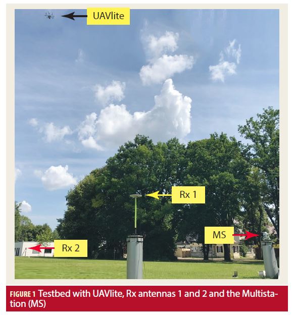
The upcoming interference challenges for GNSS require a detailed analysis on the GNSS signal level. Therefore, a testing method is needed which goes beyond the possibilities of simulations to create a realistic and flexible test environment. The progress in unmanned aerial vehicles (UAV) and software defined radio (SDR) technologies obtained in recent years provide this efficient and flexible approach to mimic GNSS satellites and create an innovative GNSS signal performance testbed in a real environment. Besides UAV and SDR, our system includes a positioning and ranging unit to obtain the transmitter-receiver ranges in sub-centimeter and millisecond timestamp accuracy. Furthermore, two receiving antennas (Rx) with attached front-ends (FEs) are needed, see Figure 1. With the time synchronized FEs and the knowledge of the true transmission position, it is possible to eliminate the transmission clock error and analyze the code and phase ranging performance of every GNSS signal of interest.
After a detailed presentation of the concept, and an explanation of all relevant components, the performance analysis of the ground system is discussed. Thereafter, we discuss the performance analysis of our UAVlite CBOC signal for different power levels. We conclude with a summary and an outlook.
Concept
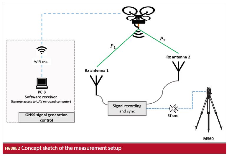
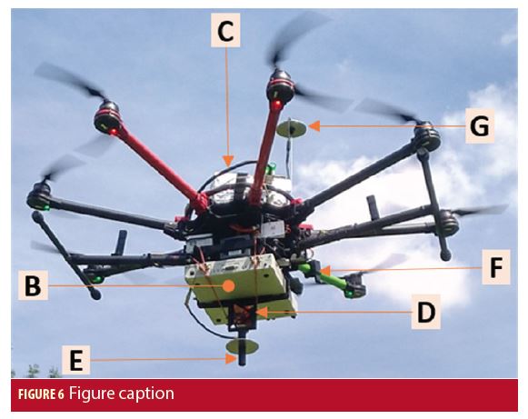
The airborne pseudolite (UAVlite), see Figure 6 in a later section, is composed of a UAV with an SDR and a mini PC as payload. The ground system includes two receiving antennas with a distance of around 40 meters apart from each other. The antennas are connected to clock-synchronized FEs with software receivers. In this way the two incoming signals are both tracked and processed with the same receiver clock and receiver clock error (drift) (see Figure 2). With the two code measurements, it is possible to eliminate the clock error from the SDR (dtsv) on the UAV and the receiver FE clock error (dtr). Equations (1) and (2) give the measured code pseudoranges (PR) for antenna 1 and antenna 2 to the UAV antenna. Subtracting the observed code pseudoranges P1 – P2 leads to the delta-pseudorange code (ΔPRC), expressed in Equation (3), which is independent of the clock errors dtr and dtsv. If the geometric range difference ΔGR = ρ1 – ρ2 is known, it is possible to investigate the error difference ε1 – ε2. The absolute pseudorange is, in our case, of no importance because we only investigate the pseudorange difference. An identical pseudorange offset in both pseudoranges has no influence on the evaluation and is canceled in the difference. Additionally, it is possible to correct the ΔPRC of the constant clock offset dtΔh induced by hardware delays (dth1, dth2) via, e.g., cables or FEs. This correction is done by determining the offset of the functions ΔGR(t) and ΔPRC(t). This is possible because the time dependent clock errors dtsv(t) and dtr(t) are already eliminated.
The concept of the ΔPRC also applies for the phase pseudorange measurements. The only difference is that in the phase PR (Equations (4) and (5)) an additional term Nλ occurs, where λ is the RF wavelength and N is an integer number, representing the total number of accumulated waves between Tx and Rx antenna. This ambiguity condition N has to be fixed at the beginning and is thereafter constant during the measurement (as the PLL was always in lock). Therefore ΔNλ is like the constant clock offset dtΔh time independent in the delta pseudorange phase ΔPRP, see Equation (6), and can be determined by determining the offset of the functions ΔGR(t) and ΔPRP(t).
By correcting the delta pseudorange ΔPR(t) for the constant offset cdtΔh (cdtΔh + ΔNλ) and subtracting the geometrical range difference ΔGR, we yield the remaining residual error ε1 – ε2. This error comes mainly from receiver noise, tracking delay, and noise from the electronics, but also from multipath, jamming, and other interference. Therefore, the influence of these effects on the signal can be studied. One simple idea of our measurement setup is to influence the line of sight from one antenna by foliage and let the other line of sight be unobscured. Therefore ε1 changes differently than ε2 and ε1 – ε2 is directly related to the influence of foliation on the signal. In this way, we can test GNSS signals on the robustness against foliation.
Components
There are five relevant components for using UAVs as pseudo GNSS satellites and performing signal analysis:
1. the transmitter system (pseudolite);
2. the receiver systems (capturing, sampling, and recording);
3. the front-end clock synchronization,
4. the positioning and ranging systems, which are used for precise position measurements of the phase centers of the receiving (Rx) and transmitting (Tx) antennas, and
5. the UAV as payload carrier.
The following section gives a detailed description and performance details of the used components.
Pseudolite (Transmitter)
A software defined radio reconfigurable device is used as the pseudolite (see Manufacturers and Additional Resources). The most critical part of the SDR is the clock. Therefore the clock characteristics and stability are tested and evaluated for the usage as a pseudolite. These results were presented by D. S. Maier et alia (2017) and show that the OCXO clock of the software defined radio reconfigurable device is sufficient and suitable for our system. In this measurement campaign, the device is used for: digital-analog conversion, the up-conversion of the IF-samples to the target RF, and the transmission of the RF. The IF-samples are generated with nominal signal parameters in advance, either with an in-house MATLAB toolbox or with the software transceiver MuSNAT (D. S. Maier et alia (2018)). These IF-samples are stored on a mini PC on the UAV. On the mini PC a LabView software runs to configure the USRP (file, power, RF, and sampling rate), reads in the IF-samples, and sends them to the software defined radio reconfigurable device. The mini PC and the software are controlled via remote control over WiFi by the PC3 on Ground (compare to Figure 2). The computational power of the mini PC allows us an I/Q sampling rate of 40 MS/s with a bit depth of 8 bits per sample.
In an earlier study (D. S. Maier et alia (2017)), the USRP FPGA was also used for the IF sample generation, but this task is now done beforehand and sent to the software defined radio reconfigurable device by the additional mini PC. The mini PC increases the payload weight and decreases the maximum sampling rate, however, it allows us greater flexibility, e.g., power control under operation, and an easier and broader usage of signal generation tools.
A frequency offset of +750 kilohertz was applied for transmission, so the used carrier frequency was 1.57617 GHz (1.57542 GHz + 750 kHz). With this offset we can guarantee the operation of the system without influencing the GNSS services in the surrounding area or the GNSS system on the UAV. Furthermore, the maximum signal power of the transmission is adjusted to a level such that an increase of the noise floor on the ground will never occur (satellite-like signal).
Receiver System
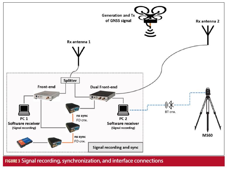
The UAVlite signals as well as the signals in space (SIS) are captured by two geodetic GNSS antennas. The antennas are separated by a distance of approximately 40 meters. On the receiver side we are using multi-GNSS software receiver front-ends (FE) (see Manufacturers and Additional Resources). The setup for signal recording is sketched in Figure 3. The Rx antenna 1 is connected via an RF-splitter to the Single-FE (S-FE) and the first RF input of the Dual-FE (D-FE1), with cable length of approximately 10 meters. The Rx antenna 2 is connected to the second RF input of the Dual-FE (D-FE2), with cable length of approximately 50 meters. Both FE are connected to a PC for IF sample recording. PC1 records the IF sample stream of the S-FE and PC2 records both IF sample streams of the D-FE. Both FE record with a sampling rate of 200 MHz/s and 2 bits per sample (real valued IF sampling). The recorded signals of the D-FE are clock and time synchronized and can be used in post processing without additional clock synchronization effort. However, comparing the record of the S-FE with the record of the D-FE2 is only possible if the FE clocks are synchronized. The clock synchronization is described below. Also a time offset synchronization is needed. This is currently done by tracking the GPS SIS and determining the PC time offsets to the GPS time.
The transmitted UAV signal is without secondary code and therefore without any long range timing information. To overcome this lack of information, the Hardsync option in the MuSNAT is used for the pseudorange determination. In Hardsync mode, the code ambiguity is resolved under the assumption of a vanishing measured receiver clock error, a vanishing satellite clock error, and with geometric distance much smaller than the code period. This procedure can be used and is uncritical as we are only interested in the pseudorange differences and therefore all constant time offsets are canceled, as mentioned earlier.
Front-end Clock Synchronization
The clock synchronization between the GNSS receivers is another crucial element in this testbed because of the absence of an atomic clock in the UAV transmitter. The simplest means of synchronization is to use a coaxial cable in between the two receivers, but a clock synchronization between two buildings (and in a later phase of the project between multiple buildings of the University campus) clearly needs a long distance synchronization tool. We have chosen the so-called “White Rabbit Project” for this task. An additional advantage of such synchronization devices is, that they support clock synchronization in addition to time synchronization, which provides us a GNSS synchronization with all devices of our setup.
White Rabbit (WR) is a collaborative project of CERN, GSI Helmholtz Centre for Heavy Ion Research, and other partners from universities and industry. The hardware design as well as the source code are publicly available (Additional Resources). Our version is a COTS product of the Spanish company Seven Solutions S.L. with the name WR-LEN. WR-LEN provides sub-nanosecond accuracy via fiber connections over 80 kilometers of length. Thus this approach will allow us to later use multiple ground stations distributed even kilometers away from each other.
In our setup (see Figure 3) we used three WR-LENs. They were connected in a daisy chain (master, slave No. 1, and slave No. 2), in which the master was driven by a GNSS receiver with the PPS and 10 megahertz clock signal. The front-ends were connected with slave No. 1 and No. 2, respectively. One of the front-ends has two phase-aligned inputs, which gives us the possibility to compare the test results with the WR-synchronization, i.e., a “perfect” synchronization. The longest fiber connection we used was 250 meters long with most of the coils still on the cable reel.
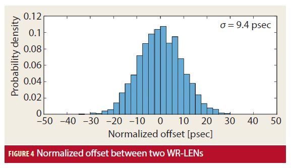
The accuracy of the WR-LENs were measured in our laboratory. Therefore, the virtual bench with a customized application program was used to measure the time difference between the clocks of the WR-LENs. Figure 4 shows the histogram of two WR-LENs over a measurement time of approximately 36 minutes. The standard deviation of the clock jitter was 9.4 picoseconds. During the flight tests, we observed deviation between 14 and 16.6 picoseconds. This can perhaps be explained by stronger temperature conditions and/or a higher uncertainty of the measurement setup, but the results are still in the expected range. The brochure of the WR-LEN of Seven Solutions is showing similar results with the same deviation and a maximum time interval error (MTIE) of ±45 picoseconds. The WR concept demonstrated even better results with deviations of five to six picoseconds, but also, that there is a temperature effect on these systems of approximately four picoseconds per one degree Celsius. (See Additional Resources for both of these systems.)
Positioning and Ranging Verification
For positioning and ranging verification, a multistation is used (again, see Additional Resources). The multistation operates with an electronic distance measurement (EDM) unit to compute the slope distance from the device to a reflector (prism). The distance is calculated by comparing the electromagnetic wave transmitted from the instrument to the one that is reflected back to the instrument. For the position accuracy specification, the distance to a fixed target was measured for five minutes. The distance between the multistation and the target was 20.127 meters. In the five minutes, a standard deviation of the measured distance of 93 μm could be observed. A distance bias was not determined, as constant distance offsets are canceled during the delta range processing. The multistation is able to acquire a target (reflector) up to 450 meters away and track it in locking mode up to 250 meters while the target is moving. This characteristic is very important as we want to track the UAV when it is flying. The maximum speed that the lock mode supports is 14 m/s. As mentioned before, the idea of using the multistation is to measure accurately the position of the three antennas with respect to their phase center: Rx antenna 1 and Rx antenna 2, which stay on ground and have a static position; and the Tx antenna, which is mounted on the UAV and is tracked during the flight (see Figure 5). Hence, a complete description of the geometry between the three phase centers is possible at all times. This allows the computation of the real distances (ρ1, ρ2) between the Rx antennas and the Tx antenna.
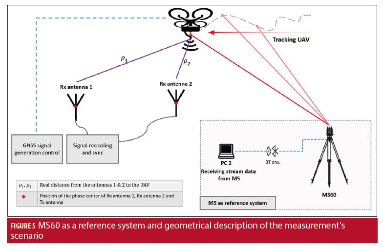
For Rx antenna 1 and Rx antenna 2, single point measurements are done with the multistation, as they are fixed on the ground and their position is static. On the contrary, with the Tx antenna, the data measured by the multistation is streamed in real time to PC2 through a Bluetooth connection at 20 hertz. The 20 hertz is the maximum measurement rate. In our test we observed a mean rate of 15 ± 5 Hz. The streamed data is stamped with the time given by the multistation. The time of PC2 and the multistation is synchronized at the beginning in the range of milliseconds, thus allowing a direct comparison with the signal recorded on PC2 as they share the same timestamp. Among the data that is streamed, one can find: Northing [m], Easting [m], Elevation [m], horizontal angle [rad], vertical angle [rad], slope distance [m], and time stamp [hh:mm:ss.ss].
Another point worth mentioning is the multistation setup, which is performed prior to the measurements, in which the computation of the orientation of the instrument is performed by using the known position of three geodetic pillars. One pillar, in which the multistation was installed, and the remaining two to use as multiple back sights. This step allows for having the coordinates of the targets in a global reference system instead of the instrument’s local coordinate system.
UAV
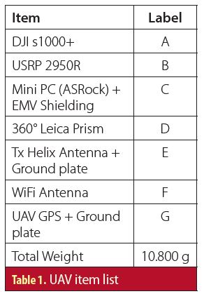
For our UAV, we chose a professional octocopter drone. The octocopter has a weight of 4.9 kg and is able to carry a payload of approximately 6 kg (including the batteries). The air time fully equipped is 12 minutes. The drone has IMU, GPS, and compass modules on board for stabilization. To shield the UAV electronics (especially the GPS antenna) from RF interference, an aluminum ground plate must to be installed between the UAV GPS antenna and at the Tx antenna. It was also necessary to cover the housing of the mini PC with EMV paint to ensure the UAV GPS reception. The housing of the mini PC as well as the mounts for the USRP, prism, Tx antenna, and battery were self-designed and 3D printed. A list with the main parts is shown in Table 1. The labels refer to the corresponding parts in Figure 6.
Results
Full results and more will be published in Part 2 in the November/December issue of Inside GNSS. Additionally, a full version of the article will be published online at insidegnss.com.
Manufacturers
The software defined radio reconfigurable device used in the Pseudolite (Transmitter) section is a SDR USRP 2950R from National Instruments, Austin, Texas. Also, the virtual bench with a customized application program that was used to measure the time difference between the clocks of the WR-LENs was the VB-8054 from National Instruments.
In Receiver System where the authors state that the UAVlite signals as well as the signals in space (SIS) are captured, they are done so with two Trimble Zephyr 2 Geodetic antennas from Trimble, Sunnyvale, CA. Also in the Receiver Section, IFEN multi-GNSS software receiver front-ends (FE) from IFEN GmbH, Poing, Germany, are used; the SX3 Dual-RF-FE (D-FE) and the SX3 Single-RF-FE (S-FE).
In Positioning and Range Verification, the authors are referring specifically to the MultiStation MS60 from Leica Geosystems, Heerbrugg, Switzerland.
The GNSS receiver used in the Front-end Clock Synchronization section is the PolaRx4TR from Septentrio, Leuven, Belgium and Torrance, CA.
The drone referenced in the UAV section is the DJI Spreading Wings S1000+ Octocopter from DJI, Shenzhen, China.
Acknowledgments and Disclaimer
Acknowledgement should go to Gerhard Kestel, Stephan Ullrich, and Mathias Philips-Blum for their support during the measurement campaigns and their work setting up the testbed system. The project is self-funded by the Institute of Space Technology and Space Applications of the “Universität der Bundeswehr München.” The setup and the gained knowledge are and will be used for the DLR projects SatNavAuth (FKZ: 50 NA 1703) and NeedForPRS (FKZ: 50 NP 1708).
Additional Resources
[1] IFEN, “SX3 GNSS Software Receiver,” http://www.ifen.com/products/sx3-gnss-software-receiver.html, 2017
[2] ISTA, “Multi Sensor Navigation Analysis Tool (MuSNAT),” https://www.unibw.de/lrt9/lrt-9.2/software-packages/musnat/view, 2018
[3] Leica Geosystems, “Leica Nova MS60 – The World’s First Self-Learning MultiStation,” http://leica-geosystems.com/products/total-stations/multistation/leica-nova-ms60, 2017
[4] Lipinski, M., “White Rabbit – Ethernet-based Solution for Sub-Ns Synchronization and Deterministic, Reliable Data Delivery,” Presentation (Tutorial), IEEE Plenary Meeting, Genève, July 2013 (http://www.ieee802.org/802_tutorials/2013-07/WR_Tutorial_IEEE.pdf)
[5] Maier, D. S., Kraus, T., Blum, R., Philips-Blum, M., and Pany, T., “Feasibility Study of Using UAVs as GNSS Satellites,” Proceedings of the 30th International Technical Meeting of the Satellite Division of The Institute of Navigation (ION GNSS+ 2017), Portland, OR, September 2017
[6] Maier, D. S., Frankl, K., and Pany, T., “ The GNSS-Transceiver: Using Vector-Tracking Approach to Convert a GNSS Receiver to a Simulator; Implementation and Verification for Signal Authentication,” Proceedings of the 31st International Technical Meeting of the Satellite Division of The Institute of Navigation (ION GNSS+ 2018), Miami, FL, September 2018
[7] National Instruments Corporation, “SPECIFICATIONS USRP-2950,” http://www.ni.com/pdf/manuals/374194d.pdf, 2017
[8] Project on the Open Hardware Repository platform “White Rabbit Project,” https://www.ohwr.org/projects/white-rabbit
[9] Seven Solutions, “WHITE RABBIT LEN – WR-LEN,” brochure, http://sevensols.com/index.php/download/brochure-white-rabbit-len/?wpdmdl=992
Authors
Daniel Simon Maier has a professional training as a technical draftsman and received a bachelor in Physics in 2015 and a master in Applied and Engineering Physics in 2017 from the Technical University of Munich (TUM), Germany. Since 2017 he has been a research associate at the Institute of Space Technology and Space Applications of the “Universität der Bundeswehr München.” His current research interests include GNSS signal generation, signal authentication, and signal performance analysis.
Thomas Kraus graduated with a M.Sc. in Electrical Engineering from the University of Darmstadt, Germany. In 2008, he joined the Institute of Space Technology and Space Applications of the “Universität der Bundeswehr München.” He’s been working as a research associate on several projects of the German Space Agency (DLR) and European Space Agency (ESA-ESTEC). His main research focus is on future receiver design offering a superior detection and mitigation capability of intentional and unintentional interferences.
Daniela Elizabeth Sánchez Morales studied Telematics Engineering at Instituto Tecnológico Autónomo de México (ITAM) in Mexico City. She also holds a Masters degree in satellite applications engineering from the Technical University Munich (TUM). She has been a research associate at the Institute of Space Technology and Space Applications (ISTA) since 2017. Her main research area is sensor fusion. Her current research focuses on LiDAR, sensor fusion between LiDAR and GNSS/INS, and relative and absolute navigation algorithms particularly for terrestrial applications.
Ronny Blum received his Masters in Physics from the University of Basel, Switzerland. He then worked at Würth Elektronik in the field of signal transmission and later on at the Forest Research Institute in Freiburg im Breisgau in the field of GNSS reception within the forest. In 2017 he joined the University of Federal Armed Forces Munich, where he is working in the field of GNSS software receiver.
Prof. Thomas Pany is with the Universität der Bundeswehr München at the faculty of aerospace engineering where he teaches satellite navigation. His research includes all aspects of navigation ranging from deep space navigation to new algorithms and assembly code optimization. Currently he focuses on GNSS signal processing for Galileo second generation, GNSS receiver design, and GNSS/INS/LiDAR/camera fusion. To support this activities, he is developing a modular GNSS test bed for advanced navigation research. Previously he worked for IFEN GmbH and IGASPIN GmbH and is the architect of the ipexSR and SX3 software receiver. He has around 200 publications including patents and one monography.
Em. Univ.-Prof. Dr.-Ing. habil. Dr. h.c. Guenter W. Hein is Professor Emeritus of Excellence at the University FAF Munich. He was ESA Head of EGNOS & GNSS Evolution Programme Dept. between 2008 and 2014, in charge of development of the 2nd generation of EGNOS and Galileo. Prof. Hein is still organising the ESA/JRC International Summerschool on GNSS. He is the founder of the annual Munich Satellite Navigation Summit. Prof. Hein has more than 300 scientific and technical papers published, carried out more than 200 research projects and educated more than 70 Ph. D.´s. He received 2002 the prestigious Johannes Kepler Award for “sustained and significant contributions to satellite navigation” of the US Institute of Navigation, the highest worldwide award in navigation given only to one individual each year. G. Hein became 2011 a Fellow of the US ION. The Technical University of Prague honoured his achievements in satellite navigation with a Doctor honoris causa in Jan. 2013. He is a member of the Executive Board of Munich Aerospace since 2016.


