In-flight refueling requires sustained minimal separation between paired aircraft with little room for error. In or near combat zones, wide-area GPS-denial or spoofing means that an GPS-independent system must be available. Regardless of the selected sensor package, a common set of properties must be satisfied to facilitate mid-air docking: a high degree of accuracy, precision, and integrity.
At 0400 hours, a manned surveillance aircraft has been in the air for several hours. It approaches a refueling tanker, closing in for dock. Onboard the unmanned tanker, a computer automates the boom, maneuvering it to dock with the receiver—the trailing aircraft acquiring fuel from the tanker. Now fully refueled, the surveillance aircraft remains airborne and vigilant.
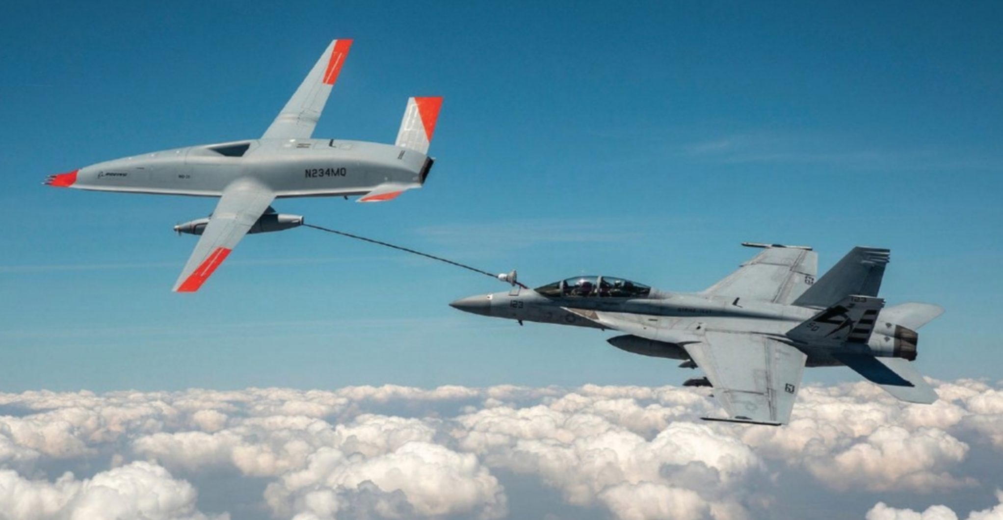
This scenario may be closer to reality than one may think. In June 2021, an unmanned MQ-25 Stingray successfully refueled a Navy Super Hornet. As simple as the scenario might seem, there are several factors required for successful automation of aerial refueling (AAR).
In the June Navy Stringray scenario, the autonomous MQ-25 tanker was equipped with a U.S. Navy drogue. This drogue is essentially a basket extending from the tanker’s rear via a fuel hose. The F/A 18 Super Hornet, a manned receiver, was responsible for approaching this basket and maneuvering its rigidly mounted fuel probe into the tanker’s trailing drogue. Once docked, fuel transfer commenced. The MQ-25 is capable of flying via a GNSS-based flight path and generally holds a stable path while a receiver is attempting to dock with its drogue.
In-flight refueling requires sustained, minimal separation between paired aircraft with little room for error. In prior demonstrations, this has been achieved using differential GPS, but many different sensor packages could be employed with varying tradeoffs. Regardless of the selected sensor package, a common set of properties must be satisfied to facilitate midair docking: a high degree of accuracy, precision, and integrity.
Our research focuses on a tanker-centric stereo vision system for determining relative navigation between the tanker and receiver. Adding a vision-based system introduces several advantages. A second sensing system in addition to GNSS can be used for ensuring integrity. Fusing the GNSS and vision-based inputs may lead to improved performance over either individual system. Since refueling occurs near combat zones, if wide-area GPS-denial or spoofing occurs, employing an independent vision-based system allows refueling operations to continue.
A visual relative navigation approach also has some distinct advantages over a GNSS-based approach. To obtain cm-level accuracy or better, differential GNSS-based methods require constant communication and information sharing between the tanker and receiver. This implies modification of the receiver to enable AAR based on GNSS. A stereo vision technique modifies the tanker only; we assume no modification to the receivers. While the number of possible receiver aircraft is very large, the number of tanker aircraft is comparatively few. Therefore, the stereo vision approach may be easier to deploy and lower-cost to maintain than a GNSS-based technique. In addition, modern tankers are often already equipped with a stereo vision system to assist the human refueler, minimizing the quantity of new external equipment required for this approach.
Despite these advantages, the refueling receptacle on a receiver aircraft is only a few centimeters in diameter but approximately 25 meters from the stereo cameras, requiring extremely high relative navigation accuracy to guide the boom. Additionally, we desire our approach to be completely independent of any GNSS system, adding redundancy and resiliency to the refueling system. Because refueling is a dynamic situation, any algorithm to automate mid-air docking must run in real-time.
Designing a system to meet these constraints requires innovations in several areas, including computer vision, machine learning, and parallel computing. In addition, verifying the system performance presents a unique challenge. Conducting real-world tests involving actual tanker and receiver air- craft is costly and time-prohibitive. As a starting point, virtual environments can be used to accurately simulate and verify the algorithm, as the truth data is known. Beyond virtual-only simulations, smaller scale real-world tests are also possible; however, knowing the truth data becomes more challenging. As stated, any automated refueling algorithm must be accurate within a few centimeters, requiring a truth system with millimeter-level accuracy.
Approach
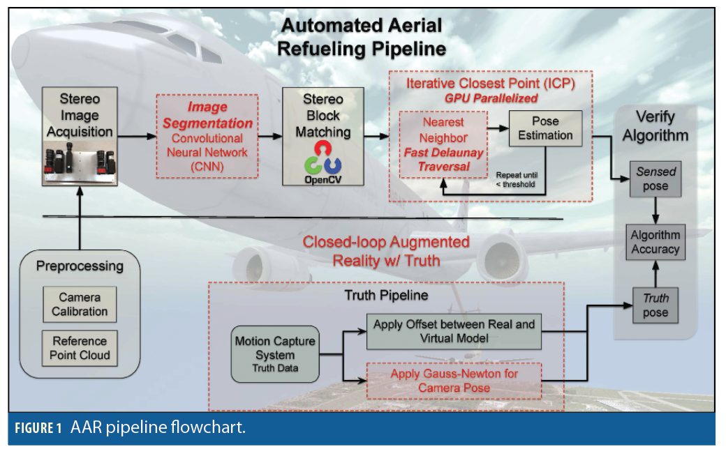
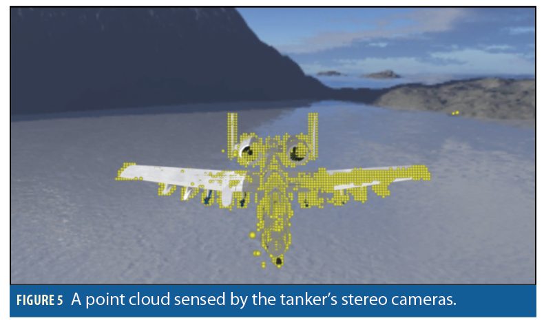
Our pipeline for estimating the receiver’s pose (position and attitude) relative to the tanker while meeting these constraints, is shown in Figure 1. The pipeline consists of several components, some of which are standard image-processing steps (black solid lines), and some that have been customized to adapt to various aspects of AAR (red dashed lines). Before flight, preprocessing steps, including calibrating the stereo camera system and generating the reference point cloud, are performed. The first step of the algorithm is to acquire a pair of stereo images from 4k cameras in gray-scale. Stereo block matching (SBM) can be used to match similar pixels in the left and right images. The difference between the matches, or disparity, is used to reproject these 2D points into 3D space, forming a sensed point cloud of the receiver. (Figure 5 shows a sensed point cloud from an approaching receiver aircraft.) This sensed point cloud intrinsically encodes the pose of the receiver relative to the stereo camera system.
Optionally, the captured images can be fed into a convolutional neural network (CNN) trained to detect the cropping area of the receiver. This procedure allows the next step, SBM, to only evaluate pixels belonging to the aircraft; in our experiments this enhancement provides an 11x decrease in SBM computation when using 4k cameras.
However, one cannot directly extract the receiver’s relative pose without further computations. To extract the relative pose from the sensed points, we employ point registration, specifically Iterative Closest Point (ICP). This process registers a reference point cloud onto the sensed point cloud which computes the relative rotation and translation between the receiver and stereo cameras: [R3x3. t3x1].
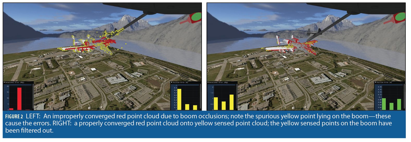
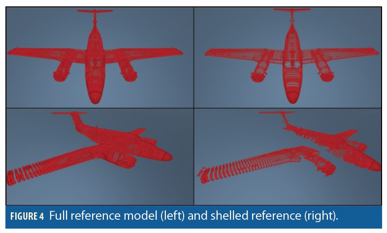
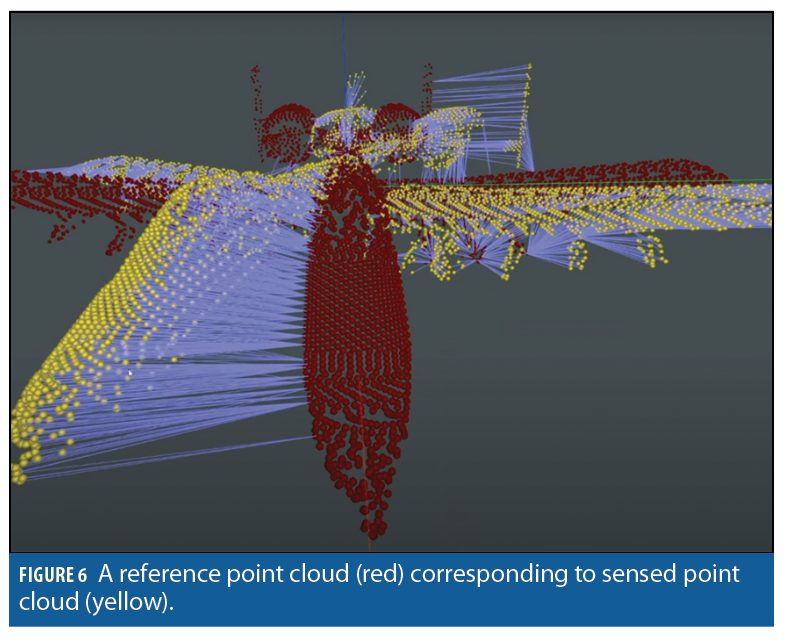
The reference point cloud is generated a priori from the known geometry of the receiver’s airframe as shown in Figure 4. To automate selection of the correct reference point cloud, we employ CNNs to classify an approaching receiver and select its corresponding reference point cloud for the point registration process. Figure 6 shows a red reference point cloud registered onto a yellow sensed point cloud. Similarly, the right of Figure 2 shows a properly registered reference model lying on top of a sensed yellow point cloud. In turn, the sensed yellow point cloud is lying upon the surface of the receiver’s actual airframe indicating a good reprojection of sensed 3D points. When all three align, our algorithm is functioning as designed. In the case of a simulation or virtual world, we know the pose of the actual receiver, so we can directly quantify the errors resulting from the stereo sensing and point registration.
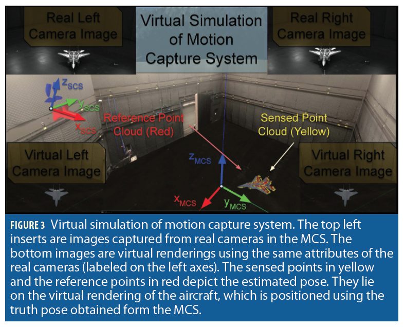
To verify the algorithm produces an acceptable output, the algorithm’s sensed pose is compared with the truth pose. To collect accurate truth data, we have developed a closed-loop augmented reality environment. First, a mo tion capture system (MCS) shown in Figure 3 provides the pose of the receiver. This pose is with reference to the MCS, so the virtual representation requires an offset to line up with the truth. This offset is determined via a novel use of the Gauss-Newton optimization technique.
Preprocessing Calibration
Possibly the most critical issue for obtaining accurate pose estimates is ob taining a precise intrinsic and extrinsic camera calibration. The intrinsic calibration matches the mathematical pinhole model to real camera attributes, accounting for properties such as focal length, lens distortion, optical center, and image resolution. The extrinsic calibration enables us to precisely determine the stereo camera baseline (horizontal distance between the cameras) and relative orientation between the left and right cameras. Once both the intrinsic and extrinsic parameters are known, we can un-distort and rectify image pairs and re-project matched features found in both the left and right images into 3D points. These 3D points form the yellow sensed point cloud shown in Figure 3. Note that performing calibration is a well-studied field and we utilize algorithms already implemented in OpenCV.
Reference Point Clouds
To estimate pose using a sensed point cloud, a reference point cloud of the receiver must be present to align the sensed point cloud with. Because we assume the type of aircraft being refueled is known, we assume a point cloud of the receiver can be created a-priori. In addition, because the receiver will essentially be observed from one perspective—above and in front of the receiver—we can reduce the reference model to include only points which can be seen from the refueling point of view. The result is a shelled reference model. In Figure 4 the full set of points is shown next to the shelled reference model. As seen in the top pairs, the point clouds look very similar. However, in the bottom images, several points located on the side of the aircraft appear in the left image but not the right image. From the point of view of the tanker, these points would not be detected by the stereo cameras. Removing them from the model has the advantage of improving accuracy as well as increasing the computation speed, as these points are not considered during the model registration steps in ICP.
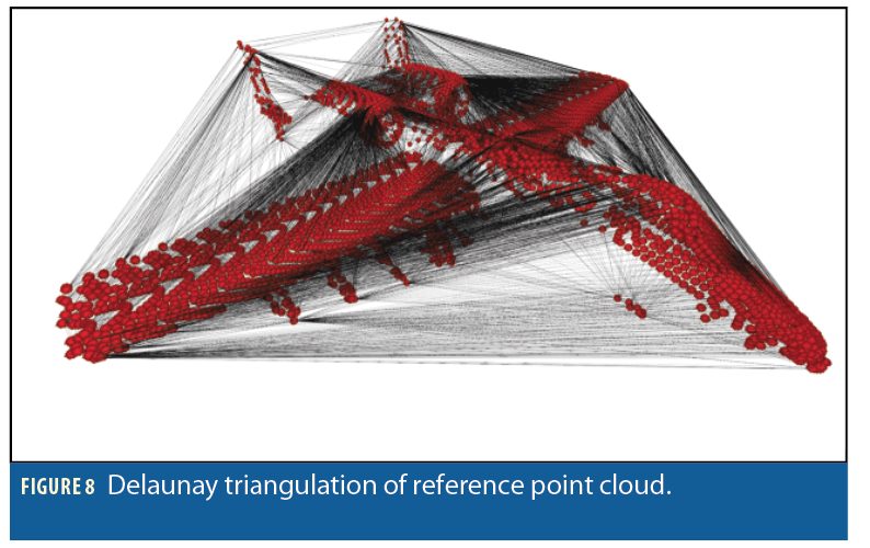
To further optimize computation time when performing ICP, the shelled reference model is further processed in two ways. First, a k-d tree typically is made that allows for searches of the data in approximate logarithmic time, O(log n) when no information about the aircraft pose is known. Second, we create a Delaunay triangulation of the point enabling us to run the nearest neighbor queries of ICP in an amortized constant time of approximately O(1).
Stereo Image Acquisition
When attempting to refuel, the first step in our AAR pipeline is to capture a pair of stereo images. There are two items of particular import. First, the timing of the camera capture is extremely important. Both cameras need to capture the image at exactly the same time or else the sensed point cloud will have significant errors in the point cloud. Furthermore, when evaluating the performance of the AAR pipeline, the capture time and the timestamps for the truth data must be precisely aligned. Second, the resolution of the captured images significantly affects the final accuracy of the system. For the purposes of AAR, we began our experiments with 1280×960 resolutions, but we eventually transitioned to 4k cameras to achieve the accuracy required at the desired standoff distances. This increase in pixels, however, leads to a significant increase in computational requirements of the SBM step. Our approach to mitigating this issue is described under Image Segmentation.
Stereo Block Matching
After images have been acquired, pose estimation based on that imagery is the key to accurate relative navigation. Many approaches to estimating the pose of known objects use features from the image and map them to the same features lying on the geometry’s surface. These techniques require features on the object being tracked be visible in all imaging conditions (lighting, shadows, glint, etc.).
In addition, the fewer the number of features, the more accurately the features must be found in each image, leading to a sub-pixel accuracy requirement in many scenarios.
Alternatively, we chose to create a dense point cloud that generates thou- sands of points in 3d space (generally one point per pixel on the receiver aircraft), thereby averting sensitivity to improper matches. We found this approach to be more applicable to AAR for two reasons: (1) we assume no beacons exist nor can they be added to any aircraft, making the unique feature identification problem very difficult and (2) we believe that achieving accuracy through the use of 1000s of features is more robust to mis-identification and image acquisition conditions than techniques based on fewer features. The creation of a dense point cloud is a well-studied problem and is solved utilizing SBM techniques found in the open source computer vision library OpenCV.
SBM employs two cameras with known separation geometry where each camera captures the scene from a slightly different perspective. A feature in one image maps to an epipolar line in the other image. From these corresponding pair-wise matches, a disparity map is generated. The disparity map, in conjunc tion with the calibration parameters, can be used to reproject each pixel to a 3D location. This produces a 3D point cloud for each image pair. In this work each image pair produces about 40,000 points. Unfortunately, this many points makes the next step take too much computation time. Therefore, we chose to subsample the data to 5,000–6,000 points as this value appears to balance accuracy and computation time. These (Figure 5) sensed 3D points now serve as input to the pose estimation/registration algorithms.
Iterative Closest Point
In our algorithm, we have two point clouds to consider. The first is the yellow sensed point cloud generated from our stereo vision camera; this point cloud will be somewhat noisy as it is the output of our SBM process, see Figure 5. The second point cloud is the red reference model containing the ideal geometry of the receiver aircraft. This reference model’s point distribution is chosen based on the stereo camera resolution and the expected receiver distance from the camera at the docking location.
Importantly, the sensed point cloud intrinsically encodes the relative pose between the stereo camera and the receiver. To extract this relative pose from the sensed point cloud, we estimate the rigid transformation (rotation and transla tion) that best aligns the reference model onto the noisy, spurious sensed model, i.e., transform the red points onto yellow points as shown in Figure 2. Because we know the reference model is accurate, if we find this transformation we then arrive at a relative pose between the camera and receiver. Because we know the geometry of the reference model, this also estimates the specific location of the docking receptacle for AAR.
To estimate the aforementioned registration, we use a variant of the ICP algorithm. ICP works by first finding, for every point in the sensed point cloud, its “nearest neighbor” in the reference point cloud. An example correspondence is shown in Figure 6. After this, a summed outer product matrix is constructed from the outer product of each nearest neighbor pair. Decomposing the outer product matrix into orthonormal rotation matrices via methods such as singular value decomposition (SVD) yield a rigid rotation representing the change in orientation between the two point clouds. The vector between each cloud’s center of mass yields a translation vector; thus, the rotation and translation produce the desired transform. After applying this rotation and translation, the nearest neighbor matches may have changed, so the process repeats. At the end of this iterative process, the rotation and translation that best maps the sensed point cloud onto the reference point cloud is output as the estimated pose of receiver.
Real-Time Execution
Because of the need for an AAR algorithm to run in real-time, the standard algorithms described above do not work “out of the box”. We have added a block between the image acquisition and SBM blocks, and modified the ICP algorithm to enable real-time performance.
Image Segmentation via CNN
When performing SBM, the expected error at a given range can be calculated using

where ez is the depth error, z is the depth, b is the baseline, f is the focal length (in pixels), and εd is the matching error in pixels (disparity values, assumed to be one). While the field of view of the sensors, the depth, and the baseline are all fixed by the AAR scenario, we can increase the focal length f by increasing the number of pixels within the same field of view of the camera. AAR’s long ranges and need for high accuracy require a relatively high resolution.
The downside of higher resolution images is the computation time required for SBM to generate the disparity map. However, a depth map is not required for everything in the capture images, just the receiver. At a distance of 25 meters, the receiver will generally not fill the entire image frame, causing SBM to waste significant computational resources. Therefore, we designed a method to efficiently find the receiver within the broader image and limit SBM to operate on that portion of the image.
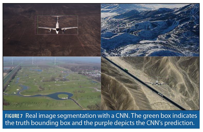
To segment the image and reduce computation time required for SBM, a CNN was trained to output the bounding coordinates for the receiver. Generating images from actual refueling approaches is costly, and truth data is difficult to obtain. Therefore, the CNN was trained on images of real landscape scenery with a virtual aircraft rendered at a random but AAR-friendly pose. Once trained, we were able utilize the CNN model on real images without adjustments. Figure 7 shows the results of running a real image through the CNN. The green lines represent the truth bounding box while the purple lines denote the CNN’s prediction. This technique led to an 11x decrease in SBM processing time for 4k images.
Parallel ICP on GPU
Aside from SBM, ICP also presents a barrier to real-time execution. To address this issue, we implemented a novel variant of the ICP algorithm using Nvidia’s CUDA to enable a highly parallelized implementation on a graphics processing unit (GPU). ICP’s nearest neighbor (NN) matching step is, by far the slowest step, but also inherently parallel. This step iterates over the entire sensed yellow point cloud, and for each point, finds for the closest red point residing in the red reference point cloud. Figure 6 shows these matched correspondences as the purple lines. Each of these NN searches can run in parallel on their own thread. By choosing a GPU with more Stream Processor Units than sensed yellow points, we effectively reduce a naive O(n2) algorithm to O(n), at least with respect to time complexity. Beyond NN matching, the subsequent step, Rotation/Translation estimation, requires a summation of displacements from each pair of points, requiring all computation between points to be completed before decomposing the outer product matrix. Therefore, we leverage the parallel reduction: each task is split into sub-tasks with the ultimate goal of reducing all data into a single value. Executing ICP on a GPU reduced computation time by roughly 95x over serial versions. Although a vast improvement of almost 2 orders of magnitude, ICP was still not fast enough to run in real time while registering point sets on the order of approximately 10, 000 points. To overcome this hurdle we developed a novel Delaunay Triangulation algorithm.
Delaunay Triangulation
While parallelizing the ICP algorithm led to significant reductions in run time, our AAR algorithm required we register our sensed and reference point clouds (on the order of 10, 000 points) in less than 20 msec. Analyzing the ICP algorithm, we found that ICP’s nearest-neighbor search consumed the vast majority (>97%) of computation time. Fortunately, we were able to develop a novel algorithm that dramatically decreased the nearest neighbor search—amortized over time, this algorithm produced an O(1) time complexity for any given NN query.
Traditional methods use tree-based approach such as, a k-d tree which partitions the data along the median value of each sequential axis. A CNN query using a k-d tree is on average is O(log n) with the worst case being O(kn(1−) (for 3D points, k is 3) for points in particularly poor locations.
We investigated an alternative correspondence search utilizing a Delaunay triangulation of the reference points. A Delaunay triangulation turns a set of points into a graph with a specific structure that is useful for finding nearest neighbors. The graph is connected such that if a query point is closer to a node in the graph than all of its neighbors, then that node is the nearest neighbor of the query point. Our Delaunay traversal algorithm walks along edges in the graph until there are no other points closer to the current candidate point. The main advantage to this approach is the ability to begin the search from any given point. In a k-d tree, searches must typically begin at the root node, leading to a best-case O(log n) run-time. In our Delaunay traversal, the search can begin from any arbitrary point. Because ICP is an iterative algorithm, we can start the NN search from the previous iteration’s nearest neighbor. In general, this cache-friendly approach leads to a very small number of neighbors traversed per iteration.
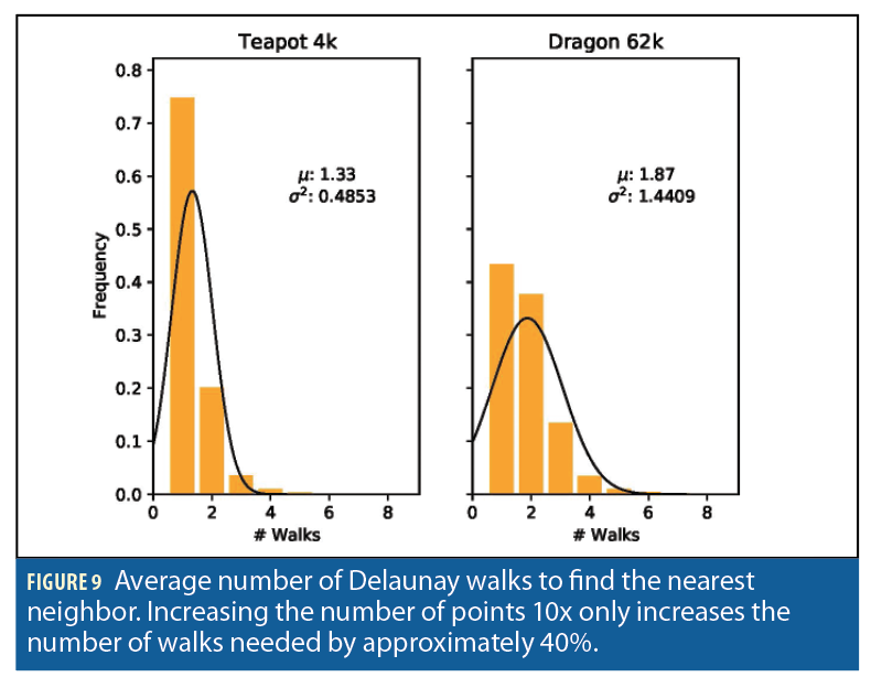
In fact, our experiments have shown that on average, only 1-2 walks are required for each subsequent ICP iteration (Figure 9). Additionally, we have seen this performance regardless of the size of the data set. Thus, our Delaunay traversal approach reduces the O(log n) time complexity to an amortized O(1) time complexity. Evidence of this behavior is seen when analyzing the average num ber of walks taken for point clouds of various sizes. In Figure 9, a 3D teapot model with ~4k points is shown to have taken 1.33 walks on average to find the nearest neighbor. In comparison, a 3D dragon model with ~62k points took 1.87 walks on average. Using this approach together with the parallelized ICP, we have been able to complete 30 iterations of the ICP algorithm in around 18ms for point clouds with ~10k point, making ICP computation a real-time possibility for AAR.
Low-cost Verification of AAR algorithms
As new algorithms are being developed and refined for AAR, the problem of verifying the performance of these algorithms becomes essential. Unfortunately, real flight tests are expensive, time-intensive, and may not provide perfect truth data needed for accuracy testing (differential GPS gives centimeter-level accuracy, but truth should really be closer to millimeter-level or better). Therefore, we have adopted two approaches to verifying our algorithms’ performance.
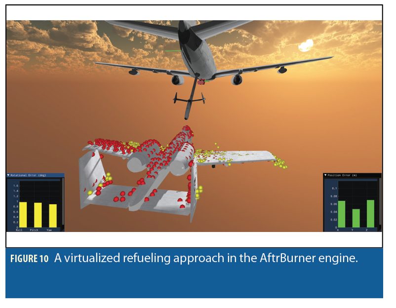
First, we have constructed a virtual refueling scenario using the AftrBurner (3D visualization/game) engine to test our vision pipeline. A geometrically accurate refueling tanker is placed in the 3D virtual world with a pair of stereo cameras attached to the rear of the tanker. A receiver aircraft initiates a refueling approach and flies towards the tanker as shown in Figure 10. The virtualized stereo cameras capture image pairs and feed them to the AAR pipeline (Figure 1) to produce estimated poses for the receiver aircraft. This vir tual environment is convenient as it provides absolute truth and the calibration, timing, and other issues are easy to resolve.
Second, we desired a test setup that utilized real stereo sensors so that the processing performance can be representative of real-world scenarios. In addition, we needed the ability to test closed-loop performance when movement of the boom (which will occlude key parts of the image) is added to the system. Therefore, we developed an augmented reality system.
Augmented Reality Setup
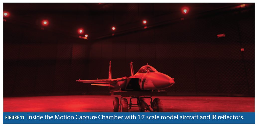
For our augmented reality framework, we utilized a motion capture chamber (MCS) that is approximately 15 × 20 meters in size (Figure 11). The motion capture system, through the use of 50 infrared cameras placed in the chamber, can track the position of markers (infrared reflective balls) anywhere in the room to about 1mm accuracy at a rate of 75Hz. By attaching multiple markers to an object in a known configuration, accurate estimates of attitude are also returned.
To simulate AAR, we mounted a pair of 4K stereo cameras approximately 8 meters high in the room to simulate a view akin to a tanker observing an approaching receiver aircraft. A 1:7 scale realistic model of a receiver aircraft is placed in the chamber with markers attached, see Figure 11.
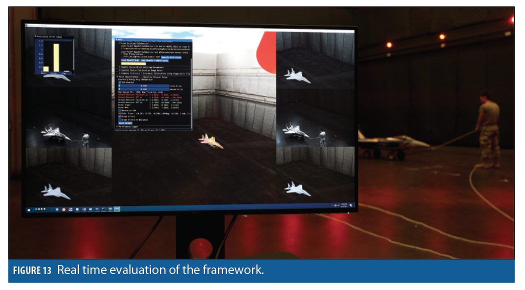
To conduct an approach in the MCS room, we physically pull the real-life 1:7 scale aircraft towards the stereo vision cameras (Figure 13: Red Box). This simulates a receiver approaching the tanker; the MCS is large enough that we can evaluate camera-receiver ranges of 10-25 meters—these ranges are ideal for testing the most crucial phase of AAR docking and refueling. We capture the receiver’s approach from two time-synchronized 4k cameras at 10Hz. We time-align and associate each captured image pair with the receiver’s absolute truth pose provided by the MCS. This data is then streamed in real-time to the Augmented Reality AftrBurner virtual world.
The physically acquired images (Figure 13: Blue Box) are fed into the aforementioned AAR vision pipeline, resulting in the yellow (sensed) dots that shown in Figure 13 in the yellow box. The pose obtained by the MCS is used to update the position of the virtual receiver aircraft in the Augmented Reality Virtual world. This is the gray virtual model that is somewhat hidden underneath the yellow points shown in Figure 13. Ideally, the sensed yellow points ought to lie perfectly on the skin of this virtual aircraft (the gray textured aircraft). Such behavior indicates the MCS and the stereo cameras are aligned and share a consistent coordinate frame. The final 2 minutes of a YouTube video at https://youtu.be/Qw0W8qlOW8s&t=213s show this process unfolding in real-time. The final element is the red point cloud shown in the video and in Figure 13 in the yellow box. The red reference point cloud is registered onto the sensed yellow point cloud using our ICP variant. This computes the final pose sensed solely from the stereo cameras. This pose is compared against the pose from the mm-accurate MCS system to yield our total positional and rotational error. When the yellow point cloud lies nicely on the gray textured skin of the 1:7 scale receiver and the red points lie on the yellow points, the system is working well, typically with less than 3-5cm of error and less than 2 degrees of rotational error.
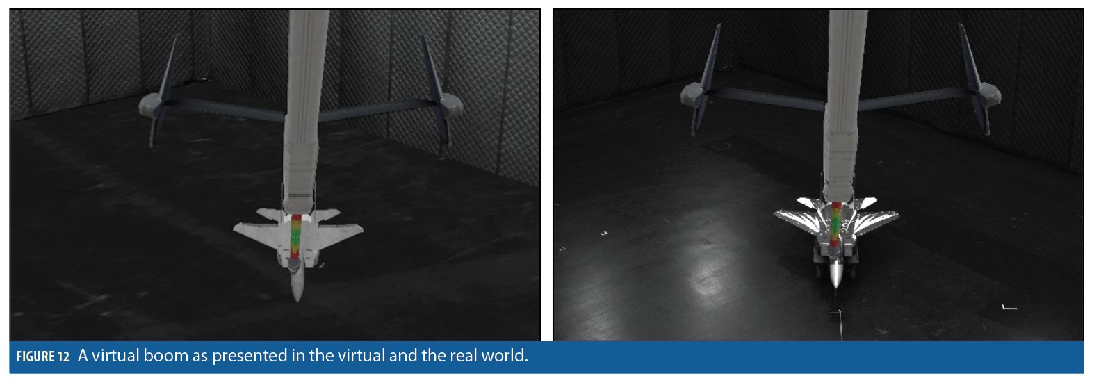
Beyond real-world tests, we can recreate the same path taken by the receiver inside the AftrBurner engine directly using the MCS truth data. This enables us to verify the performance of our virtual simulation engine as we can directly compare the performance on both real and virtual imagery. Perhaps more important, though, is the potential this system gives us for testing closed-loop performance. Rather than attempting to build a (large and unwieldy) 20m boom, we can virtually add the boom to real images captured to test performance of the system when the boom is being controlled using information from the visual processing pipeline. This gives rise to our augmented reality setup, as shown in Figure 12.
Gauss-Newton Optimization
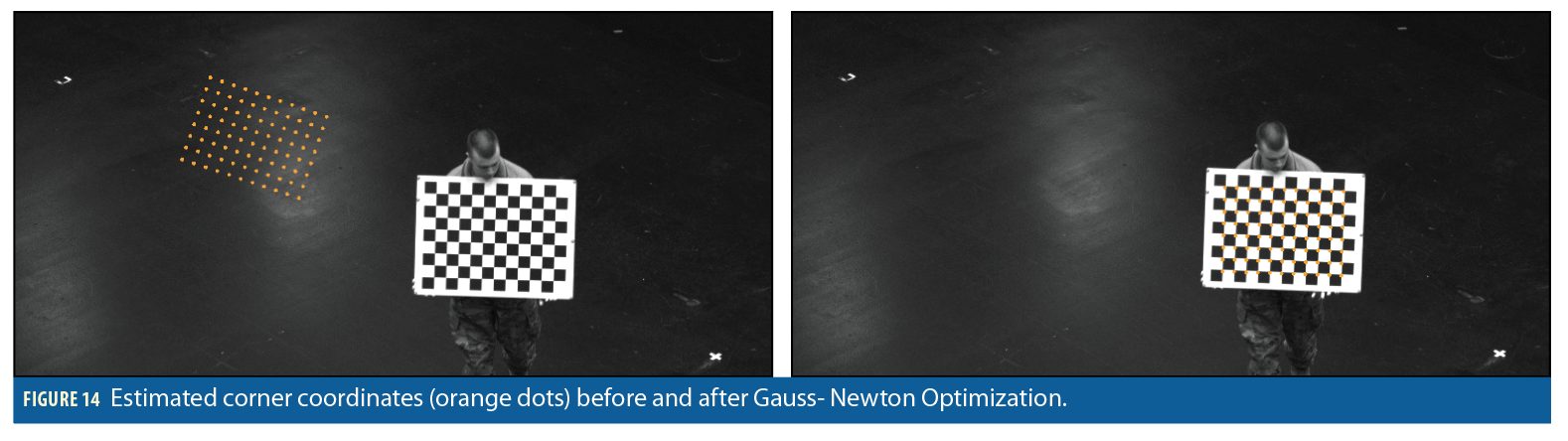
Key to evaluating the performance of AAR in the MCS room is the ability to transform pose estimates from the stereo cameras into MCS-based truth coordinates. To find this transform, we employed a Gauss-Newton optimization technique designed to generate an accurate pose of the real stereo cameras in the MCS coordinate frame. To find this transform, we created a checkerboard that had several IR markers on it, allowing it to be precisely localized within the MCS room.
The Gauss-Newton approach minimizes the errors between the measured image pixel coordinates of corners on a chessboard in captured images and where these corners are projected into the cameras based on the current transform from MCS to camera coordinates.
Before the optimization, the average distance between the estimated corner coordinates and the measured corner coordinates was about 280 pixels, see the left side of Figure 14. After optimization, the average offset was about 3 pixels, see the right side of Figure 14. The optimization allowed us to generate a good camera calibration for the real stereo cameras which minimizes reprojection errors and results in better convergence of the ICP algorithm.
With the transform output from the Gauss-Newton optimization, we achieved optimized alignment between the AftrBurner generated imagery using truth data and the real-world captured imagery. Without this excellent alignment, the augmented reality would suffer biases, with this excellent alignment, objects virtually projected into the real world are within a few mm of where we expect them to reside—quite useful when quantifying features that are occluded by the motion of the virtual boom projected on to the real-world 1:7 scale receiver.
Testing Augmented Reality Framework
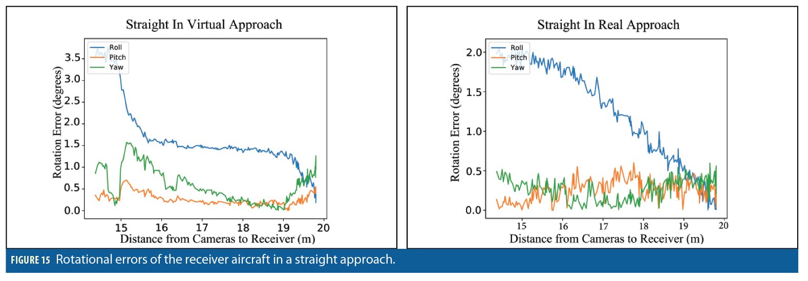
We conducted tests of the augmented reality environment with the physical 1:7 scale receiver approaching the stereo cameras in various patterns. For example, a straight-in approach involved pulling the physical 1:7 scale replica slowly towards the stereo cameras to simulate a real-world refueling approach (same approach shown in the aforementioned YouTube clip). The vision pipeline takes the imagery and produces pose estimates. The pose estimates are compared with the truth system poses to generate error statistics. These same truth values can also be used to generate virtual imagery, enabling the vision pipeline to produce pose estimates. In Figure 15, the error results for rotation estimates for both the virtual and real imagery are shown. Note that the overall magnitude and error characteristics of the two charts are very similar.
When analyzing several approaches collected via our augmented reality framework, we see a similar trend of pose errors between the real and virtual worlds. The virtual environment serves as an oracle: it predicts failure points of the real-world imagery and predicts accuracy within a small epsilon of the real-world measurements. When combined with the motion capture chamber and the truth data, the framework enables the approach collection to serve as an arbiter of truth and quantify any desired pose-estimation algorithm’s efficacy.
Virtual Boom
Another feature of our framework is the incorporation of virtual objects perspectively reprojected onto real-world imagery; ie, augmented reality. Figure 12 showcases a virtual refueling boom perspectively reprojected on to real imagery of the ap proaching 1:7 scale receiver model. This allows us to quantify the degradation caused by boom occlusion without requiring a physical boom to be installed.
Because our augmented reality is designed with ease of adaptability in mind, we can replace the virtual Air Force refueling boom with other refueling tips such as the Navy’s probe and drogue. This enhances our capability to test various vision algorithms on other flying platforms. It also enables us to generate truth data for real approaches and augment that truth data with perspective-correct occlusions. This truth data can then be reprocessed by any number of vision algorithms to quantify the efficacy of a suite of relative vision-based navigation algorithms.
Conclusion
We employ stereo vision cameras as an alternative to traditional GNSS-based relative positioning algorithms for automated aerial refuel ing. While many portions of the solution consist of relatively standard computer vision techniques, several novel modifications have been made specific to the AAR problem. Specifically, we have 1) employed CNNs to identify the air frame of an approaching receiver. Subsequently, another CNN 2) computes a smaller region of interest around the receiver dramatically reducing the number of pixels stereo block matching processes.
We have developed a 3) novel Delaunay-based nearest-neighbor algorithm that transforms a time-intensive search to an amortized constant time operation, enabling real-time ICP on tens of thousands of points. We further enhance this algorithm via 4) GPU parallelization. This real-time functionality gives rise to a closed-loop augmented reality system that 5) enables virtually reprojected objects, such as a refueling boom or refueling drogue, to dynamically respond to motion of a real aircraft.
Similarly, the augmented reality combined with the high-accuracy truth system lets us 6) generate truth data sets for occluded approaches. This lets us evaluate different vision algorithms against each other as we have mm-level accurate truth. Finally, the virtual simulation is high enough fidelity that it 7) serves as an oracle able to reliably predict the outcome of real-world approaches.
Conclusion
The authors thank Daniel Schreiter and the Air Force Research Laboratory Aerospace Systems (AFRL/RQ) directorate for their support.
Authors

James Anderson received his Master’s degree in computer engineering from Wright State University and is working on his Ph.D. there. His research work in collaboration with AFIT is on simulating and analyzing automated aerial refueling.

Captain Joel Miller commissioned in 2017 from University of Colorado, with a B.S. in electrical engineering. At AFIT he is working on his Master’s degree in computer engineering where his research is focused on automated aerial refueling.

Xiaoyang Wu is a graduate student in software engineering at the AFIT. He received his B.S. in computer science from Manhattan College. His research involves augmented reality in conjunction with image processing and real-time visualization.

Scott Nykl is an associate professor of computer science at AFIT. His areas of interest are real-time 3D computer graphics, computer vision, sensor fusion, parallel processing and Interactive virtual worlds. He has a Ph.D. in computer science from Ohio University.

Clark Taylor is assistant professor, computer engineering at AFIT. He has a Ph.D. in electrical and computer engineering from UC San Diego. He has published papers in video processing for UAVs, estimation theory, video comms and digital systems design.

Lt. Col. Warren Watkinson is Chief of the Sensor Plans and Advanced Programs Division at AFIT where he oversees advanced field and flight tests for air and space vehicles and a research portfolio of $1.5 billion. He has an M.S. in computer science from Ohio State University and does Ph.D. research at Colorado School of Mines.


