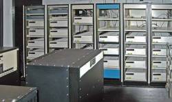
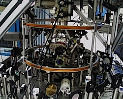
The European Space Agency (ESA) funded the development of a new GNSS/INS navigation system called DINGPOS to assess the potential utility of Galileo signals and current (L1) and new (L5) GPS signals for indoor positioning. The DINGPOS project also investigated new indoor positioning methods for pedestrians based on those signals and other sensors.
The European Space Agency (ESA) funded the development of a new GNSS/INS navigation system called DINGPOS to assess the potential utility of Galileo signals and current (L1) and new (L5) GPS signals for indoor positioning. The DINGPOS project also investigated new indoor positioning methods for pedestrians based on those signals and other sensors.
The integrated system may have applications as a pedestrian navigation system (PNS) for emergency forces and in the military domain. A key feature of the new system is its support of a coherent integration over several seconds of GNSS signal processing and the fusion of a multitude of positioning sensors.
The system incorporates an L1/L5 GNSS software receiver, a microelectromechanical inertial measurement unit (MEMS IMU) including a magnetometer and a barometer, WiFi power readings, as well as a ZigBee-based radio navigation system.
A software receiver acts as the integration platform, decoding the GNSS signals at E1=L1 and E5a=L5 and synchronizing the IMU, magnetometer, barometer, WiFi, and ZigBee data with the GNSS intermediate frequency (IF) samples. The IMU synchronization accuracy is +/- 2 microseconds.
Data processing can be done in real-time or in postprocessing. The software receiver provides an application programming interface (API) and manages the data-flow for this GNSS/INS integration. DINGPOS specific C/C++ code was developed to realize ultra-high sensitivity signal processing and integrated positioning. The algorithms are loaded into the software receiver as dynamic link libraries (DLLs).
A second software receiver acts as a reference station to provide assistance data (including navigation message data bits), coarse start position, and time synchronization via the network time protocol.
The prototype is an ultra-tightly coupled (UTC — sometimes also called deeply coupled) GNSS/IMU system. This integration method — patented many years ago — is an excellent way to optimally combine the short-term stability of the IMU data with the long-term stability of the GNSS measurements. Many research publications have described integrated GNSS/INS systems and methods.
The core elements of this method are a strapdown calculation for IMU data processing and an error state Kalman filter using GNSS observations. The strapdown algorithm computes a user trajectory (after a coarse/fine alignment procedure) and the Kalman filter estimates the error of this trajectory with respect to the true trajectory. The filter fully controls the GNSS correlation process by providing numerically controlled oscillator (NCO) rate and phase values for code and carrier tracking.
By linking all GNSS channels via the Kalman filter, vector tracking is realized. Vector tracking may come in several flavors depending on the observations used and the Kalman state vector as summarized in a work by J.-H. Won et alia cited in the Additional Resources section near the end of this article.
UTC can be realized in a non-coherent and in a coherent way. A non-coherent system uses Doppler and code pseudoranges as observations and neglects the carrier phase. Its positioning accuracy is at the meter level, but it can track extremely low power GNSS signals. The article by D. Landis et alia listed in Additional Resources describes a nice prototype implementation of non-coherent integration.
A coherent system makes use of the GNSS carrier phase and must be able to predict the carrier phase from its internal states. Consequently, the (relative) positioning accuracy is at the millimeter to centimeter level; however, such systems generally have a reduced sensitivity compared to the non-coherent approach. Further details of this approach can be found in the article by M. Petovello et alia.
For the envisaged DINGPOS prototype we wanted to use a MEMS IMU so as to achieve a low bill of materials. However, this IMU technology has an insufficient gyro bias stability required to realize a coherent UTC system, especially in an indoor environment with very inaccurate GNSS updates. Therefore, the strapdown approach was abandoned, and the IMU data was used in a different way.
The new approach allows prediction of the carrier phase within short intervals. Thus, we called this scheme partially coherent and describe it in the next section.
Partially Coherent GNSS/INS Integration
The key idea of the newly proposed integration scheme is to combine a strapdown calculation and step detection into a new trajectory type called µ-trajectory. The base solution is given by a dead reckoning algorithm that detects user steps by analyzing the total acceleration of the IMU.
. . .
Data Flow
The realization of an ultra-tight GNSS/INS system is difficult, because it requires synchronizing of various data before processing. The processing itself introduces latencies and requires suitable data buffers to accommodate these.
. . .
GNSS Signal Processing
The partially coherent GNSS/INS scheme requires modification of the well-known GNSS signal correlation formula.
. . .
Acquisition
Based on the information about the start time of the received signal sample vector and the estimated distance between the considered satellite and the user, a start spreading code phase ρst,j for the reference signal is calculated (the start carrier phase is set to zero) for acquisition.
. . .
Tracking
While tracking a satellite signal, internal optimized routines of the software receiver are used to generate the punctual and early-late correlation values for every spreading codeword. The “internal correlation” block receives an actual value of the code and carrier phase rate for each PRN code sequence (e.g. every 1-ms for GPS the C/A-code). Both rates are determined based on the actual relative velocity between user and satellite (derived from the corresponding µ-trajectory data) and clock drifts.
. . .
Test Results
We will present the results of two tests of the DINGPOS prototype. The satellite signals were generated by an RF level GNSS signal simulator which is connected to the software receiver. The GNSS signal simulator is synchronized to a simulation of the dead reckoning, WiFi, ZigBee, and μ-trajectory subsystems.
. . .
Benefits of Long Coherent Integration
Coherent integration provides a number of advantages compared to non-coherent integration. These benefits shall be outlined in the following sub-sections.
Multipath Mitigation in the Doppler Domain. The correlation process itself suppresses multipath signals if the multipath Doppler frequency differs from the line-of-sight Doppler frequency. This phenomenon is related to synthetic aperture signal processing and in more elementary terms is called pre-correlation suppression.
. . .
Cross-Correlation Protection by Data Wipe-Off. When we want to track a weak indoor signal, we face the problem that cross-correlation peaks of a strong signal (coming through a window, for example) with the weak signal replica are occasionally larger than the desired auto-correlation peak.
. . .
Cross-Correlation Protection by Vector-Tracking. When a receiver is in the vector-tracking mode, which makes use of inter-satellite path correlation, it cannot lock onto a signal cross-correlation peak because it is virtually impossible that the cross-correlation peak follows the desired auto-correlation peak. Vector tracking (with the help of the other receiver channels or the IMU) pushes the channel away from the cross-correlation peak.
. . .
Other Building Blocks
Even the most sophisticated GNSS signal processing will come to its end in a severe indoor environment. To continue the positioning service, DINGPOS receivers use WiFi and ZigBee sensors. Furthermore, the receiver oscillator and the assistance data link is of utmost importance as the time dimension cannot be aided by the IMU.
Map-matching is not considered in this project but is a very suitable tool to stabilize the user trajectory.
Receiver Oscillator. … the receiver clock error needs to be linear during the coherent integration time. Oscillator jitter or drift changes may otherwise corrupt the correlation results.
. . .
Assistance Data Link. DINGPOS signal processing relies on the availability of satellite ephemeris and clock information as well as on the broadcast navigation data bits. These data are transferred over a TCP/IP-based link. The rover internally delays signal processing by several seconds to allow a certain delay in the assistance data transfer. Such a delay is eventually caused by the use of wireless communication means — by nature prone to discontinuity — due to a slow connection or even an interruption of the transmission link.
. . .
WiFi and ZigBee Sensor. Because the positioning error of dead reckoning systems grows with time and distance traveled and GNSS is often severely degraded indoors, other means of position updates have to be found for those scenarios. WiFi can be used to provide proximity positions in such environments. Nowadays, in most buildings WiFi access points are installed that can be used as the necessary infrastructure.
. . .
Positioning Results
The DINGPOS receiver prototype is currently the subject of intensive testing. Especially when using postprocessing techniques, the system clearly outperforms GPS-only high sensitivity
solutions.
. . .
Conclusions
So far, the system clearly demonstrated the ability to integrate coherently up to two seconds (dynamic) or up to 10 seconds (static) in the tracking mode. Signal acquisition can reach up to one-second coherent integration time.
All values might increase in future. The simulations carried out with the signal simulator nicely verified the expected performance with the GPS/Galileo/GATE signals on L1=E1 and L5=E5a.
Of special importance is the use of the L5 signals. Switching from a BPSK(1) signal to a BPSK(10) signal roughly corresponds to an equivalent C/N0 increase of between 20 decibels (no squaring loss) and 40 decibels (with squaring loss) in terms of equivalent thermal noise ranging errors.
The test with a real GPS C/A-code signal demonstrated that the system is able to track signals better than a state-of-the-art chip set. Furthermore, gross pseudorange errors (caused by cross-correlations or as loss-of-lock precursors) were virtually absent with vector tracking switched on and a long coherent integration time. Multipath is successfully mitigated in the Doppler domain.
For the complete story, including figures, graphs, and images, please download the PDF of the article, above.
Acknowledgment
The presented work was performed in the ESA funded contract: DINGPOS, ESTEC Ctr. No. 20834.
Additional Resources
[1] Abbott, A. S., and W. E. Lillo, inventors. Global positioning systems and inertial measuring unit ultratight coupling method. USA. no. 6516021, 2003
[2] Landis, D., and T. Thorvaldsen, B. Fink, P. Sherman, and S. Holmes, “A Deep Integration Estimator for Urban Ground Navigation,” PLANS 2006, IEEE/ION Position, Location and Navigation Symposium, pp. 927-932, San Diego, California, USA
[3] López-Risueno, G., and D. Jiménez-Baños, F. González-Martínez, P. Waller, and M. Colina-Fatjo, “User Clock Impact On High Sensitivity GNSS Receivers,” Proceedings ENC-GNSS 2008, Toulouse, France
[4] Niedermeier, H., and G. Ameres, T. Pany, B. Eisfeller, J. Winkel, and G. Lopez-Risueno, “Reproduction of User Motion and GNSS Signal Phase Signatures Using MEMS INS and a Pedestrian Navigation System for HS-GNSS Applications,” Proceedings of the 4th ESA Workshop on Satellite Navigation User Equipment Technologies, NAVITEC, Noordwijk, The Netherlands, 2008
[5] Petovello, M. G., and C. O’Driscoll and G. Lachapelle, “Weak Signal Carrier Tracking Using Extended Coherent Integration With an Ultra-Tight GNSS/IMU Receiver,” Proceedings ENC-GNSS 2008, Toulouse, France
[6] Soloviev, A., and F. van Graas, M. Miller, M., and S. Gunawardena, “Synthetic Aperture GPS Signal Processing, Concept and Feasibility Demonstration,” Inside GNSS, vol. 4, no. 3 (May/June 2009), pp. 37-46b
[7] So, H., and T. Lee, S. Jeon, J. Kim, C. Kee, and M-B. Heo, “Use of a Vector-based Tracking Loop Receiver for Solving the Near-Far Problem in a Pseudolite Navigation System,” Proceedings ION GNSS-2009, Savannah
[8] Winkel, J., Modeling and Simulating GNSS Signal Structures and Receivers, University of Federal Armed Forces Munich, Werner-Heisenberg-Weg 39, D-85577 Neubiberg, <http://www.unibw.de/unibib/digibib/ediss/bauv>, 2003
[9] Won, J.-H., and D. Dötterböck and B. Eissfeller, “Performance Comparison of Different Forms of Kalman Filter Approach for a Vector-Based GNSS Signal Tracking Loop,” Proceedings of ION GNSS 2009, Savannah, Georgia, USA


