GLONASS – The Way Ahead
Designers and manufacturers of GNSS products for consumer mass markets may find their next big boost coming from a surprising source — Russia’s GLONASS system.
That was an unmistakable message — and aspiration — expressed by a series of high-ranking Russian governmental officials and representatives of home-grown commercial enterprises speaking at a major GNSS conference in Moscow on April 9 and 10 2007 — the 25th anniversary of the GLONASS program.
With 15 operational GLONASS satellites expected to be broadcasting by the end of April and 18 by the end of the year, Russia is looking to bolster its domestic market for GNSS commercial applications and project its presence into international markets over the next few years. Russian officials are fostering a GLONASS industry association and at least 120 Russian companies were reported to be active in the GNSS sector.
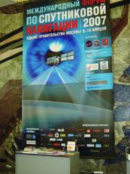
More than 600 delegates registered for the International Satellite Navigation Forum, which featured 87 speakers and three tracks of technical sessions. The event was organized by Profi-T-Centre, a Moscow-based conferencing company, and endorsed by the Russian Federal Space Agency (Roscosmos), the Russian Ministry of Communications and Information, and the Moscow City Government on whose premises the forum took place.
An announcement of a decision to add a CDMA signal to GLONASS that would more closely align the Russian system with GPS and Galileo was not forthcoming at the conference, as many had hoped. Nonetheless, a remarkable number of private companies and public institutes joined the proceedings and discussed their efforts to build and use combined GLONASS and GPS receivers.
Russian President Vladimir Putin has put the restoration of and modernization of GLONASS high on his political agenda and is following its progress closely, a fact underlined by the stature of the officials taking part in the forum: Anatoly Perminov, head of Roscosmos; Yuri Nosenko, Roscosmos deputy chief, head of the GLONASS coordination board, and chairman of the forum’s plenary session; and Lt. Gen. Alexander Kvasnikov, deputy commander of the Russian Space Forces.
They were joined at the opening session by Yuri Urlichich, director general of the Russian Institute of Space Device Engineering (RISDE), which designs the GLONASS space and ground equipment; Nikolai Testoyedov, director general of NPO PM “Reshetnev,” which builds the GLONASS satellites; M. G. Lebedev, a senior advisor to the Russian minister of communications and information; and Sergei Burov, vice-governor of the Yaroslavskaya region near Moscow that has served as a kind of GNSS showcase.
Roscosmos’ Perminov noted, “Development of positioning, navigation, and timing capabilities is one of the top priorities of the Russian Federation, particularly through use of GLONASS as a dual-use system. We have a primary objective of [achieving] compatibility and interoperability with, first, GPS, and, second, Galileo.”
Russia has increased its federal budget allocation for GLONASS to 9.88 billion rubles ($379.7 million) in 2007, more than double the 4.72 billion ruble ($181.4 million) federal expenditure in 2006. Launches of six modernized GLONASS-M spacecraft are scheduled this year — a triple launch in September and another in December.
Despite its international title, the event drew a largely Russian audience, with only a few dozen attendees from outside the country. Nosenko underlined this aspect of the forum, saying, “The primary purpose is to inform a broad Russian audience of satellite navigation and its applications.”
Unlike GNSS conferences in most other venues, the focus was pointedly on Russia’s own GLONASS system. Indeed, although the English translation of the event’s title was “satellite navigation,” the Russian name was “International GLONASS Forum.” (In fact, GLONASS itself is the Russian acronym for Global’naya Navigatsionnaya Sputnikovaya Sistema — or global satellite navigation system.)
Official Imprimatur
Formally enshrined in an April 19, 2006, government directive, Russia’s initiative to develop mass market equipment and applications faces many of the same obstacles to commercialization that GPS has had to overcome during the past 15–20 years and some new challenges as well.
The participation of several high-ranking U.S. officials involved in GPS affairs reflected the growing cooperation in GNSS programs between the two countries: Ken Hodgkins, deputy director of the State Department’s Office of Space & Advanced Technology; Mike Shaw, director of the National Coordination Office for Space-Based Positioning, Navigation, and Timing; and U.S. Air Force Col. Mark Crews, chief engineer at the GPS Wing in the Space & Missile Center, Los Angeles Air Force Base.
“Multiple [GNSS] systems create a winning situation for consumers,” Urlichich said, announcing an initiative to create a GLONASS Forum or what he called “an association of lovers of GLONASS.” By working to make the various systems more compatible and interoperable, Urlichich said, Russia will help lay the foundation for global mass markets. “All together, it will make it possible for mass consumers to have GNSS.”
Russia’s struggle to transform a command economy shaped by more than 70 years of top-down, Communist Party–led governmental planning and direction remains a work in progress. Many of the institutions, terminology, and practices of market-based economies remain unfamiliar to both public officials and nascent businesspeople.
Lebedev, the Communications and Information Ministry advisor, undertook a sort of tutorial on entrepreneurialism and private business in his presentation. “It is necessary,” he told his plenary audience, “to understand the value chain in order to successfully develop markets.”
Lebedev showed several slides from presentations by the Galileo Joint Undertaking and the U.S. Office of Space Commerce to illustrate the GNSS value-added chain and GNSS market projections. Later, he noted that in order to “extract profits in this sector, we need to develop business models.”
Although the level of such discussions might seem basic — even primitive — to Western ears, it does reflect a clear desire to learn how to do business in a completely new way.
Home-Grown GNSS
Perhaps the most notable aspect of the conference emerged in the numerous presentations by domestic Russian companies designing multi-system GNSS receivers and offering GNSS-based services.
Since the dissolution of the Soviet Union, when almost all major manufacturing and business activities were based on government ownership and management, commercial activities have appeared in a variety of forms: privatization of former public enterprises, public/private joint ventures, commercial spin-offs from public institutes, and, increasingly, true private startup companies.
ZAO Navis, for instance, exhibited a variety of GLONASS/GPS products at the forum — mostly larger form factors such ad racks and boards for aviation, commercial vehicle tracking, and synchronizing communications systems.
Adding GLONASS to GPS increases costs by 10–20 percent, according to O. A. Borsuk, chief designer for the 11-year-old Moscow-based design bureau. The company has announced a new GPS/GLONASS module, CH-4706, and plans to bring out a 0.13 micron GPS/Galileo L1 chip in 2008.
Another 13-year-old company, Granit, began developing GPS navigation units in 2001 without government support, E. V. Vikharev, Granit’s deputy director of research, told his forum audience. Characterizing the company’s self-financed progress in post-Soviet Russia as “a difficult experience,” he described four generations of product development, including the current Granit Navigator 04 based on SiRF Technology’s SiRFstarIII.
Vikharev said the company has sold 25,000 units in 15 different models to more than 250 different Russian companies and organizations, including 200 Navigator 02 units installed on city buses in one of Yaroslavl’s projects. Granit has developed a prototype GPS/GLONASS/Galileo and should complete the unit by next year.
RISDE and the St. Petersburg–based Russian Institute for Radionavigation and Time (RIRT), two institutes that have relied on government support for much of their existence, have launched commercial development activities. RISDE’s Urlichich described an agreement signed last month for a “public-private partnership that will develop and produce user equipment.”
S. V. Filantchenkov, deputy chief of RIRT’s research division, traced several generations of GPS/GLONASS receivers developed by the institute since 2004. Known primarily for developing the atomic clocks for GLONASS satellites and ground facilities, RIRT is currently designing a receiver that can process GLONASS M and GPS IIR signals. By next year, Filantchenkov said, the institute’s engineers expect to complete an OEM GPS/GLONASS/Galileo RFIC module that would sell in the $12 range for large volumes.
Telematics services, particularly vehicle tracking/fleet management applications, appear to be the most common GNSS businesses to have developed in Russia so far. The Granit and Navis presentation touched frequently on their telematics products and customers. Other telematics-oriented Russian companies taking part in the forum included M2M, ITS Soft, Geizer, and SecTrack.
A typical business development path for the new enterprises is to secure contracts from public agencies at the federal, state, or local levels to design and install systems. These contracts then establish a foundation for further government contracts and product line extensions.
Lebedev cited “expert opinion” in estimating the current Russian market for GNSS products at up to five million units, primarily in government-regulated commercial and professional markets, including safety and security.
Looking ahead to a true consumer market in Russia, he pointed to two platforms that have incorporated GNSS technology in many other countries: private cars and portable electronic devices. Russia’s automobile market over the next five years is expected to produce sales of two to three million, while 380,000 portable PCs and mobile phones were sold in the country last year.
Although the central government is accumulating large financial reserves from taxes on extraction and exports of natural resources, however, Russia still lacks channels, workplans, and, the experience needed to recycle part of these through the nation’s emerging small and medium enterprises. One promising indication, however, could be found among several representatives of private Russian banks who attended the event to meet with the entrepreneurs and evaluate the prospects for investing in the GNSS businesses.
CDMA: Decision Still to Come
All this GNSS development activity is particularly remarkable considering that GLONASS is a frequency division multiple access (FDMA) system that differs markedly from GPS and Galileo. FDMA is, in fact, the inverse of GPS’s code division multiple access (CDMA) design in which each satellite broadcasts a distinctly coded signal on a common frequency.
In contrast, GLONASS transmits a single code on different frequencies allocated to antipodal sets of GLONASS satellites using two swaths of spectrum — currently from 1598.0625 to 1609.3125 MHz (above GPS L1 centered at 1575.42 MHz) and from 1242.9375 – 1251.6875 MHz for L2 (compared with 1227.6 MHz for GPS L2).
The $64 million question — or, closer to the mark, the $68-billion question (to pick up on Shaw’s projection for the global GNSS market in 2010) — is how compatible the Russians will decide that GLONASS will be. Russia has committed to reaching a decision on the question of adding a CDMA signal by the end of 2007.
Different perspectives and philosophies are competing among the country’s various institutional groups. A new generation of engineers appears inclined to forge greater interoperability with other GNSSes by adding a CDMA signal on a common frequency.
The main arguments raised against CDMA seem to be: single point of failure if all GNSS signals at L1/E1, national security issues, the matter of paying for new civil signal design, and an element of Russian uniqueness.
Numerous GNSS manufacturers — among them JNS, NovAtel, Trimble, Leica, Magellan, and Topcon — already offer combined GPS/GLONASS receivers, typically for professional and commercial activities such as surveying, geodesy, and construction. But such equipment is substantially more complicated in design and expensive — a long way from becoming consumer-friendly.
By having a L1 civil signal apart from the band in which consumers will find most benefit from GPS and Galileo (and, for that matter, China’s Compass GNSS), GLONASS requires manufacturers to widen the reach of their receivers’ antennas and “front-end” components.
As the GPS Wing’s Crews pointed out in his presentation, the key technical issue may be that CDMA-based systems can more easily filter out a common delay in the GNSS time signals on a common frequency. With FDMA systems, he continued, “We can calibrate our filtering for multiple frequencies [and time delays], but it increases costs. That means it’s an issue for making affordable, mass market equipment.”
Nonetheless, the American delegates went out of their way to emphasize that GLONASS signal design questions are completely up to the Russians to sort out.
By