Aerospace and Defense

July 2, 2007

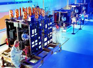
U.S. Air Force Releases GPS Block IIIA Satellite RFP

After several false starts in the previous months and a multi-year delay in the overall GPS III architecture development, the GPS Wing (formerly the GPS Joint Program Office) announced on July 12 the release of a request for proposal for the development and production of the GPS Block IIIA satellites.

Read More >

By Inside GNSS
July 1, 2007

Galileo’s New PPP: Public-Public Partnership?

GSA Executive Director Pedro Pedreira (left) and Guiseppe Viriglio, ESA director of telecom and navigation, at signing of accord

Having abandoned — for the time being at least — attempts to attract private investment to the creation of Galileo’s infrastructure, European GNSS leaders are working to shape a Plan B that can gain support from the program’s extensive group of stakeholders.

Read More >

By Inside GNSS
June 3, 2007

Speaking with Authority: Galileo’s Lead Agency in a Changing World

Sometimes things don’t go as planned.

That certainly is the situation facing the European GNSS Supervisory Authority (GSA) today as the new lead agency for Galileo affairs.

A meltdown of the public private partnership (PPP) that was supposed to build and operate Europe’s GNSS has thrust an unexpected — and unscripted — role into the hands of the GSA almost at the very moment that the new organization first stepped onto the public stage.

As originally envisioned, the GSA — a European community agency operating under the aegis of the European Commission (EC) — had only to “conclude a concession contract with whichever consortium is selected on completion of the development phase of Galileo.”

Not “negotiate” a contract — that was the task of GSA’s predecessor, the Galileo Joint Undertaking (GJU) — but merely sign off on the deal. And then monitor the contract’s implementation on behalf of its public sponsors while taking up a full suite of other tasks.

Instead, on May 11, the GSA Administrative Board delivered its opinion that progress in negotiations with the consortium of eight companies seeking the 20-year concession contract was not making “relevant progress at the level” needed to ensure a timely completion of the Galileo project.

That conclusion by the GSA board, and a set of alternative courses of action, will now go to the European Union (EU) Transport Ministers Council in early June.

At the center of the storm are the GSA and its executive director, Pedro Pedreira, who took up his responsibilities in July 2005. Before his GSA appointment, Pedreira was serving as director of business development at Portugal Telecom, having spent more than 20 years in the satellite communications field.

Still unfamiliar to many in the GNSS community, the GSA has a €420 million budget for 2007, including €40 million in this year’s R&D allocation from the EC’s 7th Framework Program. An administrative board with representatives from the EU’s 25 member states oversees the authority. Unlike many European Community institutions, however, the board only requires two-thirds majorities for its decisions, which should enable it to act quickly and powerfully.

Although he has been at the GSA nearly two years, it was only upon the “liquidation” of the GJU in January that Pedreira and his organization became truly visible. During the interim, his focus was on building a staff with “critical mass” — now numbering about 50 — and preparing for the authority’s role as the lead agent for supervising implementation of Galileo and monitoring compliance of a Galileo Operating Company (GOC) with the concession contract.

In a series of exclusive conversations with Pedreira and key GSA staff members in March and May, Inside GNSS explored the agency’s mission and the implications of a potentially strategic change of direction for the Galileo program and the authority’s role.

European sources close to the concession negotiations have told Inside GNSS that the leading alternate approach to a PPP is an outright public takeover of the project now and issuance of a new tender for a private operator once most or all of the Galileo space and ground infrastructure is built.

Pedreira would not discuss the specifics of any of the proposed alternatives before they are presented to the transport ministers in June. However, he acknowledged that “the original mandate [to the GSA] was based on a certain model – PPP.” Depending on the decision reached by the transport ministers, “The Council may look at the governance of the program and adjust the mandate of the GSA.”

More, and Then Less

As laid out in a July 12, 2004, EU Council regulation establishing the GSA, the first order of business for the authority was to “conclude a concession contract with whichever consortium is selected on completion of the development phase of Galileo and take steps to ensure compliance by that consortium with the obligations — in particular the public service obligations — arising from the concession contract.”

Because at the time it went out of business the GJU had only managed to thrash out a “head of terms” agreement — essentially, the chapter headings and outline of points for an eventual contract — it initially appeared that GSA would be saddled with a lengthy negotiation with the private consortium. Instead, by the time of the Munich Satellite Navigation Summit in early March, Pedreira and EC Director-General for Transport and Energy Matthias Ruete were decrying the failure of the consortium to incorporate, appoint a CEO, and finish talks on the concession contract.

At a March 22 meeting, the transport ministers gave the consortium until May 10 to meet a series of milestones, leaving it to the EC, “assisted by GSA and ESA [the European Space Agency], to assess progress in the concession negotiations and to submit alternative scenarios, also assessed for costs, risk, and affordability,” in time for their June council meeting.
“The council in March noted its previous decision to implement the project with PPP,” says Pedreira. “But we could have a different geometry of partnership [with the private sector]. It could have a different shape.”

So, what happens to GSA if the transport council (and probably the Ministers Council — heads of state of the 25 EU members) drops or delays implementation of the PPP concept and goes for an public sector–only plan?

“It’s too soon to see how to adjust forms of the current organization,” says Pedreira. “The concession has taken a considerable amount of our resources. We have been giving a priority to the concession [since GSA was established].”
Indeed, supporting the GSA concession effort, headed by Carlo des Dorides who had served as chief negotiator with the GJU, was at the top of several other GSA administrators’ agendas.

In a March interview, Gian Gherado Calini, head of market development, told Inside GNSS that his group had two main tasks: first, the concession and working with des Dorides to identify size and growth of those markets supported by services operated by the concession. Second came downstream markets and creating conditions for them to succeed.

At that time, Hermann Ebner, head of the largest GSA unit, the Technical Department, put support for the concession process at the top of his list as well. A GSA technical task force had completed an assessment of design risks, and the department handled design revisions proposed by the consortium and kept a running tab on the changing cost figures associated with the program.

Even the security section had a role through the PACIFIC project to size the potential markets for the publicly regulated service (PRS), an encrypted signal designed for public safety, law enforcement, and possibly military applications.

Still Plenty to Do

Although the concession headed the list of GSA responsibilities, it is far from the only task given the agency by the 2004 regulation.

“Many aspects of GSA role are independent of the procurement model,” Pedreira says, ticking off some of the others that are top of mind: Galileo security, frequency coordination, management of R&D programs, and integration of the European Geostationary Navigation Overlay Service (EGNOS, essentially a satellite-based augmentation system) into the Galileo infrastructure and operations.

In the matter of market development, for instance, Pedreira points out, “The business plan of the concession internalized only a fraction of the public activity [in application markets].” The Open Service, from which an overwhelming portion of Galileo market revenues will come, was not part of the concession’s mandate. That represents, in Calini’s words, “a gold mine” of potential new services and products.

Getting Technical
. Meanwhile, the EC 7th Framework Program has allocated a total of €350 million over the next seven years for R&D projects under the GSA’s control, plus any still-uncompleted FP6 projects taken over from the GJU. The first calls for tenders on FP7 projects this year will target applications, receiver development, and Galileo implementation, says Ebner.

Another large item on Ebner’s agenda, regardless of GSA’s partner in moving Galileo forward, is system definition and development. On May 11, the agency published announcements for a system definition and performance head, a space segment implementation officer, and a ground mission segment implementation officer.

Other major tasks for the GSA Technical Department include managing the Galileo signal Interface Control Documents (ICDs) and frequency coordination. At its March 21 meeting, the GSA Administrative Board issued notice of an intention to proceed with implementing the multiplexed BOC waveform that will serve as the basis not only for Galileo Open Service signals but the new GPS civil signal at the L1 frequency (L1C).

Unlike the GJU, GSA can sign contracts and handle international agreements previously overseen by other EC departments. It has taken over from the GJU the responsibility for keeping track of projects by the People’s Republic of China, Israel, and other co-investors in Galileo.

Keeping Galileo Safe.
Nearly untouched by the success or failure of the concession is the GSA’s role regarding security for the Galileo system — including space, ground, and user segments. “Galileo is the first EU space program for which security was needed,” says Olivier Crop, the agency’s PRS officer.

The GSA has created a System, Safety, and Security Committee (3SC), which will be a key player in EU decisions on Galileo. The authority also will be responsible for establishing a Galileo Security Center charged with helping protect the system’s critical infrastructure, controlled signals, and PRS-capable user equipment.

EC policy on PRS, which was only approved for inclusion in Galileo in 2004, lets every member nation decide whether they want to allow use of PRS within their own “sovereignty domain.” Each country controls access to its own receivers, but operations in other countries or throughout the EU generally requires approval of the European Council.

EGNOS.
The 2004 council regulation also entrusted the GSA with “managing the agreement with the economic operator charged with operating EGNOS and of presenting a framework on the future policy options concerning EGNOS,” which is largely complete and in provisional operation.

In 2004, with the incorporation of EGNOS into the concession, Pedreira says, came the recognition “that the consortium could not tackle [operating EGNOS] as soon as hoped. There was a need to go for an open tender on EGNOS economic operation.”

EGNOS, in fact, was a subject of discussion at the GSA board’s May 11 meeting. “There are many aspects to settle,” says Pedreira — issues involving ESA and the aviation organizations that are co-owners of EGNOS with the EU. “We will need to transfer assets to GSA to proceed with an open tender” for a service provider to implement early operation of EGNOS.
“At the working level, GSA has very good, very intense relations with ESA, especially on EGNOS and IOV,” he adds.

The GSA is also charged with responsibilities during the in-orbit validation (IOV) phase of Galileo’s development, although ESA is in charge of the technical side of things. “It would be surprising if the council went for a solution without taking note of the progress on the IOV phase and making best use of the assets and investment made to date.”

Perhaps most significantly, under the 2004 council regulation the GSA owns the tangible and intangible assets created during the development and implementation phases of the program. In other words, the agency is the legal guardian of the public interest in Galileo.

Overhanging that role, of course, is what the GSA’s political masters — initially, the transport ministers and, ultimately, the member states — decide to do about Galileo as a whole.

By Inside GNSS
[uam_ad id="183541"]
April 6, 2007

Two for One: Tracking Galileo CBOC Signal with TMBOC

On-going discussions are taking place between U.S. and European Union (EU) experts concerning the future GPSIII L1C and Galileo E1 OS civil signals. An agreement on a common power spectral density (PSD) known as multiplexed binary offset carrier (MBOC) recently emerged as a solid candidate to replace the current baseline: BOC(1,1).

On-going discussions are taking place between U.S. and European Union (EU) experts concerning the future GPSIII L1C and Galileo E1 OS civil signals. An agreement on a common power spectral density (PSD) known as multiplexed binary offset carrier (MBOC) recently emerged as a solid candidate to replace the current baseline: BOC(1,1).

In order to comply with the MBOC PSD, two candidate implementations, known as time-multiplexed BOC (TMBOC) and composite BOC (CBOC) modulations, have been proposed. If fully exploited, these implementations will provide improved performance but require a more complex receiver architecture than a BOC(1,1) receiver.

Increased complexity and associated higher costs, however, might be detrimental for a GNSS receiver manufacturer that would like to use MBOC, but with limited modifications to their receivers — particularly for those companies producing equipment for mass consumer markets. This article aims at evaluating a new CBOC receiver architecture using locally generated TMBOC-like signals that will result in a simpler architecture comparable to a BOC receiver.

The normalized MBOC PSD includes the whole of GPSIII L1C or Galileo E1 OS civil signals, which means both their data and pilot components.

Because the MBOC is defined only in the frequency domain, a variety of compliant temporal modulations can be used. In the literature, two different modulations were proposed to implement the MBOC:
• TMBOC, which multiplexes in the time domain BOC(1,1) and BOC(6,1) sub-carriers and seems likely to become the main candidate used by the future GPSIII L1C signal, and
• CBOC, which linearly combines BOC(1,1) and BOC(6,1) sub-carriers (both components being present at all times), and appears to be the leading candidate for the Galileo E1 OS signal.

The Additional Resources section lists papers by G. Hein et al, J. Betz et al, and J.-A. Avila-Rodriguez et al, which introduce and discuss TMBOC and CBOC in detail. (Available in the downloadable PDF, above.)

The philosophy behind these two modulations is very different, and, although they would theoretically produce equivalent tracking when used with a TMBOC or CBOC receiver (considering pilot and data channels), they can result in different performances in other configurations (for instance, considering the pilot channel only).

A major difference between the TMBOC and CBOC modulations is that the CBOC sub-carrier, as the weighted sum of two squared-wave sub-carriers, will have four different levels. Consequently, this means that an optimal CBOC receiver has to generate a local replica that also has four levels, resulting in a local replica encoded on more than just one bit. This could complicate the CBOC receiver architecture and might prove detrimental to the widespread use of this modulation for certain types of receiver, if retained as the Galileo E1 OS modulation.

This article describes an innovative technique that only requires a 1-bit local replica, very similar to a TMBOC waveform, to track CBOC signals. This method is particularly interesting because, despite its simple implementation, it has only limited losses in tracking performance with respect to traditional CBOC or TMBOC receivers. Moreover, it shows excellent performance when compared to the previous GPS/Galileo L1 baseline signal, the BOC(1,1).

The first part of this article describes the possible CBOC and TMBOC candidates for Galileo E1 OS and GPS III L1C modulations. The second part looks at the traditional tracking performances of these two modulations in terms of thermal noise and multipath-induced errors.

Finally, we introduce the new 1-bit tracking technique and compare it against optimal CBOC and TMBOC tracking in terms of tracking noise and multipath resistance.

Conclusions
Following the US/EU MBOC agreement, the current main candidates for the GPSIII L1C and Galileo E1 OS have been introduced. In particular, the pilot channels have been analyzed with their use of the new CBOC and TMBOC modulations.

Although adding a very small amount of BOC(6,1) to the previous BOC(1,1) baseline, it has been shown that the tracking performances of these future signals are significantly improved compared to pure BOC(1,1) tracking. In particular, tracking noise is reduced by 2.4 to 3 dBs in terms of equivalent C/N0, and multipath mitigation is significantly improved.

Focusing on the CBOC modulation, its multi-level waveform could result in more challenging receiver architecture. In order to keep a simple receiver design to receive a CBOC signal, a new tracking technique, referred to as TM61, has been proposed to allow tracking of the CBOC modulation with a 1-bit only locally generated replica. This method uses time-multiplexing of BOC(1,1) and BOC(6,1) sub-carrier on the same model as the TMBOC modulation.

A preferred implementation of TM61 is the use of a pure BOC(1,1) sub-carrier for the prompt correlators and a pure BOC(6,1) sub-carrier for the early and late correlators (a DP discriminator being assumed). This yields a much simpler receiver architecture since it requires only pure sub-carriers with no-multiplexing (different from TMBOC receivers), 1-bit local replicas (unlike a CBOC local replica) and a minimum of correlators. Please note it is also possible to use another implementation of the TM61 tracking methods with time-multiplexing.

In its preferred implementation, TM61 brings only a slight post-correlation SNR degradation (about 0.35 dBs for the selected CBOC main candidate for Galileo pilot channel), enabling good phase tracking. TM61 code tracking noise performance is degraded with respect to traditional CBOC tracking by approximately 2.4 dBs. However, this has to be put into perspective considering the substantial reduction in receiver complexity with TM61 and the fact that thermal noise might not be the main source of error for many applications.

Finally, the TM61 tracking technique has been demonstrated to provide, in its preferred implementation, a better multipath resistance compared to traditional CBOC tracking. In any case, the use of TM61 to receive a CBOC signal has been shown to significantly outperform the traditional reception of a pure BOC(1,1) with equivalent power, thus supporting the use of the modernized CBOC signal. Consequently, it seems to be a very good tracking technique for implementation in future CBOC receivers.

For the full article, including graphs, figures, and additional resources, download the PDF above.

By

Enhancing the Future of Civil GPS: Overview of the L1C Signal

The Global Positioning System is undergoing continual modernization, providing ongoing improvements for users worldwide. Although various enhancements in system features have been under development since the mid-1990s, modernization first benefited civil users when Selective Availability — a security-motivated technique for “dithering” the open L1 signal to reduce positioning accuracy — was set to zero in May 2000.

The Global Positioning System is undergoing continual modernization, providing ongoing improvements for users worldwide. Although various enhancements in system features have been under development since the mid-1990s, modernization first benefited civil users when Selective Availability — a security-motivated technique for “dithering” the open L1 signal to reduce positioning accuracy — was set to zero in May 2000.

Subsequently, other improvements in accuracy have been obtained through enhancements to the capabilities and operation of the control and space segments, still based on the original set of GPS signals.

The launch of the IIR-14(M) (modernized replenishment satellite) in 2005 began a new era with transmission of the L2 civil (L2C) signal, along with the modernized military M-code signal. A third civil signal, called L5, will be transmitted from Block IIF satellites.

All the while, improvements in monitoring, satellite technology (for example, the on-board atomic clocks) and operations yield continuing increases in accuracy. The United States plans to continue providing these capabilities free of user fees. It will continue to complement this pricing policy by providing free and open signal descriptions and other technical information needed for development of receivers and services using civil signals.

In the meantime, development of the next generation of satellites, called GPS III, and a modernized control segment (OCX) continues, which will lead to greatly enhanced capabilities beginning early in the next decade. An integral part of the GPS III capabilities being developed is a new civil signal, called L1C, which will be transmitted on the L1 carrier frequency in addition to current signals.

Approximately one year ago, the U.S. Air Force released the initial draft of Interface Specification IS-GPS-800, describing L1C. Novel characteristics of the optimized L1C signal design provide advanced capabilities while offering to receiver designers considerable flexibility in how to use these capabilities.

The development of L1C represents a new stage in international GNSS: not only is the signal being designed for transmission from GPS satellites, its design also seeks to maximize interoperability with Galileo’s Open Service signal. Further, Japan’s Quazi-Zenith Satellite System (QZSS) will transmit a signal with virtually the same design as L1C.

L1C has been designed to take advantage of many unique opportunities. Its center frequency of 1575.42 MHz is the pre-eminent GNSS frequency for a variety of reasons, including the extensive existing use of GPS C/A code, the lower ionospheric error at L1 band relative to lower frequencies, spectrum protection of the L1 band, and the use of this same center frequency by GPS, Galileo, QZSS, and satellite-based augmentation system (SBAS) signals for open access service and safety-of-life applications.

Other unique opportunities that the L1C design leverages include advances in signal design knowledge, improvements in receiver processing techniques, developments in circuit technologies, and enhancements in supporting services such as communications. The L1C design has been optimized to provide superior performance, while providing compatibility and interoperability with other signals in the L1 band.

L1C provides a number of advanced features, including: 75 percent of power in a pilot component for enhanced signal tracking, advanced Weil-based spreading codes, an overlay code on the pilot that provides data message synchronization, support for improved reading of clock and ephemeris by combining message symbols across messages, advanced forward error control coding, and data symbol interleaving to combat fading.

The resulting design offers receiver designers the opportunity to obtain unmatched performance in many ways.This article will give an overview of the L1C signal design, highlighting the features that will benefit receiver designers and, ultimately, end users. The following section provides background on L1C and its design process, from its beginnings in 2003.

Subsequent sections then provide an overview of the signal structure, details of the signal’s spreading codes and overlay codes, spreading modulation, data message structure, and encoding and decoding of message information.

Summary of Benefits
Although more complete details are provided in IS-GPS-800, we will outline the most significant characteristics here.

L1C has been designed with unique, innovative, and powerful new features to enhance its robustness for all users, especially in difficult environments.

The signal structure alone, with the spreading code and the overlay code, provides exact GPS time, modulo 18 seconds. Alignment to the spreading code provides bit synchronization and alignment to the overlay code provide frame synchronization, making these receiver functions simple and robust.

For high-precision (e.g., survey) use, the pilot carrier removes the half cycle phase ambiguity, and the larger RMS bandwidth of the new spreading modulation has the potential to improve tracking performance, especially multipath mitigation. With the combination of improved carrier tracking of the pilot component, segmentation of clock and ephemeris in the data message, and FEC design, an autonomous navigator can demodulate the satellite clock and ephemeris whenever the signal can be tracked.

The improved cross-correlation of the new codes will also improve the performance of high-sensitivity receivers. Performance will also improve as a result of the new message format that allows code combining across satellites for the TOI and code combining of the near constant sub-frame 2 ephemeris data across multiple frames. International collaboration and outreach have assisted in producing a truly international signal with capabilities that will serve users for decades to come.

For the full article, including figures, graphs, and additional resources, download the PDF above.

By
[uam_ad id="183541"]
March 2, 2007

More Perils for Galileo . . . and Other GNSS Dramas

A convergence of developments over the past few months has brought Europe’s Galileo program to the most critical passage of its history — at least, since final approval of the GNSS initiative by the European Space Agency (ESA) and the European Union (EU) in 2003 and 2004, respectively.

Read More >

By Inside GNSS
January 31, 2007

GPS Block III Contracts

The U.S. Air Force has awarded two $50 million contracts to Boeing and Lockheed Martin to execute a system design review for the next-generation GPS space segment program, GPS Block III.

The contracts come on the heels of both companies successfully completing system requirements reviews in November 2006. Those reviews, part of a $10 million follow-on order to a Phase A Concept Development Contract awarded in 2004, assessed Boeing’s and Lockheed’s ability to mitigate development and delivery risks associated with building the Block III satellites.

Read More >

By Inside GNSS
October 1, 2006

GPS: Launches of Satellites and Institutional Initiatives

Successful launch of the second modernized Block IIR satellite, IIR-15(M2), on September 25 and scheduling of another IIR-M launch on November 14 underlines recent progress in the GPS program.

IIR-15(M2), also identified by its space vehicle number (SVN58) and pseudorandom code number (PRN31), will be placed into orbital plane A, slot 2. The U.S. Air Force has designated the satellite to be launched in November as GPS IIR-16/M3, PRN15/SVN55.

Read More >

By Inside GNSS

Correlators for L2C

The term “Correlator” is often used in discussions of GPS and GNSS receiver design. It has been used to describe devices as simple as a single exclusive OR gate through to complete “baseband” chips that include a microprocessor.

Most usually, and in this article, the term describes the hardware or software that produces all of the required correlation data for a single signal from a specific GNSS satellite signal. This is also sometimes termed a “channel.”

The term “Correlator” is often used in discussions of GPS and GNSS receiver design. It has been used to describe devices as simple as a single exclusive OR gate through to complete “baseband” chips that include a microprocessor.

Most usually, and in this article, the term describes the hardware or software that produces all of the required correlation data for a single signal from a specific GNSS satellite signal. This is also sometimes termed a “channel.”

With the open GPS civil signal at the L2 frequency (L2C) now becoming available on Block IIR-M satellites, receiver designers have the opportunity to work with a markedly different GNSS signal resource. The first IIR-M spacecraft (designated SVN53/PRN17) was launched September 25, 2005, and the second is scheduled to go into orbit on September 14, 2006. (IIR-Ms also transmit the new GPS L1/L2 military (M-code) signal, but we will not treat this issue here.)

Against that historic backdrop, then, this article examines some of the novel elements of the L2C signal and its implications for GNSS receiver correlators. Our focus will be on a technically challenging aspect of receiver operation: initial acquisition of the signal and its processing by the correlator.

But first we will review some of the key functional aspects of GNSS correlators and some of the signal parameters that affect their operation.

. . . We can more easily explain the role of a correlator if we examine its two functions separately. In a GNSS receiver, correlation is used in two distinct activities:

Acquisition. Before the receiver knows whether it can receive a certain satellite’s signal, it must “search” for it using the correlation in an ordered but relatively indiscriminate way. Effectively, many correlation trials are run for each of many code delays and Doppler frequency offsets.

Tracking. Once acquired, the receiver must still despread the received signal in order to receive data and measure pseudoranges. Several correlators are usually used to keep the local code as closely aligned to the received code as possible. To do this, a “delay-locked loop” is used, with the correlators operating within the loops, some typically ahead of the received code (“early”) and some behind (“late”).

In other words, correlation is used both to “get” the signal and to “keep” it. These actions should be considered quite separately. In this article, we concentrate on the acquisition process.

. . . Various signal parameters affect correlation. These are listed for the three GPS signals in Table 1. Both L2C and L5 have dataless sub-signals which are time-multiplexed (CM and CL) and in quadrature (I5 and Q5), respectively. Both use longer codes than L1, while L5 has a higher chipping rate. L5 also has the added complication of Neuman-Hoffman codes, which will not be further discussed here.

. . . Correlation Signal “Shape” – the L1 civilian C/A-code signal is a single BPSK modulation. Despite the fact that the L2C signal is also BPSK, it introduces another layer of complexity by having the data-carrying and dataless signals multiplexed in time. Typically, the shorter (20-millisecond) data-carrying CM code will be acquired first, then the receiver would hand over to the longer (1.5-second) dataless CL code for tracking.

. . . The beauty of the exploitation of the circular convolution is that the code in the data does not need to be well aligned with the stored data— the whole point of acquisition, after all, is to perform this alignment. So, if the CM code was chopped up into pieces smaller than 20 milliseconds, this circular convolution would no longer reflect the time domain correlation, and a receiver would need to have many stored codes.

. . . Many GPS chipsets are optimized for operation in mobile telephone handsets and, as such, are aimed at minimizing the drain on handset batteries. For such applications, the large L2C acquisition overhead presents a serious problem . .

Conclusion
In this article, we have primarily examined the implications of signal acquisition for the new L2C signal. In a typical L2C-only receiver, significantly more effort is required to acquire the signal than is the case for L1 C/A code: more than 200 times higher in the hardware case and more than 500 times higher in the software case. However, because the long CL code does not carry any data, it can be used for the long integrations required for acquisition in a weak-signal environment.

For the complete story, including figures, graphs, and images, please download the PDF of the article, above.

Acknowledgments
The author wishes to acknowledge the useful suggestions made by Eamonn Glennon of Signav Pty Ltd.

By
July 1, 2006

BOC or MBOC?

Europe and the United States are on the verge of a very important decision about their plans to implement a common civil signal waveform at the L1 frequency: Should that waveform be pure binary offset carrier — BOC(1,1) — or a mixture of 90.9 percent BOC(1,1) and 9.09 percent BOC(6,1), a combination called multiplexed BOC (MBOC). The desire for a common civil L1 signal is enshrined in a 2004 agreement on GNSS cooperation between the United States and the European Union (EU).

Europe and the United States are on the verge of a very important decision about their plans to implement a common civil signal waveform at the L1 frequency: Should that waveform be pure binary offset carrier — BOC(1,1) — or a mixture of 90.9 percent BOC(1,1) and 9.09 percent BOC(6,1), a combination called multiplexed BOC (MBOC). The desire for a common civil L1 signal is enshrined in a 2004 agreement on GNSS cooperation between the United States and the European Union (EU).

For the EU and the European Space Agency (ESA), that decision — and its consequences — will come sooner: with the Galileo L1 Open Service (OS) that will be transmitted from satellites to be launched beginning in the next few years. For the United States, the waveform decision will shape the design of the L1 civil signal (L1C) planned for the GPS III satellites scheduled to launch in 2013. For a background on the process that led to design of the GPS L1 civil signal and its relevance to the BOC/MBOC discussion, see the sidebar L1C, BOC, and MBOC.

The May/June issue of Inside GNSS contained a “Working Papers” column titled, “MBOC: The New Optimized Spreading Modulation Recommended for Galileo L1 OS and GPS L1C”. Authored by members of a technical working group set up under the U.S./EU agreement, the article discussed the anticipated MBOC benefits, primarily improved code tracking performance in multipath. The column also noted that, while lower-cost BOC(1,1) receivers would be able to use MBOC, it would come at the cost of a reduction in received signal power.

An article in the “360 Degrees” news section of the same issue of Inside GNSS noted that some GNSS receiver manufacturers believe MBOC is not best for their applications and perhaps should not have been recommended. (This point was noted on page 17 of the May/June issue under the subtitle “MBOC Doubters.”) See the sidebar “Other Observers” (below) for additional comments from companies with concerns about MBOC recommendation.

This article, therefore, continues the discussion of a common signal waveform by asking several companies with different product perspectives whether they consider the proposed MBOC waveform to be more or less desirable for their applications than the BOC(1,1). Currently, BOC (1,1) is the baseline defined in the June 26, 2004, document signed by the U.S. Secretary of State and the vice-president of the European Commission (the EU’s executive branch): “Agreement on the Promotion, Provision and Use of Galileo and GPS Satellite-Based Navigation Systems and Related Applications.”

Maximum benefit from MBOC will be obtained by receivers using recently invented technology that employs computationally intensive algorithms. Although such receivers clearly will provide benefits to their users because of the BOC(6,1) component of MBOC, the practical value of the benefits have not been quantified, which is one purpose of the questions raised in this article. For the moment, let’s call all these prospective MBOC users “Paul”.

Meanwhile, patents on the most widely used multipath mitigation technologies today, such as the “narrow correlator” and the more effective “double-delta” techniques, will expire about the time the new signals are fully available, making these techniques more widely available. Unfortunately, the double-delta technology cannot use the BOC(6,1) component of MBOC. In addition, narrowband receivers, which today dominate consumer products, also cannot use the BOC(6,1). Let’s call all these users “Peter”.

Therefore, the fundamental question raised by this article is whether we should rob Peter to pay Paul. If the amount taken is quite small and the benefits are large, then the answer should be “yes.” If the amount taken creates a burden to Peter, now and for decades to come, with little benefit to Paul, then the answer should be “no.” The in-between cases are more difficult. The purpose of this article is to explore the tradeoffs.

To address this issue, we invited engineers from companies building a range of GNSS receivers to take part in the discussion. We’ll introduce these participants a little later. But first, let’s take a look at the technical issues underlying the discussion.

BOC/MBOC Background

The RF spectrum of a GPS signal is primarily defined by the pseudorandom code that modulates its carrier and associated data. A pseudorandom code appears to be a completely random sequence of binary values, although the sequence actually repeats identically, over and over.

For the C/A code on the L1 frequency (1,575.42 MHz), the state of the code (either +1 or –1) may change at a clock rate of 1.023 MHz. We call this binary phase shift keying, or BPSK(1), meaning BPSK modulation with a pseudorandom code clocked at 1.023 MHz. Note that the bits of a pseudorandom code often are referred to as “chips,” and four BPSK chips are illustrated at the top of Figure 1. (To view any figures, tables or graphs for this story, please download the PDF version using the link at the top of this article.)

Among many other topics, the 2004 U.S./EU agreement settled on a common baseline modulation for the Galileo L1 OS and the GPS L1C signals: BOC(1,1). (The BOC(n,m) notation means a binary offset carrier with n being a 1.023 MHz square wave and m being a 1.023 MHz pseudorandom code.) Like BPSK(1), the BOC(1,1) waveform also is a BPSK modulation, meaning there are only two states, either a +1 or a –1. The timing relationships of the code and the square wave are illustrated by Figure 1.

Although the agreement defined BOC(1,1) as the baseline for both Galileo L1 OS and GPS L1C, it left the door open for a possible signal “optimization” within the overall framework of the agreement. As documented in the paper by G.W. Hein et al., “A candidate for the GALILEO L1 OS Optimized Signal” (cited in the “Additional Resources” section at the end of this article) and many other papers, the EC Signal Task Force (STF) after much study initially recommended a composite binary coded symbols (CBCS) waveform.

Because the agreement made it desirable for GPS L1C and Galileo L1 OS to have an identical signal spectrum and because GPS III implementation of CBCS would be difficult, a search was made by a joint EC/US working group to find an optimized signal that was acceptable for both GPS and Galileo. The result is MBOC (discussed in the May/June “Working Papers” column and the like-named IEEE/ION PLANS 2006 paper by G. W. Hein et al. cited in “Additional Resources.”).

Like all modernized GPS signals — including M-code, L2C, and L5 — L1C will have two components. One carries the message data and the other, with no message, serves as a pilot carrier. Whereas all prior modernized GPS signals have a 50/50 power split between the data component and the pilot carrier, L1C has 25 percent of its power in the data component and 75 percent in the pilot carrier.

The L1C MBOC implementation would modulate the entire data component and 29 of every 33 code chips of the pilot carrier with BOC(1,1). However, 4 of every 33 pilot carrier chips would be modulated with a BOC(6,1) waveform, as illustrated in Figure 2. The upper part of the figure shows 33 pilot carrier chips. Four of these are filled to show the ones with the BOC(6,1) modulation. Below the 33 chips is a magnified view of one BOC(1,1) chip and one BOC(6,1) chip.

The BOC(1,1) chip is exactly as illustrated in Figure 1 while the BOC(6,1) chip contains six cycles of a 6.138 MHz square wave. With this image in mind, we can easily calculate that the pilot carrier has 29/33 of its power in BOC(1,1) and 4/33 of its power in BOC(6,1). Because the pilot carrier contains 75 percent of the total L1C signal power, then the percent of total BOC(6,1) power is 75 × (4/33) or 9.0909+percent. Conversely, the data signal has 25 percent of the total L1C signal power; so, the calculation of BOC(1,1) power is 25 + 75 × (29/33) or 90.9090+ percent.

Because the Galileo OS signal has a 50/50 power split between data and pilot carrier, the implementation is somewhat different in order to achieve the same percentages of BOC(1,1) and BOC(6,1) power. For the most likely time division version of MBOC for Galileo, 2 of 11 chips in the pilot carrier would be BOC(6,1) with none in the data component. Thus, the percent of total BOC(6,1) power is 50 × (2/11) or 9.0909+ percent. Similarly, the percent of total BOC(1,1) power is 50 + 50 × (9/11) or 90.9090+ percent. This makes the spectrum of Galileo L1 OS the same as GPS L1C.

Code Transitions. The fundamental purpose of MBOC is to provide more code transitions than BOC(1,1) alone, as is evident in Figure 2. (A code loop tracks only the code transitions.) However, these extra transitions come on top of the increased number in BOC(1,1) compared to the L1 C/A signal.

Taking into account that the pilot carrier has either 75 percent of the signal power with GPS or 50 percent with Galileo, GPS with BOC(1,1) has 2.25 times more “power weighted code transitions” than C/A-code (a 3.5-dB increase). Galileo with BOC(1,1) has 1.5 times more (a 1.8-dB increase). MBOC on GPS would further increase the net transitions by another factor of 1.8 (2.6-dB increase), and the most aggressive version of MBOC on Galileo would increase the net transitions by a factor of 2.2 (3.4-dB increase).

Therefore, given the improvement of BOC(1,1) over C/A code, the question raised by this article is whether a further improvement in number of transitions is worth subtracting a small amount of signal power during all signal acquisitions, for all narrowband receivers, and for all receivers using the double-delta form of multipath mitigation.

A portion of Table 1 from the May/June “Working Papers” column is reproduced here, also as Table 1. Of the eight possible waveforms in the original table, only three are included here. These are representative of all the options, and they include the two versions of MBOC considered most likely for implementation in Galileo and the only version GPS would use.

Two new columns have been added in our abbreviated version of the table. The first is an index to identify the particular option, and the last identifies whether GPS or Galileo would use that option.

Receiver Implementations

Most GNSS receivers will acquire the signal and track the carrier and code using only the pilot carrier. For GPS L1C this decision is driven because 75 percent of the signal power is in the pilot carrier. Little added benefit comes from using the data component during acquisition and no benefit for code or carrier tracking, especially with weak signals.

For Galileo, the decision is driven by the data rate of 125 bits per second (bps) and the resulting symbol rate of 250 symbols per second (sps). This allows only 4 milliseconds of coherent integration on the Galileo data component (compared with 10 milliseconds on the GPS data component). Because coherent integration of the pilot carrier is not limited by data rate, it predominantly will be the signal used for acquisition as well as for carrier and code tracking.

Reflecting the reasons just stated, Figure 3 compares the spectral power density in the pilot carrier for each of the three signal options listed in Table 1. In each case the relevant BOC(1,1) spectrum is shown along with one of the three MBOC options. These plots show power spectral density on a linear scale rather than a logarithmic dB scale, which renders small differences more prominent.

The center panel shows the GPS case with either BOC(1,1) or TMBOC-75. (The BOC(1,1) peaks are arbitrarily scaled to reach 1.0 Watt per Hertz (W/Hz). The BOC(1,1) peaks of TMBOC-75 are lower by 12% (-0.6 dB) in order to put additional power into the BOC(6,1) component of TMBOC-75, primarily at ±6 MHz.

All three panels of Figure 3 have the same relative scaling. The reason the peaks of the BOC(1,1) components in panels 1 and 3 are at 0.67 W/Hz is that GPS L1C will transmit 75 percent of its total signal power in the pilot carrier whereas Galileo will transmit 50 percent. The difference is simply 0.5/0.75 = 0.67 (-1.8 dB).

The first panel of Figure 3 also shows the Galileo TMBOC-50 option in which the BOC(1,1) component peaks are lowered by 18 percent (-0.9 dB) in order to provide power for the BOC(6,1) component, primarily at ±6 MHz.

The third panel shows the same Galileo BOC(1,1) power density but with the CBOC-50 option. In this case the BOC(6,1) component exists in the data channel as well as the pilot carrier. That is why it is half the amplitude at ±6 MHz as in panels 1 and 2. That also is why less power is taken from the BOC(1,1) component for the BOC(6,1) component; in this case the reduction is 9 percent (-0.4 dB). This is not considered an advantage by those who want to track the BOC(6,1) component, and it also reduces the data channel power for narrowband receivers by the same 9 percent or 0.4 dB.

As stated before, the fundamental question raised by this article is whether we should rob Peter to pay Paul. As with all such top-level questions, the answers lie in the details and in the perceptions of those affected. Inside GNSS posed a series of questions to industry experts in order to explore their perspectives and preferences.

The Questions and Answers

Q: What segment of the GNSS market do your answers address? Describe your market, including typical products and the size of the market.

Fenton – High precision survey and mapping, agriculture/machine control, unmanned vehicles, scientific products, and SBAS ground infrastructure where centimeter accuracy is very important. NovAtel sells at the OEM level to software developers and system integrators and calculates its present total addressable market (TAM) at $300-$400 million USD, again at the OEM level.

Garin – We are focused on consumer electronics where very low cost and very low power are of critical importance, such as personal navigation devices (PNDs), cellular phones, and in general applications where the power consumption is at a premium. These objectives should be reached with little to no impact on the user experience. The loss of performance due to design tradeoffs is mitigated by assisted GPS (A-GPS).

Hatch /Knight – NavCom supplies high-precision, multi-frequency GNSS receivers that employ advanced multipath and signal processing techniques, augmented by differential corrections from our StarFire network. These receivers are widely used in the agriculture, forestry, construction, survey, and offshore oil exploration markets. Current market size is on the order of 100,000 units per year.

Sheynblat/Rowitch – Our answers address wireless products for the consumer, enterprise, and emergency services markets. There are over 150 million Qualcomm GPS enabled wireless handsets in the market today, and this large market penetration and heavy usage is primarily driven by low cost, low power, and high sensitivity. The vast majority of other GPS enabled consumer devices worldwide are also cost driven.

Stratton – Rockwell Collins is a leading provider of GPS receivers to the U.S. military and its allies, and we are also a major supplier of GNSS avionics to the civil aviation industry. The civil aviation applications demand high integrity and compatibility with augmentation systems, while the military requirements range from low-power, large-volume production to high-dynamic and highly jam-resistant architectures (as well as civil compatible receivers). Military receivers are impacted due to civil compatibility requirements. Our company has produced over a half million GPS receivers and has a majority market share in military and high-end civil aviation (air transport, business, and regional) markets.

Studenny – Our market is commercial aviation where continuity of operation and integrity are the most important performance parameters.

Weill – I and a colleague, Dr. Ben Fisher, of Comm Sciences Corporation, are the inventors of a new multipath mitigation approach which we call Multipath Mitigation Technology (MMT), so our primary product is technology for improved multipath mitigation. MMT is currently incorporated in several GPS receivers manufactured by NovAtel, Inc. Their implementation of MMT is called the Vision Correlator.

Q: Which signal environments are important for your products: open sky, indoor, urban canyon, etc.

Fenton – In general, most of our customers operate in open sky environments. However, a significant number are operating under or near tree canopy and in urban canyons.

Garin – Ninety percent of our applications are or will be indoors and in urban canyons.

Hatch /Knight – Our receivers are mostly used in open sky and under-foliage conditions.

Stratton – Our products use civil signals mainly in open sky conditions, although civil signals may be used to assist the acquisition of military signals in a broad variety of environments.

Studenny – Aircraft environments, with particular attention to safety-of-life. Also, ground-based augmentation system (GBAS) ground stations.

Weill – Any environment in which multipath is regarded as a problem, including precision survey, indoor (911) assisted GPS, and military and commercial aviation.

Q: Which design parameters are most critical for your products: power, cost, sensitivity, accuracy, time to fix, etc.

Fenton – In general, our products service the high end “commercial” markets. Our customers in general have priorities in the following order: a) accuracy, b) robust tracking, c) cost, d) power, e) time to first fix.

Garin – The most important criteria are, from the highest to the lowest: power, cost, sensitivity, time-to-first-fix, and finally, accuracy.

Hatch /Knight – Accuracy is most important.

Sheynblat/Rowitch – We have invested substantial engineering effort to achieve market-leading sensitivities (-160 dBm) while maintaining very low receiver cost. Engineering investment, focus on sensitivity, and close attention to cost models is probably also true for other vendors focused on mass market, AGPS enabled devices that have to work indoors. All of these GPS vendors go to great lengths to improve sensitivity for difficult indoor scenarios. Every dB counts and may make the difference between a successful or a failed fix, which is of particular concern for E-911 and other emergency situations.

Stratton – The tradeoff in relative importance of these parameters varies widely depending on the particular application, though life-cycle cost (including development and certification) arguably is most significant.

Studenny – Actually, all parameters are important. However, we focus on safety-of-life and the drivers are both continuity of operation and integrity (hazardously misleading information or HMI).

Specifically, we believe cross-correlation, false self-correlation, and the ability to resist RFI, as well as improving multipath performance, are signal properties of great interest to us. A well-selected coding scheme minimizes all of these and HMI in particular. Finally, HMI may become a legal issue for non-aviation commercial applications, especially if those applications involve chargeable services, implied safety-of-life, and other such services.

Weill – MMT is most effective in receivers that have high bandwidth and are receiving high-bandwidth signals. However, it can substantially improve multipath performance at lower bandwidths.

Q: Do you really care whether GPS and Galileo implement plain BOC(1,1) or MBOC? Why?

Fenton – Yes, we expect that the MBOC signals combined with the latest code tracking techniques will provide a majority of our customers a significant performance benefit for code and carrier tracking accuracy in applications where multipath interference is a problem.

Garin – I do not believe that MBOC will significantly benefit our short-term market. The MBOC expected multipath performance improvement will be meaningless in the urban context, where the dominant multipath is Non Line of Sight and where the majority of the mass market usage is concentrated. However we believe that a carrier phase higher accuracy mass market will emerge within a 5 year timeframe, with back-office processing capabilities, and wireless connected field GPS sensors. This will be the counterpart of the A-GPS architecture in cell phone business. MBOC would have an important role to play in this perspective. We envision this new market only in benign environments, and not geared towards the surveyors or GIS professionals.

Hatch /Knight – The MBOC signal will significantly improve the minimum code tracking signal to noise ratio where future multipath mitigation techniques are effective. The expected threshold improvements will be approximately equal to the best case improvements indicated by this article. MBOC will be less beneficial to very strong signals where the noise level is already less than the remaining correlated errors, like troposphere and unmitigated multipath.

Designing a receiver to use the MBOC code will be a significant effort. The resulting coder will likely have about double the complexity of the code generator that does not support MBOC. There will be a small recurring cost in silicon area, and power consumption will increase significantly. Overall, MBOC is desirable for our high performance applications. For many applications the costs are greater than the benefits.

Sheynblat/Rowitch – Yes, we do care about the decision of BOC versus MBOC. The proposed change to the GPS L1C and Galileo L1 OS signal to include BOC(6,1) modulation will perhaps improve the performance of a very tiny segment of the GPS market (high cost, high precision) and penalize all other users with lower effective received signal power due to their limited bandwidth. We prefer that GPS and Galileo implement the BOC(1,1) signal in support of OS location services.

Stratton – This decision does not appear to have much influence on our markets when viewed in isolation, but we would like to see GPS make the best use of scarce resources (such as spacecraft power) to provide benefits that are attainable under realistic conditions.

Studenny – Yes, we do care. GPS L5 needs to be complemented by a signal with similar properties at L1, the reason being that a momentary outage during precision approach on either L1 or L5 should not affect CAT-I/II/III precision approach continuity or integrity. We understand that there are constraints in selecting a new L1 signal; however the proposed MBOC waveform better supports this. This is keeping with supporting the FAA NAS plans and transitioning to GNSS for all phases of flight including precision approach.

Weill – Yes. Comm Sciences has established that the performance of current receiver-based multipath mitigation methods is still quite far from what is theoretically possible. It is also known that GNSS signals with a wider RMS bandwidth have a smaller theoretical bound on ranging error due to thermal noise and multipath. Since multipath remains as a major source of pseudorange error in GNSS receivers, I feel that the use of an MBOC signal for GPS and Galileo is an opportunity to provide the best possible multipath performance with evolving mitigation methods that take advantage of the larger RMS bandwidth of an MBOC signal as compared to plain BOC(1,1).

Q: Are the GNSS receivers of interest narrowband (under ±5 MHz) or wideband (over ±9 MHz)?

Fenton – Wideband. High precision GNSS receivers typically process all available bandwidth ~20 MHz (±10 MHz).

Garin – Our GNSS receivers are narrowband today, but we expect the widening of the IF bandwidth (or equivalently their effective bandwidth) to ±9 MHz, in the next 3-5 years, with the same or lower processing and power consumption.

Hatch /Knight – Our receivers are primarily wideband.

Sheynblat/Rowitch – The receivers of interest are narrowband. Low cost GPS consumer devices do not employ wideband receivers today and will most likely not employ wideband receivers in the near future. Any technology advances afforded by Moore’s law will likely be used to further reduce cost, not enable wideband receivers. In addition, further cost reductions are expected to expand the use of positioning technology in applications and markets which today do not take advantage of the technology because it is considered by the manufacturers and marketers to be too costly.

Stratton – All of our markets require wide-band receivers; however, the civil receiver/antenna RF characteristics are adapted to high-bandwidth C/A processing (where the bulk of RF energy is at band center). So the MBOC signal does raise some potential compatibility questions.

Studenny – Wideband.

Weill – I believe the trend will be toward wideband receivers for most applications. If one looks at the history of GPS receiver products, it is clear that there has always been competitive pressure to increase positioning accuracy, even at the consumer level. Not only is better accuracy a marketing advantage, but it has also opened up entirely new applications. The availability of wide bandwidth signals is a key factor in continuing to improve positioning accuracy. Although currently available receivers that can take advantage of wider bandwidth signals cost more and consume more power, the rapid rate of improving digital technology should make low-cost, low-power, wide bandwidth receivers available in the not-so-distant future. The availability of an MBOC signal would maximize the capability of such receivers.

Other Observers

Inside GNSS invited comments from a broad range of companies representative of most GNSS markets. In addition to those who fully responded to our questions, several offered abbreviated remarks:Garmin International, Inc. did not identify a spokesperson, but it submitted the following official statement: “It is Garmin’s policy not to disclose any information about future designs. However, we would like to indicate that we support the BOC(1,1) implementation over the MBOC.”Sanjai Kohli, Chief Technology Officer of SiRF Technology Inc., submitted the following official statement: “The existence of the BOC(6,1) chips in the MBOC signal won’t matter very much to SiRF. Still, to maximize the availability of weak signals, it would be preferable not to suffer any loss of signal power. Therefore, SiRF would prefer that all chips be BOC(1,1). Furthermore, it is doubtful that any advanced method of multipath reduction will be of much benefit for urban and indoor signal reception, since it is likely that the line-of-sight component of the weak signal is blocked.”

European Company – A large and well known European consumer products company could not obtain internal approval to answer the questions, but the following unofficial communication from a technical manager is of interest: “Our understanding about the pros and cons of MBOC as compared with BOC(1,1) is . . . that narrow-band receivers are not able to utilize the higher frequency components of the MBOC signal and they thus represent wasted power from their viewpoint. This is especially true for acquisition, because the acquisition bandwidth many times seems to be narrower than the tracking bandwidth, especially in those parallel acquisition receivers that are used in consumer products specified for weak signal operation. For such receivers the received signal power is critical in the acquisition phase, not so much in the tracking phase.”

L1C, BOC, and MBOC

Pertinent to the subject of this article is the remarkable way in which the L1C signal was designed. The original C/A- and P-code signals were designed by a small group of technologists under the direction of the GPS Joint Program Office (JPO). Although from the beginning GPS was understood to be a dual-use (civil and military) system, the signals were designed primarily from a military perspective.

Design of the L2C civil signal was led by a JPO deputy program manager representing the Department of Transportation (DoT) — but the process took place under extreme time pressure. The RTCA, Inc., with authorization from the Federal Aviation Administration (FAA), initially defined the L5 signal. The RTCA is a consensus-driven open forum, but its focus is almost exclusively on aviation.

In contrast, development of L1C was funded by the Interagency GPS Executive Board (IGEB), now superseded by the National Space-Based Positioning, Navigation, and Timing (PNT) Executive Committee. Representatives of the Department of Defense (DoD) and DoT co-chair the PNT Executive Committee: so, the central focus is on managing GPS as a dual-use utility. Reflecting this, the L1C project was co-chaired by a DoD representative and by a civil representative. (The civil co-chair was Dr. Ken Hudnut of the U.S. Geological Survey. A sequence of JPO officers represented the DoD: Captains Bryan Titus, Amanda Jones, and Sean Lenahan. Tom Stansell of Stansell Consulting served as project coordinator throughout.)

L1C development consisted of two key activities. The first was a study of the wide range of civil requirements and development of five signal structure options. A technical team conducted this part of the work, drawing on experts in all aspects of the signal, including spreading code, data modulation, forward error correction, and message format.

Several team members had deep experience developing civil user equipment, from consumer chipsets to high-precision survey receivers. Others were experts on aviation requirements. The second key activity is, to our knowledge, unique: a worldwide survey of GNSS experts to determine which of the five options to choose. The design process is complete, and a draft specification (IS-GPS-800) has been published.

The innovative MBOC proposal was developed quickly by a group of very competent U.S. and EU signal experts with both civil and military backgrounds. However, this team apparently had only one person with extensive experience in receiver manufacturing, and the timeline did not allow the opportunity for a broad survey to assess equipment manufacturers’ opinions about the design. Informal conversations with some industry representatives also revealed dissatisfaction with MBOC. Therefore, Inside GNSS decided to consult a number of experts from companies that build GNSS equipment to determine their thoughts about the MBOC concept.

Additional Resources

1. Agreement on the Promotion, Provision and Use of Galileo and GPS Satellite-Based Navigation Systems and Related Applications, June 26, 2004, http://pnt.gov/public/docs/2004-US-EC-agreement.pdf

2. Hein, G. W., and J-A. Avila-Rodriguez, L. Ries, L. Lestarquit, Issler, J. Godet, and T. Pratt, “A candidate for the GALILEO L1 OS Optimized Signal”, Proceedings of ION GNSS 2005 – 13-16 September 2005, Long Beach, California

3. Hein, G. W., and J-A. Avila-Rodriguez, S. Wallner, J. W. Betz, C. J. Hegarty, J. J. Rushanan, A. L. Kraay, A. R. Pratt, S. Lenahan, J. Owen, JL. Issler, T.A. Stansell, “MBOC: The New Optimized Spreading Modulation Recommended for Galileo L1 OS and GPS L1C”, Inside GNSS, Volume 1, Number 4, pp 57–65, May/June 2006

4. Hein, G. W., and J-A. Avila-Rodriguez, S. Wallner, A. R. Pratt, J. Owen, J-L. Issler, J. W. Betz, C. J. Hegarty, S. Lenahan, J. J. Rushanan, A. L. Kraay, T.A. Stansell, “MBOC: The New Optimized Spreading Modulation Recommended for GALILEO L1 OS and GPS L1C”, IEEE/ION PLANS 2006, April 24-27, 2006, San Diego, California

5. IS-GPS-200: NAVSTAR GPS Space Segment / Navigation User Interfaces; IS-GPS-705: NAVSTAR GPS Space Segment / User Segment L5 Interfaces; Draft IS-GPS-800 for new L1C signal; http://gps.losangeles.af.mil/engineering/icwg/

By
IGM_e-news_subscribe