
Boeing has developed a three phased strategy to address the GNSS RFI impacting its aircraft, leveraging the GPS Event Monitor (GEM) to log details about RFI symptoms and where aircraft were located when the symptoms occurred.
NATHANIEL THOMAS, TIM MURPHY, CHRISTOPHER NGUYEN, COLIN WILKINS, BOEING
Over the last few years, GNSS Radio Frequency Interference (RFI) has become a major disruptor to commercial air travel. GNSS RFI affects not only air transportation but also maritime navigation, emergency services, and other industry functions. Within commercial air travel, flight routing, operator maintenance burden, and pilot workload are areas commonly impacted by exposure to GNSS RFI.
Boeing has continually worked with operators, regulators and suppliers to establish a coherent strategy to address the impacts of GNSS RFI on Boeing aircraft. Through its phased approach, Boeing has established a monitoring system and associated analysis pipeline for the in-service fleet’s exposure to GNSS RFI events. The monitoring is conducted by the GPS Event Monitor (GEM) report that operates within the maintenance function of the airplane and logs details about which RFI symptoms a plane experienced and where in the world it was when the symptoms occurred. This data is provided back to Boeing, and datasets are created to compare typical symptom occurrences in a defined geographic region or for a specific GNSS receiver type. Boeing continually updates these analytics to keep key stakeholders informed of global interference trends as they continue to evolve.
Boeing’s Strategy
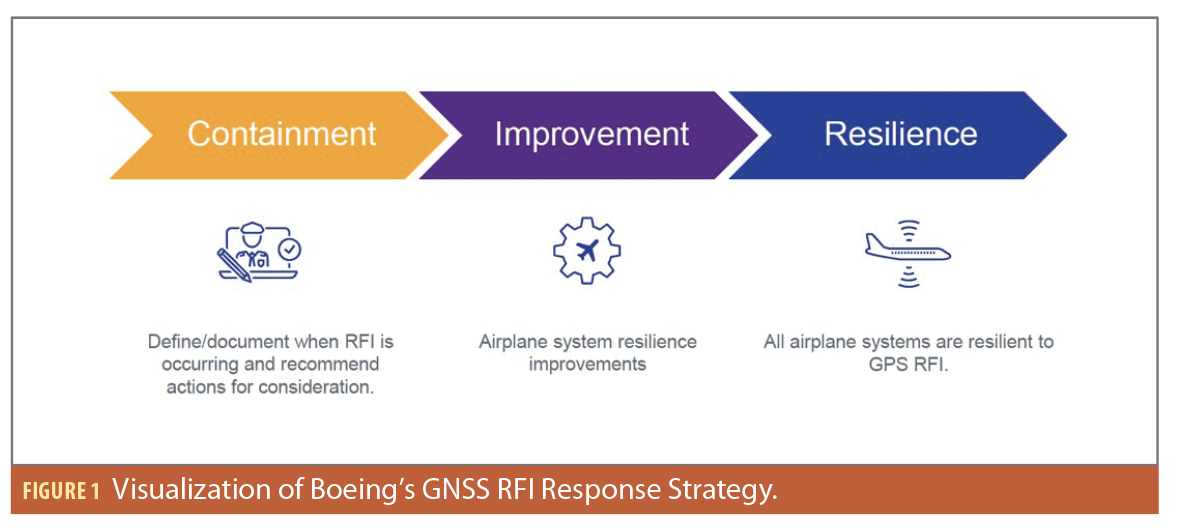
Global involvement from regulators, industries and original equipment manufacturers are needed to achieve GNSS RFI resiliency. Boeing Commercial Airplanes’ comprehensive strategy to identify and mitigate issues related to GNSS RFI is illustrated in Figure 1. The strategy is organized into three major phases: Containment, Improvement and Resilience. Figure 1 may imply these phases are sequential, however, they should more accurately be understood as work streams that happen in parallel. Boeing is working on all three phases at once, however, results from each phase feeds the work of subsequent phases.
Here’s what each phase entails:
Containment: The containment phase focuses on fully understanding the impacts of RFI and doing whatever can be done expeditiously to help Boeing customers deal with GNSS RFI.
Boeing has worked closely with operators to collect data related to GNSS RFI and to share information and recommendations for flight and maintenance crews in a variety of forums. A crucial piece of this collaboration is the release of Flight Operations Technical Bulletins (FOTBs) for the various Boeing models. These FOTBs detail the expected flight deck effects and recommended crew mitigations for GPS and GPS user systems across various Boeing aircraft models.
Initially, Boeing analyzed reports of operator experiences to understand the kinds of RFI events seen in the field. Early on, it was determined manual reporting of RFI events would not be efficient or effective because of the overwhelming occurrence rate of GNSS RFI and potential data inconsistencies. So, Boeing developed and released software that automatically gathers data on adverse GPS events and creates the automated GEM reports, which come from the Aircraft Condition Monitoring System (ACMS) or Aircraft Condition Monitoring Function (ACMF), depending on airplane models.
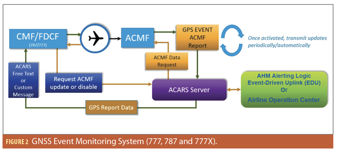
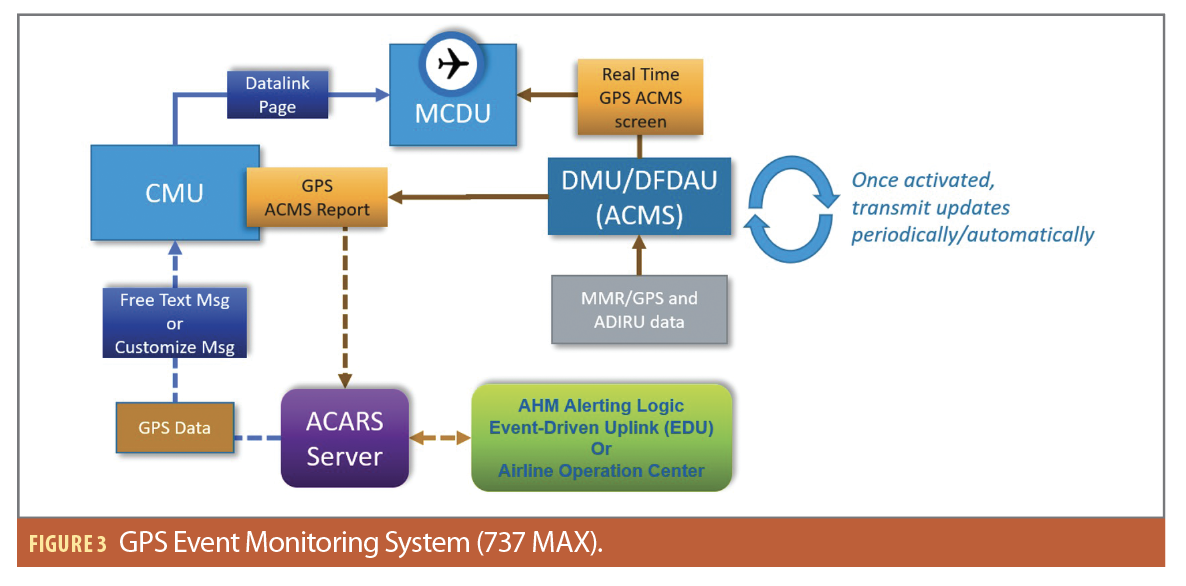
These reports are generated via user-modifiable software inside the aircraft maintenance systems. The software algorithms include robust logic for detecting adverse GPS events and informing operators via datalink messages sent directly to the airlines. These datalink messages are also routed to Boeing, where they are accumulated into a database for further analysis. The GEM report data can also (at the discretion of the operator) be sent/uplinked to the flight deck (as a COMM message) to provide the aircrew situational awareness (Figures 4 and 5). GEM data generation and display requires existing airborne and ground equipment, referred to as the GEM System in Figures 2 and 3.
Boeing uses this data to understand trends, identify zones of high interference activity, and analyze avionics system performance. This information is shared regularly with operators. The data from GEM helps Boeing identify which types of events should be a priority to address in the Improvement and Resilience phases. The data can be monitored over time to verify predicted performance improvements.
Improvement: In this phase, Boeing identifies, specifies, implements and fields actual changes to airplane equipment to mitigate the operational impacts of GNSS RFI. Using reports and data provided by its operators, in conjunction with GEM data, Boeing conducts root cause investigations to identify possible engineering changes that will improve airplane system resilience. For example, Boeing is working on certifying new multi-mode receiver (MMR) software updates on its airplanes to make them more resilient to spoofing. These enhancements to MMR resilience against GNSS RFI will prevent erroneous GNSS data from impacting downstream GNSS user systems, enhancing performance. Additionally, Boeing has completed root cause investigations for Enhanced Ground Proximity Warning Systems (EGPWS) issues due to GNSS RFI with the system supplier and is working on certifying new changes on the EGPWS parts to be made available to Boeing operators to retrofit their fleets.
Throughout the Improvement phase, the GEM system validates that the changes implemented are delivering the expected improvement in performance in the presence of GNSS RFI.
Resilience: New functionality is added to airplanes in this phase that makes them more resilient to GNSS RFI. Boeing is conducting a comprehensive review of its design requirements and philosophy for systems that use GPS in light of the current challenges associated with GNSS RFI. Boeing continues to invest in interference-resistant avionics solutions, including next-generation dual-frequency multi-constellation MMRs that may incorporate signal authentication capability and Controlled Reception Pattern Antennas (CRPAs).
The schedule and availability of these solutions is paced by standards development. When standards are mature, Boeing intends to engage with suppliers, operators and industry experts to develop these new solutions for GNSS RFI. In addition, Boeing is studying Alternative or Complementary PNT systems that might be deployed to make navigation capabilities more resilient at the airplane level. The ultimate goal of the resilience phase is to make GNSS RFI a non-issue with respect to normal airline operations.
The GEM System
The GEM System illustrated in Figure 2 is representative of 777, 787 and 777X.
The GEM system consists of onboard ACMF and a Communication function and ground system to move and display GEM data. Starting at ACMF detection of disagreement or abnormality in the GPS data, ACMF reports the event via ACARS downlink. On the ground, the Airline Operation Center or Boeing Airplane Health Management (AHM) services receives the GEM report, then decodes and stores the data for analysis. They also automate the uplink messaging with GEM data to notify aircrews. Back on board, the Flight Deck Communication Function (FDCF) or Communication Management Function (CMF) receives the GEM data uplink message, decodes it and displays it to aircrews. The aircrews can view the GEM data and request a manual update of fresh GEM data on-demand instead of waiting for the next event.
GEM report logic in ACMF is designed to automatically detect GPS position and satellite data that is inconsistent between multiple GPS sources or inconsistent with inertial and air data. The monitor logic is also designed to detect GPS date and time shifts after the start of the flight based on the reference date and time snapshot at the beginning of the flight and independently count forward. The report is generated with the GPS DATA DISAGREE flag set to YES if any of the known symptoms below are detected:
• DATE SHIFT. The date components of the GPS receiver timestamp are compared to uncorrupted reference values to determine if deviation criteria are met to trigger a date shift.
• TIME SHIFT. The time components of the GPS receiver timestamp are compared to uncorrupted reference values to determine if deviation criteria are met to trigger a time shift.
• POSITION SHIFT OR INVALID. The latitude and longitude from a GPS receiver are compared to the uncorrupted inertial position data to determine if deviation criteria are met to trigger a position shift.
• ALTITUDE SHIFT OR INVALID. The altitude from a GPS receiver is compared to the uncorrupted barometric altitude data to determine if deviation criteria are met to trigger an altitude shift.
• VFOM LARGE OR INVALID. The behavior of the Vertical Figure of Merit from a GPS receiver is analyzed to determine if it becomes too large or unstable, in which case this event flag is set.
• SATELLITES TRACKED LOW. The number of satellites tracked from a GPS receiver is analyzed to determine if enough satellites are present to compute a navigation solution, if not this event flag is set.
• NOT IN NAV MODE. The operational mode from a GPS receiver is analyzed to determine if the receiver is operating in one of several navigation modes or another mode. If the operational mode is not one of the navigation modes, this event flag is set.
The GEM System illustrated in Figure 3 is representative of the 737 MAX. GEM data is displayed in real-time with GPS DATA DISAGREE flags on the Multi-functional Control Display Unit (MCDU) under the ACMS sub-menu, and reports are downlinked. Ground operations can relay the message to notify aircrew of the event. That message is also displayed on MCDU under the datalink sub-menu. Because all data ends up on the MCDU, the uplink notification message can simply state the event: GPS RFI ENTRY/CONTINUE/RECOVERY. If aircrews need to view the detailed data, they can access GEM data from the ACMS sub-menu. Note aircrews do not need to send a request to refresh GEM data because the data is updating in real-time.
GEM Reporting Frequency
Once an event is detected (the first among all other events), a report is generated. This first report is known as the GPS RFI Entry report, indicating the airplane is experiencing a possible RFI related event. In this case, the GPS DATA DISAGREE flag is set to YES.
If one or more events are active after the Entry report, the periodic report is generated every 20 minutes for the first hour and then followed by a report every one hour after the first hour. These reports are known as GPS RFI Continue reports. In this case, the GPS DATA DISAGREE flag remains set to YES.
Once all events are recovered (all events are no longer active for 20 minutes), the GPS RFI Recovery report is generated to indicate GPS data are back to normal and the aircraft has possibly exited the RFI region. In this case, the GPS DATA DISAGREE flag is reset to NO to reflect recovery from all symptoms.
Note: All timers might be customized or programmed to be modifiable parameters based on airline needs.
GEM Display to Aircrews
Optionally, flight operations at the airlines can decide if they want to receive the GEM report data update in the communication function of the airplane. If airlines choose to do this, an ACARS or AHM engineer will script the capability to automatically detect the GEM report downlink and relay the data to aircrews via an ACARS uplink message.
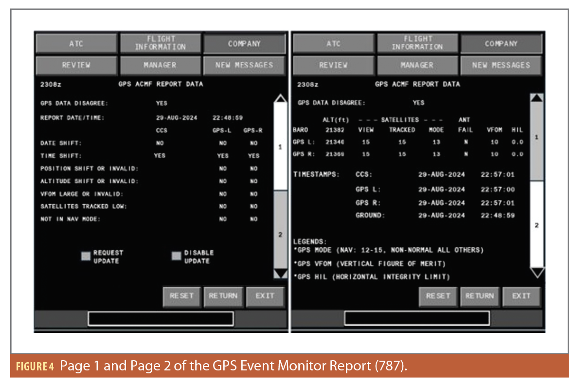
Once the communication function receives the message, aircrews will receive a notification via a COMM reminder on the forward display and an aural cue in the cockpit. GEM report data uplink produces two pages of information for the aircrews. The first page provides the top level GPS DATA DISAGREE flag, the seven associated symptom flags, and when the report was generated. The page also has the following control actions for pilots:
The REQUEST UPDATE, when commanded by the SEND action, will downlink the request to ground. Ground operation relays the request by doing an uplink to request ACMF to generate a report on demand. Once ACMF generates the new report, the data path repeats itself as described in the GEM System in Figure 2.
The DISABLE UPDATE, when commanded by the SEND action, will tell ground operation to stop the automatic relay of GEM data uplink until the end of the flight or until aircrews enable the feature again.
A typical GEM data display to aircrews is illustrated in Figure 4. This example is from the 787 model, and shows the TIME SHIFT symptom has occurred on both GPS receivers.
The second page of a GEM report, illustrated in Figure 4, provides situational awareness in the form of raw data from GPS used to generate the GPS event YES/NO indications, as well as additional information. Each of the items on the second page are described here:
GPS DATA DISAGREE. This is the same indicator as Page 1.
• ALT (ft) The BARO, GPS-L and GPS-R altitudes are shown for reference. The barometric altitude is sourced from air data and is expected to differ from GPS altitudes within a specified tolerance.
SATELLITES. The VIEW column indicates the number of satellites that should be in view. Large differences could be an indication of spoofing impacting one GPS receiver and not the other. A zero in this location could indicate a reset and acquisition mode are in progress for that receiver.
• The TRACKED column indicates the number of satellites acquired and tracked by the corresponding GPS receiver. The numbers can vary from one receiver to the other, although large differences could indicate interference on one receiver and different impacts on the other receiver. Zero tracked satellites indicates jamming or a receiver in acquisition mode attempting to regain navigation mode.
• The MODE column indicates the navigation mode of the receiver. Mode 3 is a navigation mode. All other modes are alternate or non-normal modes that should not occur during flight.
• The ANT FAIL indicator is set to Y for YES when the corresponding GPS receiver is not operational due to a detected antenna failure. This antenna fail indication can help distinguish an antenna fault from interference.
• VFOM is for situational awareness and can help aid in understanding Page 1 information.
• HIL indicates the Horizontal Integrity Limit (HIL) and is for situational awareness. This parameter is needed for RNP/RNAV and ADS-B Out.
TIMESTAMPS. These timestamps are provided for awareness:
• On most airplane models, the time is based on GPS when valid, but may coast after loss of GPS. Airplane time can be erroneous if GPS time is erroneous.
• GPS L or R time is invalid during interference or potentially erroneous during spoofing, although some receivers may invalidate GPS outputs during spoofing. Due to system display limitations, invalid GPS date and time always displays as “11-NOV-2011 11:11:11.”
• GROUND time is sent from the ground in the COMM message. This time is independent from airplane or GPS time and is used as a comparison against airplane and GPS times.
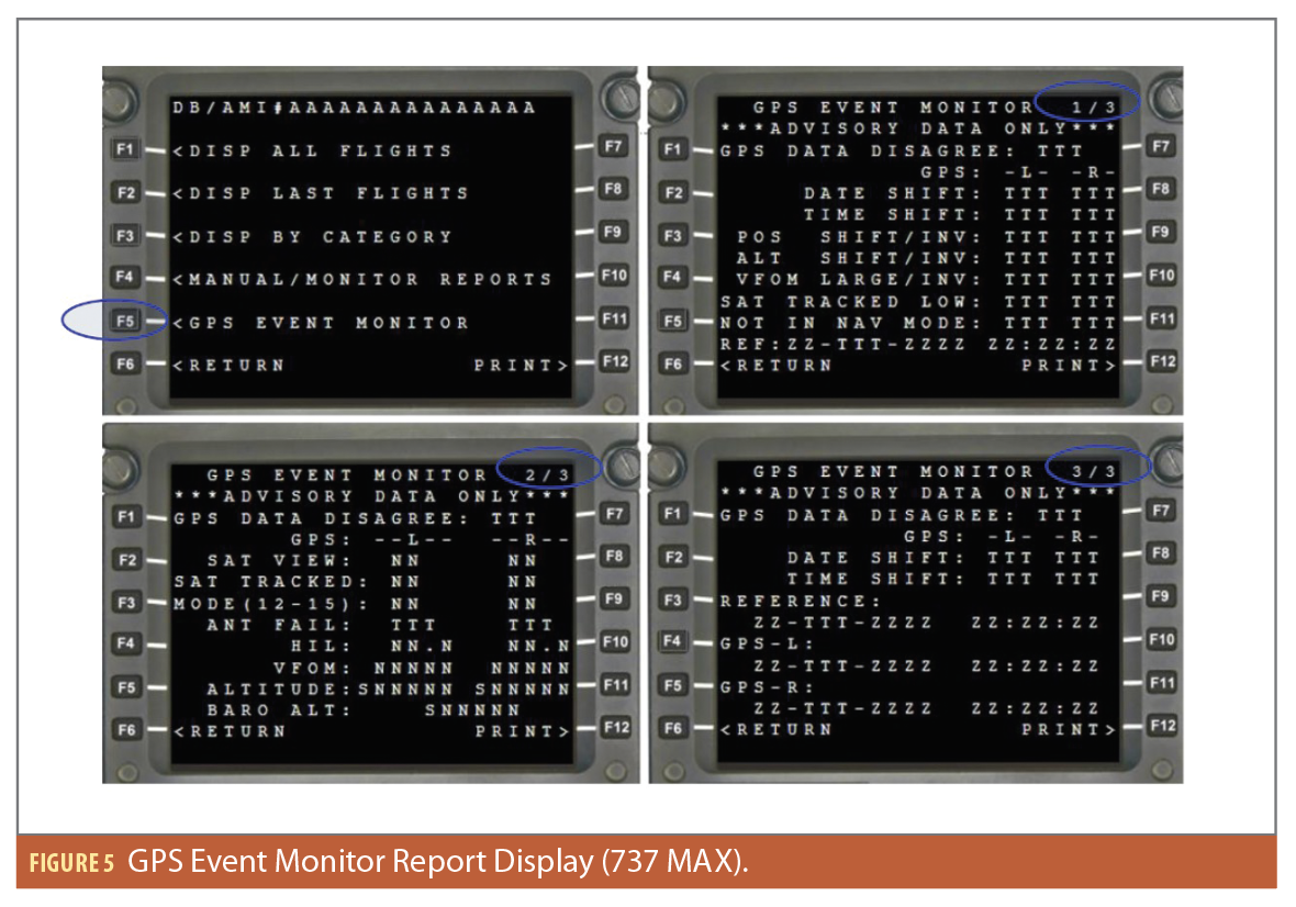
The ACMS GEM data on the 737 MAX shows similar content as described but are formatted to fit MCDU limit screen size (Figure 5).
GEM Report Use by Airlines and Boeing
The GEM report has been deployed on the 777 aircraft since June 2024, on the 787 aircraft since April 2025, and on the 737 MAX aircraft since April 2026. Service letters are published with a suggested monitoring algorithm that would allow operators of legacy models like the 737(NG and Classic), 747, 757 and 767 to develop and install a version of the GEM report on those models. During the time period of data collection, Boeing has received over 1.3 million GEM reports from over 1,000 unique aircraft in service across 52 different global operators.
Insights from GEM Data Analytics
The information provided by the GEM reports serves as an enabler for useful analytics related to GNSS RFI. First, the symptom flags and airplane inertial position, coupled with the time history of reports for a given flight leg, allow Boeing to determine where an airplane was located when a GPS RFI symptom first occurred. This information, when combined with full flight position history from sources such as ADS-B data, allows Boeing to create Flight Information Region (FIR) heat maps based on the occurrence rate of specific GPS RFI symptoms or symptom classes.
For the purposes of analysis, the seven GEM data symptom types are placed into three main symptom classes: GPS Loss, Position Error and Date/Time Error. All symptom classes indicate a set of behaviors observed by the GEM report at the GPS receiver level.
GPS Loss indicates the presence of jamming symptoms in the GNSS receiver(s) as indicated by:
• Satellites Tracked Low Symptom Flags
• Receiver Not in Navigation Mode Symptom Flags
Position Error indicates the presence of spoofing symptoms with GNSS receiver(s) horizontal and vertical position solutions as indicated by:
• Lateral Position Shift or Invalid Lateral Position Symptom Flags
• Altitude Shift or Invalid Altitude Symptom Flags
• VFOM Large or Invalid Symptom Flags
Date/Time Error. The presence of spoofing symptoms with GNSS receiver(s) date and time solutions as indicated by:
• Date Shift or Invalid Date Symptom Flags
• Time Shift or Invalid Time Symptom Flags
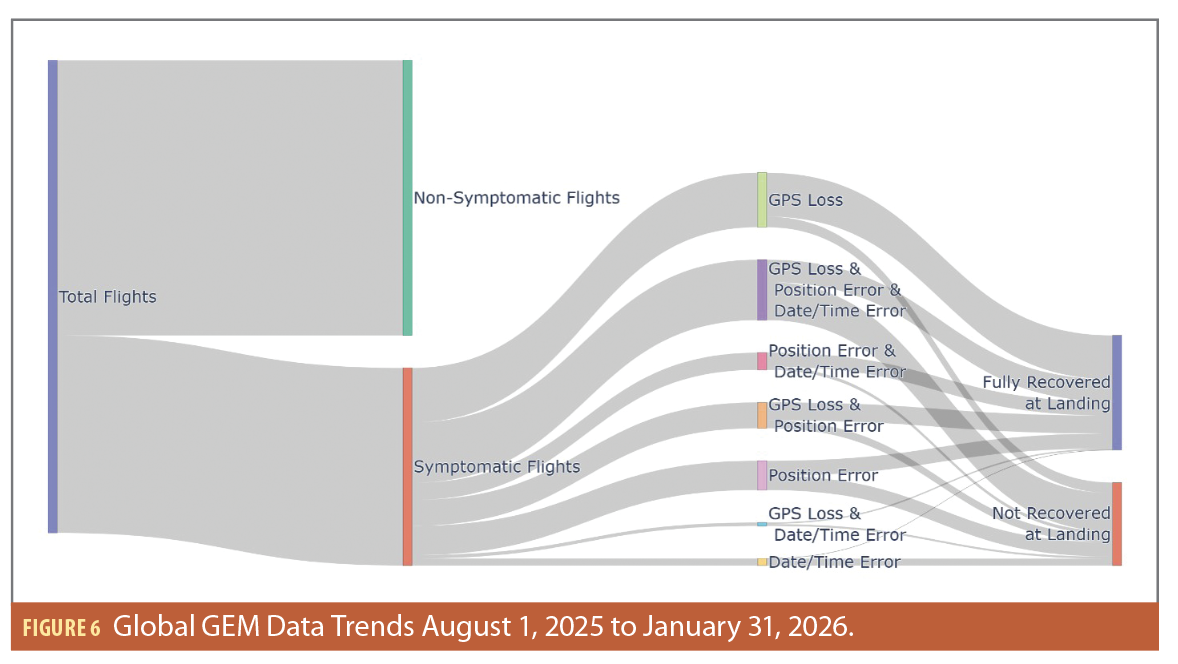
These symptom classes are not mutually exclusive; many flights experience symptoms from all three symptom classes. Figure 6 provides details regarding symptom class coincidence and associated recovery trends on flight legs flown by 777 and 787 aircraft equipped with the GEM report between August 1, 2025, and January 31, 2026.
Figure 6 provides a visual breakdown of symptom class coincidence and the associated recovery outcomes. A few observations can be made based on this visual. First, the GPS Loss symptom class is the most common symptom class present across all combinations, followed by Position Error and then Date/Time Error. Second, Date/Time Error symptoms most commonly occur when a flight leg also experiences Position Error and/or GPS Loss symptoms. Finally, the recovery outcome of a flight leg can vary drastically based on the combination of symptom classes that a flight leg experiences.
During the period of data collection, approximately 31% of flights experienced GPS Loss, Position Error and Date/Time Error symptoms. Only 37% of the flight legs that experienced symptoms from all three classes landed with both GPS receivers fully recovered. The second most common outcome is a flight leg only experiencing symptoms from the GPS Loss class. This group represents approximately 28% of symptomatic flights, with nearly 81% of flight legs experiencing this symptom combination indicating both receivers fully recover before landing. The substantial difference in recovery outcomes highlights the influence of the symptom class combination experienced by a flight leg on recovery outcomes.
Within the GEM dataset, Boeing tracks the initialization of a symptom on a flight leg as well as any reoccurrence after a symptom’s recovery criteria are met. Both the initializations and reoccurrence contribute to the numerator of the occurrence rate calculation within a given FIR. The denominator in the occurrence rate calculation is determined by the total number of flights equipped with the GEM report that flew through the FIR in the period of interest.
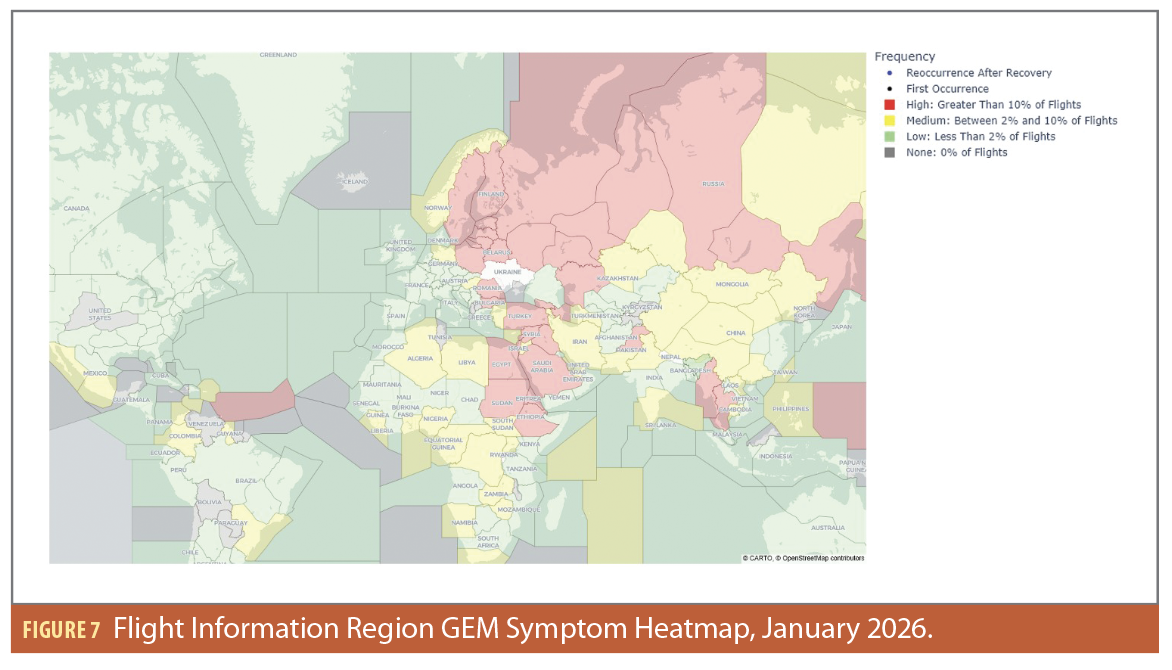
Figure 7 shows the global FIR heat map for all GEM symptom occurrences. To create this map, a global OR logical operation is used in the FIR occurrence rate calculation, meaning if a flight leg has either an initialization or reoccurrence of any GEM report symptom in the FIR, it will contribute to the overall occurrence rate of interference symptoms within the FIR.
The January 2026 data shown in Figure 7 shows substantial interference activity in Russia, Eastern Europe, the Middle East region, the Eastern Africa region, the Black Sea region, the
region surrounding Venezuela, and the Southeast Asia region.
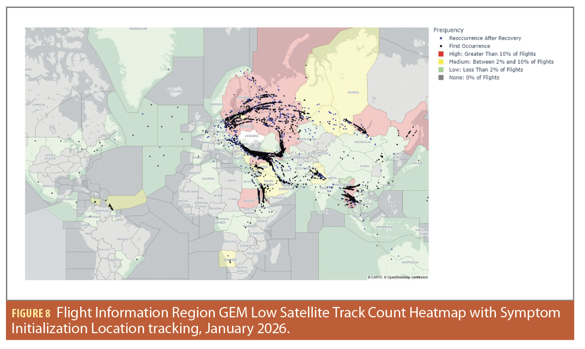
In addition to the All Symptom type heat map, Boeing also produces heat maps and regional datasets to compare individual symptom occurrence rates. An example of this is shown for the low satellite track count symptom in Figure 8.
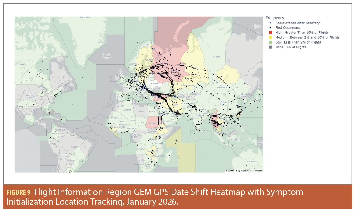
For the individual symptom maps, in addition to color coding FIRs by their symptom occurrence rate, the inertial positions of the aircraft at the time of symptom initialization (black dots) or reoccurrences (blue dots) are also mapped. The inertial position is from an uncorrupted inertial solution that is independent of GNSS information. This provides important contextual information as some FIRs are large and interference may only impact a portion of the airspace. The initialization and reoccurrence information provide a good visualization of where interference has historically occurred within a given FIR.
Another example of a symptom specific heat map is given in Figure 9. This figure shows the initialization and reoccurrences of the Date Shift symptom. Date shifts are believed to only occur as a result of specific types of spoofing attacks. Therefore, comparing Figures 8 and 9 can give some insight into the relative frequency of jamming that results in a denial of service and spoofing attacks that result in a Date Shift.
The ever-growing database of GEM reports can be analyzed in many ways, providing insights into what is really going on with Boeing airplanes in the field. Boeing can sort the data according to airplane model, airline, receiver manufacturer, and even filter by specific part numbers. This has proven to be a valuable tool as we continue to work with customers on root cause analyses when new types of GNSS RFI are experienced.
Unfortunately, the threats to GNSS evolve over time and spoofing attacks appear to be getting more sophisticated. This analytical tool can help as we respond to changes in the threat landscape. Furthermore, we can add additional logic to GEM reporting to detect new symptoms as they are identified. Probably most valuable of all, we can compare the performance of specific receivers with different software uploads to verify software improvements are indeed effective at addressing the issues they were intended to mitigate.
Future GNSS receiver versions are expected to have richer jamming and spoofing detection reporting at the receiver level. When these are available, Boeing will incorporate that information in the triggering algorithms and GEM reports as appropriate.
Heat maps such as those shown in Figures 7, 8 and 9 are not uncommon. Many organizations have websites that provide similar heat maps (see example at gpsjam.org). These can be very useful tools to see general trends in GNSS RFI. However, they have limitations in that the GNSS RFI detection is usually done by inference based on ADS-B reporting. The GEM system collects actual events reported by airplanes and does not rely on inference of jamming and/or spoofing based on ADS-B observations.
Other systems based on ADS-B reports may have some ability to sort data according to aircraft, but generally don’t have the visibility of receiver types or even receiver part numbers. The GEM data and associated maps also provide a greater level of symptom specificity than what is provided by ADS-B only data solutions.
Future Work
As both the global GNSS interference environment and GNSS receivers continue to evolve, Boeing will continue to evolve the GEM report system with the speed of relevance. As new symptoms or behaviors resulting from GNSS interference are identified, they will be added to future revisions of the GEM report. GEM report data will also continue to be leveraged to assess GNSS receiver performance as new technologies are deployed to the in-service fleet. This analysis will provide valuable feedback to ensure new solutions continue to exhibit the performance improvements in GNSS interference environments the design intended.
Authors
Nathaniel Thomas is a Systems Engineer at the Boeing Company. During Boeing’s ongoing response to GNSS Interference, he has served as the primary focal for data analytics activities related to GNSS Interference. He holds a B.S. and M.S. in Aeronautical and Astronautical Engineering from Purdue University.
Tim Murphy is a Senior Technical Fellow with the Boeing Company where he works on communication, navigation, surveillance (CNS) and Spectrum issues related to Air Traffic Management. Tim has more than 43 years of experience in the field of radio CNS systems for civil aviation. The current focus of his work is avionics for new airplane product development, autonomy and next generation CNS technologies to support air traffic management. Tim is very active in the development of domestic and international standards for CNS technologies and Spectrum for use by commercial aviation.
Christopher Nguyen is a Lead Electronic Systems Design & Analysis Engineer at the Boeing Company. He leads the development, testing and release of Airline Modifiable Information (AMI) software, including reports used in the GPS Radio Frequency Interference response. He has 21 years of software development experience at Boeing Commercial and Boeing Defense businesses. He earned his B.S in Electrical and Computer Engineering from Cal Poly Pomona, M.Engr in Software Engineering and Management from the University of Illinois, Chicago.
Colin Wilkins is a functional manager in Boeing Avionics where he leads a team that designs and integrates Radio Navigation equipment, including GPS equipment, for all Boeing production models. He and his team lead the development of the GEM logic and how to use the analytics to inform future equipment and aircraft design.