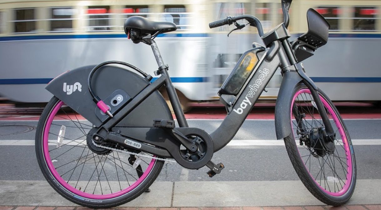
eMobility services that provide on-demand eBikes and eScooters rentals are fast growing alternatives to traditional transportation modalities. As they are affordable, convenient, and very green, eMobility services will continue to grow in popularity. This article presents some of the challenges and useful solutions to accurately track eBike and eScooter location in the real world.
At the heart of the eMobility experience is precise location of the bike or scooter. Accurate location is not only about quickly finding a bike on demand, but location accuracy also directly impacts the cost to operate the fleet. As shown in a 2019 McKinsey & Company study, Charging, which includes pick-up and return of the bike or scooter, is an important cost. Having a paid service team member hunting around to find a missing bike is very expensive (see Figure 1).

Besides locating vehicles for riding, swapping batteries and servicing, parking compliance also requires excellent location accuracy. There is a general trend towards light-weight stations or parking corrals that are non-electrical. Bikes and scooters rely completely on the GNSS module for localization. Every meter in improved accuracy counts here to determine if a vehicle was parked in a light-weight station or a dedicated parking spot painted on the side of a street. City fines for improper parking can be a significant cost for micro-mobility companies.
GNSS Alone Does Not Work
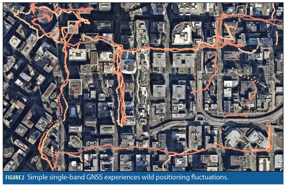
On first thought, adding a GNSS receiver to the eBike should be a simple solution to locate the eBike. However, urban cities are not friendly to most GNSS receivers today. How bad is it? 100-meter errors are not uncommon in the real world. Data collected and shown in Figure 2, downtown San Francisco, shows visually just how significant the location variation is when riding urban streets.
There are three potential ways to improve location accuracy:
• Dual-band GNSS receivers (L1+L5 or L1+L2)
• Dead-reckoning with an inertial measurement unit (IMU)
• GNSS Corrections such as real-time kinematic (RTK)
High-end navigation systems have utilized these techniques for years, so the ideas are not new in a technological sense. However, implementing these techniques for less than $10 and at very low-power consumption requires the newest generation of technology.
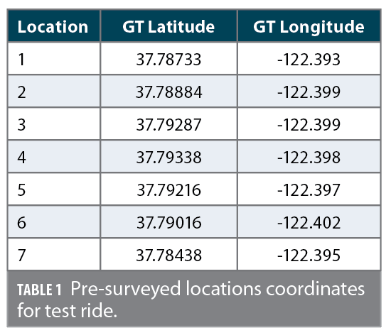
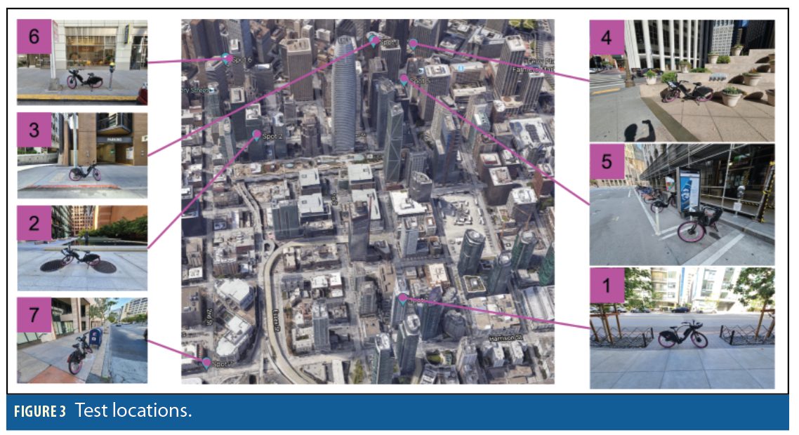
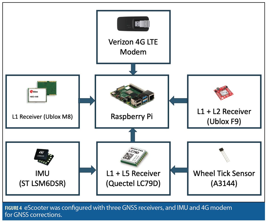
To test all these combinations, an eScooter was configured with the hardware shown below and ridden in downtown San Francisco to test the various combinations of L1, L1+L2, and L1+L5. Lyft determined a set of seven pre-surveyed and easily identifiable test locations that are representative of real-world use. Figure 3 gives pictures of the seven locations and Table 1 lists their latitudes and longitudes.
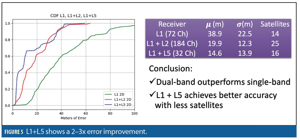
Dual-band receivers that utilize newer L5 (GPS, QZSS), E5 (Galileo), and B3 (Beidou) satellite signals can reduce multipath errors. The GPS L5 signal and the international flavors feature wider signal bandwidth that is less susceptible to multipath-induced errors. There are also dual-band receivers that utilize L1 and the L2C signals that are available as well, and the benefit of the L2C band is that of full constellation and maturity. Figure 5 shows the improvement in accuracy obtained by migrating to a dual-band receiver in the same test conditions as the data above.
The chart is important because it shows that even when tracking fewer satellites (which has the benefit of lower-power consumption), the accuracy of an L1+L5 receiver shows significant improvement over alternatives.
Dead Reckoning (DR) and IMU Assist
However, there are still downtown cases where even dual-band GNSS is quite poor due to reduced satellite count and heavy multipath. These are the cases where dead-reckoning with an IMU can really help. Dead-reckoning and sensor fusion on an eMobility platform works by tracking the vehicle with accelerometers, gyroscopes, and a wheel tick sensor. Dead reckoning can be used when there are no satellites, such as determining the location of an eBike in an underground parking garage, and it can also be used as to filter out wild location’s fluctuations caused by multipath in narrow downtown streets.
To analyze the drift performance of dead-reckoning, a simplified model considering the initial heading error, the odometer scale factor error, and the gyro drift rate is considered. Realistic figures of merit from low-cost hardware are:
• θe Initial Heading Error < 0.8°
• Ωb Gyro Bias < 36°/Hr (0.01 °/s)
• Le Wheel Tick Error < 1%
Today’s consumer MEMS-based IMU chips may offer better gyro bias instability at constant temperature. In the real-world, 36°/Hr is a pretty typical level of drift. Initial heading error is driven by the GNSS velocity accuracy, and the 0.8 degree accuracy is typical at 3–5m/s speed in decent sky conditions with 8 or more satellites. Finally, the wheel tick error of 1% or better is easy to achieve with a simple Hall-effect sensor. More precision can be achieved with an encoder or a hall sensor set up with multiple ticks per revolution. Initial heading error and wheel tick error both lead to linear error growth, whereas the gyro bias leads to faster quadratic error growth.
• Initial Heading v θe t
• Z-Axis Gyro Drift v Ωb t2
• Wheel Tick Error v Le t
where v is velocity and t is time of GNSS loss.
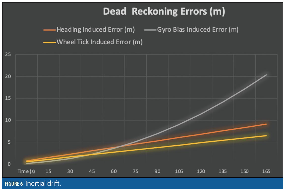
Applying these assumptions, we can see that position of a few meters is maintained for up to a minute in full GNSS loss, and that a longer outage of nearly three minutes will start to show more significant drift driven by the gyro-bias which leads to additional heading error growth (Figure 6).
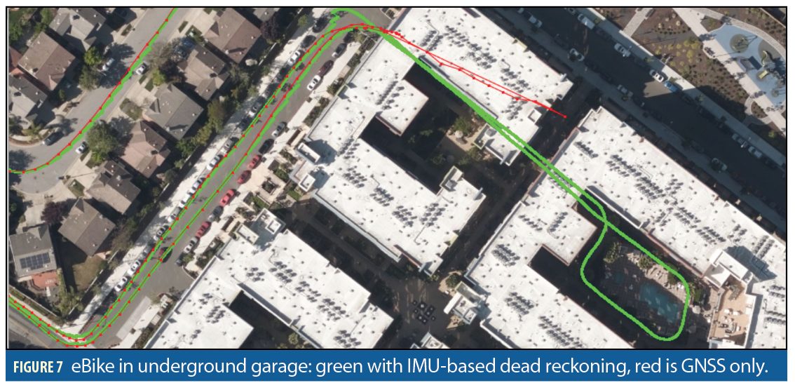
Figure 7 shows an example test where an eBike is ridden into and out of an underground apartment parking garage. As can be seen when exiting the parking garage after approximately two minutes, the position correction is on the order of 2 meters.
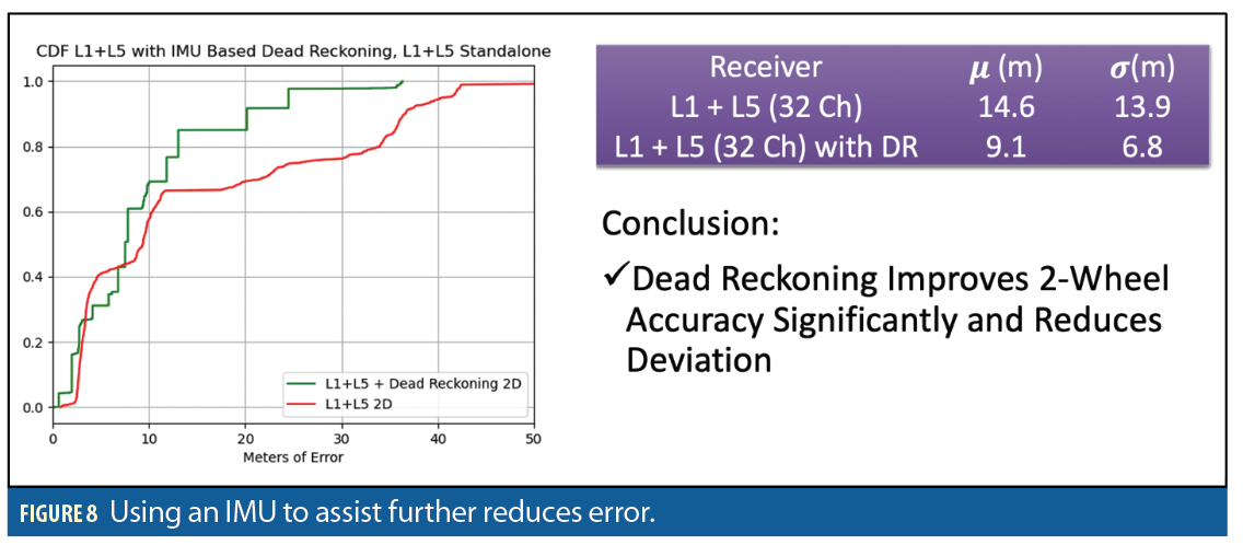
In downtown environments, dead-reckoning can filter out and reject noisy GNSS measurements keeping the solution more stable and consistent. Figure 8 shows the impact of dead-reckoning on the solution performance in the same locations.
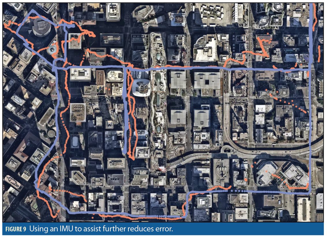
The improvement in trajectory of the combined dual-band L1+L5 and IMU dead reckoning solution is also very clear in Figure 9.
GNSS Corrections and RTK
GNSS satellite signals are subject to well understood errors (clock, orbit, and atmospheric) that fundamentally limit stand-alone position accuracy to around one meter best case. However, using corrections from a local GNSS base station or a network of GNSS base stations, these errors can be reduced to centimeter level with RTK. There are potential benefits of RTK in two use cases:
• Downtown urban canyon
• Accurate geofencing for applications such as parking compliance
RTK however, cannot reduce mult-path errors, so don’t expect centimeter precision in downtown urban canyon condition. In our testing, we saw a 30% accuracy improvement with the use of RTK in downtown environments. The improvement is most significant in locations with better sky visibility.
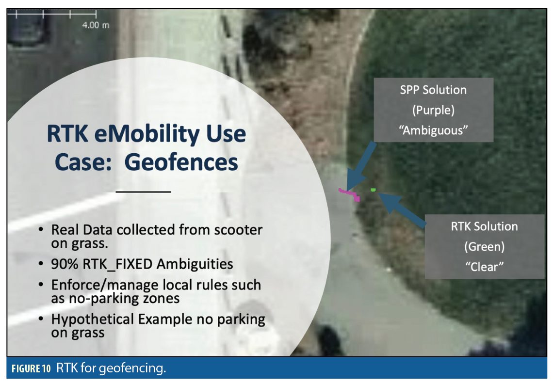
Accurate geofencing is an excellent potential use of RTK in eMobility applications. Take for example a hypothetical case where a city has issued local regulations that restrict parking to sidewalks and street locations. In Figure 10, an eScooter was parked in the grass near the edge of the sidewalk. The RTK solution provided a clear unambiguous fix.
The non-RTK, SPP (standard point positioning) is ambiguous. This might result in a city official or citizen raising an issue harming the reputation of the eMobility service provider.
The RTK solution is clear. The eMobility company can arrange for the parked bike to be moved onto the sidewalk and notify the user of the conduct violation.
Conclusions
eMobility is growing in popularity, and this service requires accurate location and positioning technologies to meet consumer demand, reduce maintenance operating costs, and comply with new local regulations. Dual-band L1+L5 receivers with integrated dead-reckoning and RTK offer effective solutions to improve accuracy by up to an order of magnitude over a traditional L1 only receiver.
Manufacturers
Low-cost multi-band multi-constellation GNSS receivers have emerged recently from Synaptics (previously Broadcom), ST Microelectronics, and MTK/Aihora. These chipsets are not readily available off-the-shelf as components; however, Quectel offers two convenient modules LC29 and LC79 utilizing the Synaptics silicon. Quectel also offers the dual-band LG69 that utilizes ST Microelectronic’s TeseoV (ASIL-B) and is more geared to safety-critical 4-wheel applications. MTK/Aihora’s AG3335 dual-band silicon is not readily available as a module yet, but it will likely start to appear more frequently in the second half of 2021.
Authors

Mike Horton was founder and CEO of Crossbow Technology, focused on tracking devices and inertial navigation systems for logistics/asset tracking and military applications; acquired by Moog, where he continued as an executive. He was then CTO of ACEINNA, responsible a low-cost and open-source hardware/software platform, The OpenIMU platform, for inertial navigation and GNSS/INS precise positioning in a wide range of autonomous applications including cars, drones and agricultural equipment. He is currently an independent consultant and investor. He holds a Masters degree in electrical engineering from the University of California.

Jens Windau is a hardware data scientist for bikes and scooters at Lyft. He is also founder and CEO of AIORobotics and WinRobotics. He has a Ph.D. in computer science from the University of Southern California.
![Trimble_BD9250_right v03[17]](https://insidegnss.com/wp-content/uploads/2022/05/Trimble_BD9250_right-v0317-150x150.jpg "Trimble Introduces High-Accuracy OEM GNSS<br>Receiver Module for Industrial Autonomy Applications")


