An open source implementation of a Global Navigation Satellite System (GNSS) software receiver targeting the Globalnaya Navigatsionnaya Sputnikovaya Sistema (GLONASS) L1 C/A signal addition is presented.
The signal composition and general architecture of the proposed software receiver implementation are provided along with detailed descriptions of the main signal processing algorithms involved in acquisition, tracking, and telemetry decoding of the navigation signal. Connections to external software by means of traditional format output standards are also presented and validated with real-life signals.
The transmission of new radio navigation signals in a dedicated band has revolutionized the GNSS industry by allowing for crosscompatibility and reduced expenses in receiver design. The concept started with the transmission of the Global Positioning System (GPS) L1 C/A signal, which soon after became the gold standard of radio navigation. GLONASS satellites followed and the constellation reached maturity during the Soviet Union era, but degraded after its collapse. The Galileo constellation finally cemented this idea with the addition of the E1 open service signals. Such efforts prepared the field for international collaboration and signal design around the concept of multi-constellation receiver designs.
The Government of the Russian Federation approved by its Decree No. 587 of 20 August 2001, a budget of 347 billion ruble (US $11.81 billion), running through 2020 by which a federal task program will restore and modernize the GLONASS constellation. The program aims at improving the space, groundbased, and user equipment segments of the system. By 2010, the constellation reached full coverage in Russia and in 2011 full operational capability when the full orbital constellation of 24 satellites was achieved. Aiming to provide better accuracy, multi-path resistance, and especially, greater interoperability with GPS, Galileo, and other GNSS, new GLONASS-K satellites will transmit Code Division Multiple Access (CDMA) signals in addition to the system’s traditional Frequency Division Multiple Access (FDMA) signals. GLONASS system restoration is almost completed and the latest updates seem to indicate that the program is on track and has enough budget to complete its modernization in the future (see Additional Resources, I. Revnivykh). The new modernized system will ensure that GLONASS coherent FDMA and CDMA navigation signal sets will satisfy a wide range of user requirements, from ordinary navigation to high-precision applications.
With the international community moving in this direction, it is more common nowadays to see receiver development focused on CDMA techniques targeting single bands and simplifying the receiver design. Given all this, it is worth asking: Is there benefit in GLONASS FDMA signal processing? What are the advantages of a navigation system processing GLONASS FDMA signals?
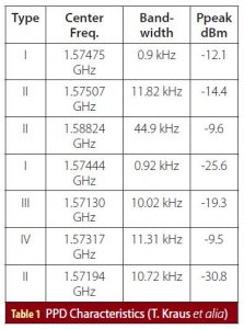
Previous research highlights feasibility and effectiveness of cheap jammers on radio navigation signals (T. Kraus et alia; A. D. Fonzo et alia). It can be speculated then that a system moving toward a single band navigation system by means of CDMA exploitation is also extremely susceptible to commercial off-the-shelf jammers and Personal Privacy Devices (PPD). An analysis of commercial offthe-shelf units and PPDs showed how these devices can turn a wide range of CDMA signals completely unusable in their presence (T. Kraus et alia). Interestingly enough, of the seven devices studied, only 10% were capable of blocking the bands where GLONASS and its frequency channels operate (Tables 1 and 2). Taking advantage of the processing of GLONASS FDMA signals is not a direct anti-jamming or anti-spoofing technique, but use of these signals does make it harder to harm the system.
Another interesting case was the recently reported episodes of GPS spoofing happening in the Black Sea (S. Goff). Given the resources available, receivers can no longer simply rely on one single constellation or the other. The future lies in the design of receivers capable of mixing solutions from multiple constellations in a wide range of frequencies. Maybe the presence of a GLONASS capable receiver would have avoided the spoofing by allowing the system to eliminate the compromised GPS measurements and perform navigation with the aid of the GLONASS FDMA signals, assuming of course that the latest signals were not also
spoofed in the area during those episodes.
This work presents a new signal addition to the Global Navigation Satellite System Software Defined Radio (GNSSSDR) platform, making the receiver more robust and diverse. With the GLONASS L1 C/A signal addition, the GNSS-SDR software receiver is available for a new set of applications based on the use of the GLONASS FDMA signals. Given the points made earlier, it seems that receivers taking advantage of a new signal could be better prepared against malicious attacks of any kind. This work is not of course the first implementation of the GLONASS L1 C/A signal and there are multiple implementations by commercial off-the-shelf receivers that support this signal without major issues. Such commercial receivers come with a high price tag that could be a barrier in low funded applications or studies. Some open source versions also support the GLONASS L1 C/A signal, like GNSSSDRLIB, but its software implementation is limited to only the Windows 64 bits platform, does not takes advantage of the latest Intel Advanced Vector Extensions (AVX), and does not support its exportation to available embedded platforms (T. Suzuki and N. Tubo).
GNSS Software Receivers
Since the advent of the Software Defined Radio (SDR), an increasing number of GNSS software receivers have been developed by members of the navigation community. Typical implementations will use low level programming languages like C or C++ in order to achieve a real time receiver running in a general
purpose computer or an embedded platform. Another design approach implements the receiver in a high level programming language like MATLAB or Python, and develops a software receiver ideal for post-processing applications. Popular and open source implementations include GNSS-SDR, GNSSSDRLIB, and SoftGNSS. GNSS-SDRLIB, mainly developed by Taro Suzuki was developed in C and uses the RTKLib navigation engine for computation of the position solution (T. Suzuki and N. Kubo). The software receiver supports all major constellations and signals providing acquisition, tracking, and pseudorange metrics for post-processing analysis. This software receiver, however, is no longer under active development. On the other hand, softGNSS is a software receiver for post processing analysis developed in MATLAB, source code of the receiver is provided with the book that introduces it (K. Borre et alia), and it provides code for a GPS L1/CA signal receiver. Even though multiple efforts have been directed towards extending the receiver capability with the addition of new signals and features, its MATLAB implementation does not make this software receiver adequate for real time signal processing. Another important contribution to the community comes with the software receiver developed by Thomas Pany and his book on GNSS signal processing (see Additional Resources), which introduces key concepts of GNSS software processing in personal computers and discusses several common techniques that can be used to achieve real time processing. In the author’s opinion, a major contribution of this book was the usage of assembly language to accelerate common operations on GNSS signal processing.
There are also commercially available software receivers for use in the community. The business approach for this concept mostly includes a combination of IP core licensing and/or royalties for its use. The commercial implementations will serve multiple applications such as multipath and spoofing evaluation, ionosphere scintillation, interference monitoring, etc. One such software receiver version is capable of running in real time more than 300 channels in a general purpose computer with an Intel Core i7-7490k processor. The solution also provides a hardware front end for data collection and is integrated with the software receiver provided (see Manufacturers section near the end of this paper). Other options will provide free academic versions (normally introduced with a textbook) (I. Petrovski and T. Tsujii) and will then charge for a professional version of the software, including one which will also have the option of a custom Radio Frequency (RF) front end to interface with the software receiver. The result of years of experimentation with software radios as applied to GNSS technologies is a well-established set of tools for the scientific community with plenty of options to pick from depending on end applications, budgets, and experience in the field of radio navigation.
GNSS-SDR
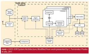
Development of the work presented here was accomplished with GNSS-SDR. This is an open source receiver developed in C++ that uses the GNURadio Application Programming Interface (API) to develop a real time software receiver. The high level of flexibility and re-configurability makes this implementation a very appealing solution to an ever increasing radio navigation signal environment. GNSS-SDR provides an interface to different suitable RF front-ends and implements the entire receiver chain from signal reception up to the navigation solution. Its design allows any kind of customization, including interchangeability of signal sources, signal processing algorithms, interoperability with other systems, and output formats, and offers interfaces to all the intermediate signals, parameters, and variables (C. FernándezPrades et alia, 2011). GNSS-SDR runs on a personal computer or an embedded platform and provides interfaces through Universal Serial Bus (USB) and Ethernet buses to a variety of either commercially available or custom-made RF. As an object-oriented platform and with the idea of keeping a sense of abstraction in the blocks developed, GNSS-SDR is divided into several processing blocks that participate in the whole process of navigation for receivers. These blocks (Figure 1) are part of the abstraction level in the software and can be divided as follows: 1) Signal Source Blocks: Hide the complexity of accessing each specific signal source, providing a single interface to a variety of different implementations. 2) Signal Conditioner Blocks: Adapt the sample bit depth to a data type tractable at the host computer running the software receiver, and optionally intermediate frequency to baseband conversion, resampling, and filtering. 3) Channel Blocks: Encapsulate all signal processing devoted to a single satellite. This is a large composite object which encapsulates the acquisition, tracking, and decoding modules. 1) Acquisition Blocks: Provide a coarse estimation of two signal parameters: the frequency shift (f d ) with respect to the nominal Intermediate Frequency (IF) frequency, and a code delay term (τ) of in view satellites relative to the shifted version of the local code replica. 2) Tracking Block: Aims to perform a local search for accurate estimates of code delay and carrier phase, with their eventual variations based on the input provided by the acquisition block. 3) Telemetry Decoder Block: Detects and decodes the navigation message containing the time the message was transmitted, orbital parameters of satellites (ephemeris), and an almanac. 4) Observables Block: Collects all the data provided by every tracked channel, aligns all received data into a coherent set, and computes the observables (pseudorange, carrier phase, etc.). 5) Position Velocity and Time (PVT) Block: Computes the position solution of the receiver based on all the data generated by the previous block.
Extending the Receiver to GLONASS Processing
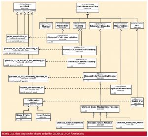
Due to its different layers of abstraction, prototyping of the GLONASS L1 C/A signal was done rapidly in the code base. Figure 2 shows the blocks of code added to the system and its object oriented properties relationship with the core blocks of the receiver. Note that the figure only displays the blocks created or modified for GLONASS L1 C/A, and is by no means a detailed Unified Modeling Language (UML) diagram of the objects present in the platform. It is worth mentioning that the GNSS-SDR platform uses some of the key concept ideas of GNU Radio in the sense that it has an abstract block upon which all other interfaces and implementations are based. The block GNSSBlockInterface defines a set of basic properties common to all objects that inherit its properties. Direct descendants of this GNSSBlockInterface are interfaces that describe the software receiver, which range from a Channel interface to a PVT interface that serves as the top layer of the software. Once the basic layers of the GNSS-SDR are defined, then the adapter blocks are used to implement the basic methods of these interfaces and define some others if required (C. Fernández-Prades et alia, 2012). This in particular allows for an extremely flexible design in which adapter blocks could be swapped depending on the algorithm or signal to be processed. At the same time, each adapter block’s dependencies connect GNSS-SDR with the GNU Radio API inheriting some functionality of the gr::block upon which the entire GNU Radio platform is defined.
GLONASS FDMA Signal Model
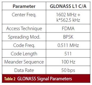
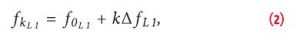
GLONASS satellites orbit Earth at a 64.8 degree inclination (GPS uses six planes at 55 degrees). This inclination is ideal to ensure good coverage of polar latitudes, where a significant portion of the Russian Federation territory is located. The satellites have an altitude of around 19,100 kilometers in a nearly circular orbit with eccentricity near 0 (again, see Additional Resources). The previous orbital parameters make the satellites have an orbital period of 11 hours, 15 minutes, and 28 seconds, with repeating ground tracks every 7 days, 23 hours, 27 minutes, and 28 seconds. As mentioned before, the GLONASS system uses FDMA for its C/A signal. The system now has allocated 14 frequency channels in the L1 band that are spaced from each other with a constant frequency offset. The received signal can be described as per Equation (1): where: PC is the power of signals with C/A code, C k is the C/A code sequence assigned to satellite number k, τ is the code phase received in ground, Dk is the navigation data sequence, f kL1 is the nominal value of the FDMA L1 carrier frequencies, f d is the Doppler frequency seen in the ground, and n is the received noise. The nominal values of the FDMA L1 carrier frequencies are defined by Equation (2): where: k = represents the frequency channel, f 0L1 = 1602 MHz for the GLONASS L1 band, and ∆f L1 = 562.5 kHz frequency separation between GLONASS carriers in the L1 band. Since a total of 24 satellites populate the constellation and only 14 frequency channels are available, GLONASS satellites will share some frequency channels but only when in antipodal positions, i.e., satellites in opposite position on Earth. General parameters of this signal are defined in Table 2.

Signal Source & Signal Conditioner
The Signal Source block hides the complexity of accessing each specific signal source, providing a single interface to a variety of different implementations. Each implementation will target the parsing of data from specific front ends or custom formats in a raw file. It will then transform it to the standard used by the receiver. Using the NT1065 front end (N. C. Shivaramaiah et alia) data was collected across the GLONASS L1 frequency band and minor modifications to the signal source blocks were added to parse the data previously stored in a file. The Signal Conditioner block oversees adapting the sample bit depth to a data type tractable at the host computer running the software receiver, and optionally intermediate frequency to baseband conversion, resampling, and filtering. Regardless of the selected signal source configuration, this interface delivers a sample data stream to the receiver processing channels, acting as a facade between the signal source and the synchronization channels.
Acquisition
The role of an Acquisition block is the detection of signals from a given GNSS satellite. As per Equation (1),
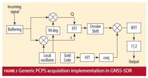
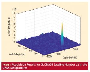
in the case of a positive detection, it should provide coarse estimations of the code phase (τ) and the Doppler shift (f d ) to initialize the delay and phase tracking loops. Since GLONASS FDMA uses a gold code to detect time delay, acquisition techniques developed for GPS L1 C/A were modified to accommodate GLONASS processing. GLONASS signal acquisition can be seen as that of GPS L1 C/A, but instead of looping over different Pseudo Random Noise (PRN) code values, the code will loop over a single code at different frequency channels k. After frequency channel removal, the typical Parallel Code Phase Search (PCPS) algorithm (D. Akopian) (Figure 3) can be used for acquisition. Most importantly, this approach reuses previously developed blocks in the platform, which allows for this flexible level of abstraction within the internal software architecture. Figure 4 shows the acquisition results for a GLONASS satellite in real data collection. The significant peak in the figure indicates a positive signal detection on a frequency channel.
Tracking
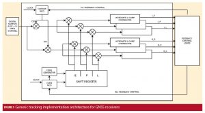
The Tracking block is also receiving the data stream xIN, but does nothing until it receives a “positive acquisition” message from the control pane, along with the coarse estimations τacq and f dacq. Then, its role is to refine such estimations and track their changes along time. Three parameters are relevant for signal tracking: the code phase (τ), Doppler frequency (f d ), and carrier phase (ψ). As with the signal acquisition, GLONASS L1 C/A signal tracking reuses blocks developed for the legacy GPS L1 C/A signal tracking. The main difference to consider is the removal of the frequency channel offsets from IF due to its FDMA properties. After carrier removal happens, tracking for GLONASS could be treated as a typical GPS L1 C/A tracking module (Figure 5). Re-usability of existing
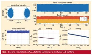
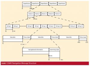
blocks reduces code complexity and highlights the benefits of flexibility within the platform. Tracking results are shown in Figure 6. The values for the C/ N0 , carrier frequency (relative to nominal frequency channel), and code frequency are shown in the bottom, while a discrete time scatter plot showing phase lock with bits of navigation is shown up top. Due to the effect of the meander sequence present in the GLONASS Navigation Message (GNAV) message (see Additional Resources), bits of navigation need further processing before decoding can be applied to the signal. WORKING PAPERS FIGURE 3 Generic PCPS acquisition implementation in GNSS-SDR Incoming signal Output Buffering Local oscillator Circular Shift Gold Code IFFT 1 | 2 FFT FFT 90 deg conj Q r FIGURE 4 Acquisition Results for GLONASS Satellite Number 22 in the GNSS-SDR platform Code Delay (chips) 0 –10000 –5000 0 5000 100 200 300 400 Dopler Shift (Hz) Acquisition metric (µ) ×1013 18 16
Telemetry Decoding
Telemetry Decoding block decodes the navigation message for the signal. Once the signal is properly tracked , the Tracking block will start to populate the required fields in the gnss_ syncro object, which ser ves as the pipeline between the implementation of the blocks in the channel. The symbols populated in gnss_syncro will be used to decode the GNAV message after the meander sequence has been removed, as shown in Figure 7. GNAV decoding is a very straightforward process that requires careful bookkeeping between the bit position for each of the fields in the string, which is carefully described in its Interface Control Document (ICD) (see Additional Resources). Following the design pattern of GNSS-SDR, the decoded data was divided into four objects, named Glonass_Gnav_Ephemeris, Glonass_Gnav_Navigation_Message, Glonass_Gnav_Utc_Model, and Glonass_Gnav_Almanac, holding the relationships described in Figure 2.
Observables
The Observables block generates by default three types of measurements for processing in the navigation solution computation. These measurements include pseudo-ranges, accumulated carrier phase, and Doppler frequencies. All of this is generated through a single object called Hybrid_Observables, which computes these measurements in a generic way across all channels. As such, work in this area was minimalistic and only consisted of managing the information flow between the Telemetry Decoder and Observables block. Nevertheless, a proper definition of the measurements as per the GNSS-SDR platform is offered for clarity. Pseudorange Measurements The basic observation equation for the pseudorange as given by K. Borre et alia, assuming that is geometric pseudorange from satellite k to the receiver i, c is speed of light, δti is receiver clock offset, δtk is satellite clock offset, is tropospheric delay, and is ionospheric delay, is Accumulated Carrier Phase Measurements Following the same definition of pseudorange, the carrier phase can be defined as a measurement of ranges as defined in Equation (4) The last term of the equation represents the initial unknown ambiguity in the cycle number relating to the distance between receiver and satellite. However, when applying a differentiation of continuous carrier phase measurements, ambiguities in the number of cycles are eliminated due to the fact that for continuous carrier phase measurements, the ambiguity will be the same in both cases. The result is a measurement of the range rate defined as:
Doppler Shift Measurement
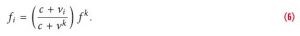
The Doppler effect is the change in frequency for an observer (in this case, the GNSS receiver i) moving relative to its source (in this case, a given GNSS satellite k). Equation (6) gives the relationship between observed frequency f i and emitted frequency f k : Since the speeds of the receiver vi(t) and the satellite v k are small compared to the speed of light c, the difference between the observed frequency f i and emitted frequency f k can be approximated by Then, the Doppler Effect measurement can be written as where r r (t) and vr (t) are the position and velocity of the receiver at the instant t. The term v (s)(t(s)) − vr (t r ) T is the radial velocity from the receiver relative to the satellite, and and are the receiver and satellite clock drift, respectively. The Doppler Effect measurement is given in Hz.
PVT
The PVT solution in GNSS-SDR currently uses a module created based on the RTKLib library. As such, the GLONASS integration to this module was only in charge of providing the necessary conversion tools to translate from
the GNSS
-SDR modules to the RTKLib input. All conversion parameters were developed following the description of the RTKLib API library (T. Takasu and A. Yasuda). To test the code developed and presented in this work, a GNSS data logger using the NT1065 front end was used. The data logger of this device allowed for mult
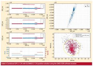
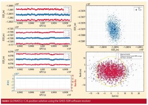
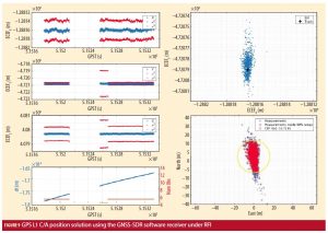
i-frequency, multiband collection at the same time. For this study, the specific configuration loaded in the device’s firmware targeted a data collection for GPS L1 C/A, GLONASS L1 C/A, GLONASS L2 C/A, and GPS L2C, simultaneously. Figure 8 shows the first position solution for GLONASS L1 CA signals ever achieved by GNSSSDR. The figure shows the position of the receiver in the Earth Centered Earth Fixed (ECEF) coordinate frame with the position covariance for each of the components. The figure also plots the clock variation error, the number of observations used during the position computation, and the estimated position across the X and Y components relative to the true antenna position. Finally, the 90% Circular Error Probable (CEP) statistic, as per the description by G. M. Siouris, is shown. Case Study: Performance under RFI A Radio Frequency Interference (RFI) tone was introduced in the data set collected for the GPS L1 C/A signal, simulating a scenario where a common Continuous Wave (CW) PPD device will null the operating band of the signal. Typical RFI devices, such as those described in Table 1, were studied and a pulse mimicking their behavior was generated to null the band. The simulated interference in the band was inserted 60 seconds into the collected data (allowing initial position solution computation) and lasted for about 20 seconds. Figure 9 shows the position solution generated by GNSSSDR under the presence of a nulling RFI tone. After 60 seconds of data processing, the position solution stops, resuming around 50 seconds later. This indicates the inability of the receiver to compute its position. Also of interest is the fact that after the RFI resumes, the receiver will need to spend time to decode the ephemeris data before being able to compute a position solution unless some intelligent signal processing technique is applied to reuse the previous decoded ephemeris. If under the assumption of this experiment, a PPD device as in Table 1 is used, then the GLONASS FDMA signals could be used to keep the position solution active, even during the jamming period. Results of this scenario are shown in Figure 10. The receiver, when using a combined solution of GPS L1 C/A and GLONASS L1 C/A, is able to provide position estimates even though the RFI tone is nulling the GPS L1 band. Due to the reduction in the number of observations when the GPS L1 band is nulled, a small performance hit is seen but no loss of the position solution happens, which is the cumbersome mission of the proposal.
Conclusion
This article presents the first-ever position solution of GLONASS L1 C/A in the GNSS-SDR platform. This addition will allow the receiver to take advantage of the FDMA signals available in the radio navigation spectrum and will open a new set of tools for the scientific community to use in the diverse field of GNSS processing. Addition of the GLONASS L1 C/A in a combined position solution is a simple but effective technique to aid the overall position solution of a receiver when in the presence of RFI or spoofing attacks. We also present a detailed description of the process of signal addition to the GNSS-SDR platform and serves as a template for developers with the intention of contributing to the platform.
Acknowledgments
This material is based upon work partially supported by the National Science Foundation Graduate Research Fellowship under Grant No. DGE 1144083 and the Google Summer of Code (GSoC) 2017 program. Special thanks to the GNSS-SDR team mentors during the GSoC 2017 program including Luis Esteve, Carles Fernandez–Prades and Jordi Vilà Valls. In addition, special thanks to Professor Dennis M. Akos for providing some of the data sets used during the testing stage and to the editors of this manuscript Dr. Nagaraj Channarayapatna Shivaramaiah, Sara Hrbek, and members of the University of Colorado at Boulder Wri
ting Center. Manufacturers The first software receiver described in the GNSS Software Receivers section of the article and in Additional Resources (Pany et alia, 2012) is the SX3 software receiver developed by IFEN GmbH from Poing, Germany. Another commercial receiver discussed in the section was the ARAMIS from iP-Solutions with offices in Japan, UK and the U.S. Additional Resources 1. Akopian, D., “Fast FFT based GPS Satellite
Acquisition Methods,” IEE Proceedings – Radar, Sonar and Navigation, Volume: 152, Issue: 4, 2005 2. Borre, K., D. Akos, N. Bertelsen, P. Rinder, and S. Jensen, A Software-Defined GPS and Galileo Receiver: A Single-Frequency Approach, Applied and Numerical Harmonic Analysis, Birkhäuser, 2007 3. Fernández–Prades, C., J. Arribas, P. Closas, C. Avilés, and L. Esteve, “GNSS-SDR: An Open Source Tool For Researchers and Developers,” Proceedings of the ION GNSS 2011 Conference, Portland, OR, 2011 4. Fernández–Prades, C., J. Arribas, L. Esteve, D. Pubill, and P. Closas, “An Open Source Galileo E1 Software Receiver,” Proceedings of the 6th ESA Workshop on Satellite Navigation Technologies (NAVITEC ’12), ESTEC, Noordwijk, The Netherlands, 2012 5. Fonzo, A. D., M. Leonardi, G. Galati, P. Madonna, and L. Sfarzo, “Software-Defined-Radio Techniques Against Jammers for In-Car GNSS Navigation,” 2014 IEEE Metrology for Aerospace (MetroAeroSpace), 2014 6. Goff, S., “Reports of Mass GPS Spoofing Attack in the Black Sea Strengthen Calls for PNT Backup,” Inside GNSS, 2017 7. Kraus, T., R. Bauernfeind, and B. Eissfeller, “Survey of In-Car Jammers – Analysis and Modeling of the RF Signals and IF Samples (Suitable for Active Signal Cancelation),” Proceedings of the 24th International Technical Meeting of the Satellite Division of The Institute of Navigation (ION GNSS 2011), Portland, OR, 2011 8. Pany, T., Navigation Signal Processing for GNSS Software Receivers, GNSS Technology and Applications Series, Artech House, 2010 9. Pany, T., N. Falk, B. Riedl, T. Hartmann, G. Stangl, and C. Stöber, “An Answer for Precise Positioning Research,” Innovation: Software GNSS Receiver, 2012 10. Petrovski, I., and T. Tsujii, Digital Satellite Navigation and Geophysics: A Practical Guide with GNSS Signal Simulator and Receiver Laboratory, Digital Satellite Navigation and Geophysics, Cambridge University Press, 2012 11. Revnivykh, I., “Glonass Programme Update,” 11th Meeting of the International Committee on Global Navigation Satellite Systems, Sochi, Russian Federation, 2016 12. Russian Institute of Space Device Engineering, “Global Navigation Satellite System (GLONASS) Interface Control Document, Navigational Radio Signal in Bands L1, L2,” Technical Report, Moscow, 2008 13. Shivaramaiah, N. C., D. M. Akos, and K. Yan, “A Multi-band GNSS Signal Sampler Module with Open-Source Software Receiver,” Proceedings of the 29th International Technical Meeting of the Satellite Division of The Institute of Navigation (ION GNSS+ 2016), Portland,
OR, 2016 14. Siouris, G. M., Aerospace Avionics Systems : A Modern Synthesis, Academic Press, 1993 15. Suzuki, T. and N. Kubo, “GNSS-SDRLIB: An OpenSource and Real-Time GNSS Software Defined Radio Library,” Proceedings of the 27th International Technical Meeting of the Satellite Division of The Institute of Navigation (ION GNSS 2014), Tampa, FL, 2014 16. Takasu, T. and A. Yasuda, “RTKLIB ver. 2.4.2 Manual,” No. C, 2013
Authors
Damian Miralles is a graduate student in the Department of Aerospace Engineering Sciences at the University of Colorado Boulder. He received a B.S. in Electrical and Computer Engineering from the Polytechnic University of Puerto Rico. His research interests are in GNSS receiver technologies, software defined radio and digital signal processing.
Gabriel F. P. Araujo is an undergraduate student in the Faculty of Technology at the University of Brasilia, Brazil, and scholarship researcher at LARA (Automation and Robotics Laboratory). He works with robotics estimation and navigation. He is currently working with SDR development, a software-defined radio for mobile robot localization using multi-constellation GNSS systems.
Em. Univ.-Prof. Dr.-Ing. habil. Dr. h.c. Guenter W. Hein is Professor Emeritus of Excellence at the University FAF Munich. He was ESA Head of EGNOS & GNSS Evolution Programme Dept. between 2008 and 2014, in charge of development of the 2nd generation of EGNOS and Galileo. Prof. Hein is still organizing the ESA/JRC International Summerschool on GNSS. He is the founder of the annual Munich Satellite Navigation Summit. Prof. Hein has more than 300 scientific and technical papers published, carried out more than 200 research projects and educated more than 70 Ph. D.´s. He received in 2002 the prestigious Johannes Kepler Award for “sustained and significant contributions to satellite navigation” of the US Institute of Navigation, the highest worldwide award in navigation given only to one individual each year. G. Hein became a Fellow of ION in 2011. The Technical University of Prague honored his achievements in satellite navigation with a Doctor honoris causa in Jan. 2013. He is a member of the Executive Board of Munich Aerospace since 2016.