
In this column, guest contributor Mike Horton from ANELLO Photonics introduces a new gyro technology that bridges the market gap between high-performance (but expensive) sensors (fiber-optic and ring laser gyros) and low-cost (but imprecise) MEMS gyros. Benefits of improved gyro quality enabled by SIPHOG are illustrated, including GNSS-denied navigation scenarios.
Inertial navigation is an extremely well understood and widely used approach to standalone Position, Navigation and Timing (PNT). The challenge with inertial navigation is that small inertial sensor errors expand quickly into large positional errors. Therefore, the required performance level and sensor bias of the component gyroscope and accelerometers is extremely difficult to achieve in practice in a small affordable form factor.
Today’s small and low-cost MEMS-based inertial measurement units (IMUs) typically can only navigate standalone for tens of seconds before accumulated errors exceed acceptable margins of error. As a result, the majority of precision navigation applications found in industrial, aerospace and military applications require the use of a fiber-optic gyro (FOG) or a ring laser gyro (RLG). A typical FOG-based IMU consumes 8 watts of power, requires 28 cubic inches of volume and costs more than $15,000. RLG-based devices are equally power hungry, large and expensive. In addition, RLG-based solutions are heavy because of the large volume of solid glass used in their construction.
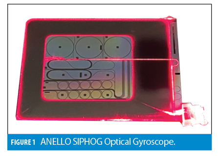
This large market gap between high-performance optical gyros and low-cost MEMS gyros was the impetus for ANELLO Photonics to integrate the proven performance of a fiber-optic gyro into a chip-scale silicon photonic platform. ANELLO has named this device the SIPHOG, which stands for silicon photonic optical gyro. The first generation SIPHOG has less than 0.5°/hr drift. The benefits of low gyroscope drift for GPS-denied land navigation are presented in this article.
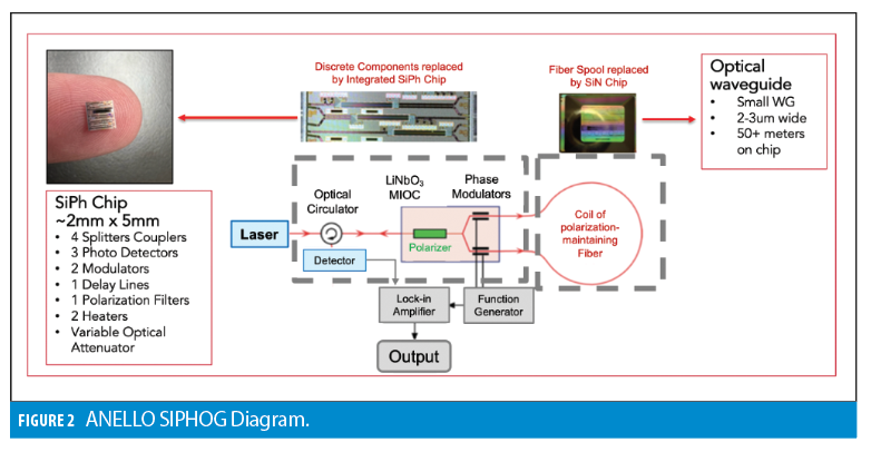
The SIPHOG block diagram is shown in Figure 2. On the right, an ANELLO-developed silicon nitride waveguide replaces the traditional fiber coil. On the left, the ANELLO-developed photonic integrated circuit (PIC) replaces the splitters, couplers, polarizers, modulators and photo detectors.
The device operation follows the principle of a classic interferometric Sagnac-effect based angular rate measurement. There are numerous technical challenges to developing integrated silicon optical gyros. It requires the development and fabrication of fundamental processing technology, planar waveguide design, silicon photonics integrated circuits and IMU electronics. ANELLO has been issued 16 patents to date.
Application to Land Vehicle Navigation
Land vehicles operate in areas where multipath, signal interference and full-signal loss all present frequently occurring challenges to standalone GNSS navigation, particularly in urban environments. Active spoofing and jamming threats are now commonplace in geo-politically contested regions such as Ukraine, and reports of these dangerous GNSS signal disturbances in non-contested regions are on the rise. Inertial navigation approaches can mitigate these GPS errors; however, mitigation requires extended long-term dead reckoning of many minutes. The combination of the SIPHOG optical gyroscope with a vehicle odometer is demonstrated as a practical solution to long-term dead reckoning.
In an inertial navigation system for a wheeled land vehicle, heading is determined by the fusion of GPS heading and IMU heading. IMU heading drift is principally impacted by the z-axis or “heading gyroscope.” Magnetic compass heading generally performs poorly on land vehicles because of the large hard-iron and soft-irons of the vehicle itself as well as neighboring vehicles. GPS heading is the best source of heading in a wheeled vehicle. Distance travelled is measured by a combination of linear accelerometers and an external vehicle odometer. A Kalman filter is used to fuse these measurements and actively calibrate sensor errors.
To gain an intuition for the magnitude and relative contribution of error sources in land vehicle dead reckoning, a simplified error model consisting of three basic error sources is presented:
• θe Initial Heading Error, deg
• Ωb Gyro Bias Drift, deg/hr
• Le Odometer Scale Factor Error, %
Additional formula terms are v for average vehicle velocity in meters per second, and t for the length of time in seconds for unaided GPS-denied dead reckoning. These errors contribute to 2D horizontal position drift as follows:
• Odometer Error v Le t
• Initial Heading v θe t
• Z-Axis Gyro Drift v Ωb t2
How these errors work and contribute to drift is easy to understand without sophisticated math or computer simulation.
Without any directional error, position error will still grow as distance is travelled due to errors in the odometer. When the GNSS signal is lost, assuming the vehicle’s wheels are not slipping, an odometer accumulates error linearly with velocity and time. The proportionality constant Le represents the error in odometer scale factor calibration at the time of GNSS signal loss. This simplified odometer error formula also assumes the odometer lever arm is compensated, for example, to correct the odometer signal in turns where the inner rear-wheel travels less distance than the outer rear-wheel. A typical Le value for a well calibrated odometer is 0.1%.
For directional errors, an initial heading error points the solution in the wrong direction at the moment GPS is lost. The dead-reckoning solution follows this incorrect initial direction, accumulating error linearly with time and velocity. If the INS has been running smoothly and the vehicle is first driven at normal road speeds, this initial heading error can be as small as 0.05 degrees.
The z-axis (heading) gyro drift causes the solution to drift over time, increasing the heading error beyond the initial heading error. Assuming the gyro bias error Ωb is the dominant gyro error in time t, the relative contribution is v Ωb t2. The time squared error dependence is very significant; this gyroscope-induced drift error will grow quadratically instead of linearly as compared to the first two error mechanisms described.
To manage the quadratic error growth, the use of a low-drift optical gyro such as the SIPHOG provides a large benefit. MEMS gyros have large thermal drifts that are difficult to fully calibrate. In addition, a typical MEMS gyro sensor has a measurable linear acceleration sensitivity (g-sensitive bias) and vibration sensitivity (g2 bias error) that changes the gyro bias error Ωb when the road surface, vehicle speed and inclination varies. As a result, a Kalman filter may estimate the gyro bias error to a more limited degree.
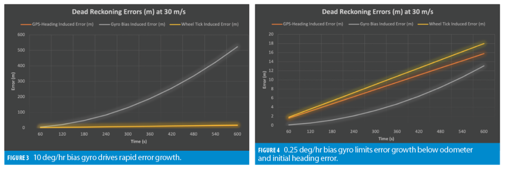
A typical bias error of 10 deg/hr is common even for MEMS-gyros that have a far better Allan deviation bias instability value. An optical gyro, on the other hand, has stable performance over temperature, linear acceleration and vibration. For a tactical grade optical gyroscope, Ωb can be reduced to values in the 0.1–0.5 deg/hr range and a Kalman filter can reasonably achieve the Allan deviation bias instability value in practice.
Applying these values and using a speed of 30 m/s, some representative dead-reckoning errors are shown in Figures 3 and 4. Figure 3 shows that the gyro bias-induced error is the dominant error when the z-axis gyro drift is 10 deg/hr. Figure 4 shows this error is well contained over a 10-minute signal loss, and it reflects the importance of a low-drift gyro to the solution.
Test Results
In a typical inertial navigation system on-road test, the GNSS signal is either physically removed or the vehicle is driven into a tunnel to block the signal. However, these tests may not capture misleading or partially incorrect GNSS data that occurs in a GNSS challenged environment.
To conduct real-world testing, ANELLO participated in the USAF 746th Squadron NAVFEST 2022 to better understand long-term dead-reckoning during GNSS jamming and spoofing. An ANELLO Evaluation Kit (EVK) was tested alongside a high-end MEMS reference system during NAVFEST at White Sands Missile Range. The 746th Squadron gave ANELLO permission to share certain results.
During NAVFEST, the ANELLO EVK was tested with three popular automotive and industrial GNSS engines. The ANELLO EVK and inertial reference system were configured to accept wheel speed aiding. Two Pegasem WSS4 wheel speed sensors on the left and right rear wheels were installed. The average wheel speed was computed and transmitted.
Data was collected across three nights of testing and compiled into one master data set for analysis. The intervals of spoofing and jamming ran from 15 minutes to 1 hour, and the impact to the GNSS solution resulted in frequent full signal loss or grossly misleading data. To illustrate, Figure 5 shows the dramatic extent to which the GNSS signal was impacted by spoofing.
Sensor fusion algorithms generally use GNSS solution figures of merit such as HDOP to determine when to trust the GNSS versus when to trust the IMU. The NAVFEST testing shows this strategy may not work with all receivers because they may not be aware that their internal position solution is degraded in a spoofing environment.
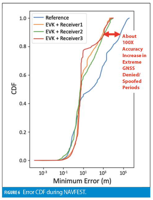
During NAVFEST, the reference solution exhibited large errors that, in some cases, significantly exceed 10 km from the road. Therefore, for error analysis, the 2D error is computed for both the ANELLO EVK and the reference using the minimum distance from the solution to a point on the center line of the road. In other words, the road was used as the reference.
A cumulative distribution function (CDF) of all data collected at NAVFEST is plotted in Figure 6. The ANELLO EVK with odometer significantly outperformed the MEMS-based reference with odometer and reflects how critical good IMU performance is for dead reckoning. Even with wheel speed aiding, navigation performance drift due to the IMU grows (at least) quadratically with time. In reality, once the error grows large enough (beyond the linearization region), the INS solution performance collapses with additional unbounded rapid error growth. This issue can be observed in the long tail of the CDF of the MEMS reference solution.
Benefits of the Visual Odometer
Visual sensors such as LiDAR and cameras create more advanced methods of vehicle speed measurement than that of a simple wheel speed sensor. These sensors will not experience errors due to vehicle slip and also can provide a 3D velocity measurement as opposed to the 1D odometer measurement. Notwithstanding the challenges of additional cost and complexity as well as weather and environment sensitivity, a vision-based odometer can further enhance long-term dead reckoning performance.
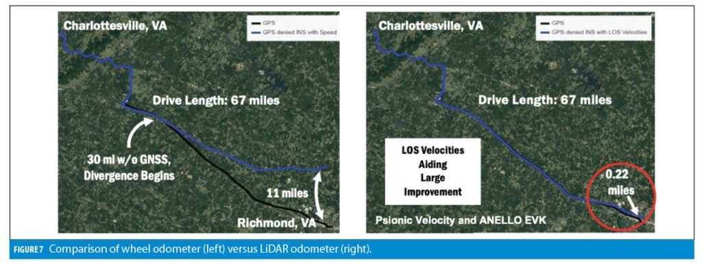
Psionic used FMCW LiDAR in combination with the ANELLO EVK to demonstrate the performance benefits of a LiDAR plus optical gyroscope integration. During Psionic’s testing, a 67-mile, 90-minute route was driven without GNSS. A comparison between an ANELLO EVK with wheel odometer was made to a
solution fusing the ANELLO EVK with FMCW LIDAR.
As shown in Figure 7, the wheel odometer solution works well for the first 30 minutes of the GNSS denied test and then begins to drift significantly. The ANELLO EVK with LiDAR-based odometer solution traversed the full 67-mile, 90-minute course with only 0.22 miles (0.35 km) of error. This high-performance long-term dead reckoning has previously only been possible using extremely high-end inertial equipment.
Conclusion
Long-term GNSS-denied dead reckoning is critically dependent on inertial sensor performance. The use of integrated silicon photonics is a new direction for high-accuracy inertial sensors that can meet the challenge of long-term dead reckoning. A combination of wheel speed sensors and an optical gyro-based IMU shows good performance for GNSS outages of more than 10 minutes, and the use of vision sensors with an optical gyroscope shows such performance can be extended to more than an hour.
Author
Mike Horton is the CTO of ANELLO Photonics. Mike is an experienced executive with over 20 years in the gyro, sensor and navigation industry. He was CEO and co-founder of Crossbow Technology, a leader in developing MEMS sensor systems for aircraft, military, defense and commercial applications. Mike is considered a world recognized expert in sensor technology.


