
Combining multipath assisted positioning and fingerprinting using deep learning brings the best of two worlds together: low complexity and good performance.
MARKUS ULMSCHNEIDER, CHRISTIAN GENTNER AND ARMIN DAMMANN, GERMAN AEROSPACE CENTER (DLR), INSTITUTE OF COMMUNICATIONS AND NAVIGATION
In scenarios with good view-to-sky conditions, global navigation satellite systems (GNSSs) can provide positioning with performances that meet the requirements for a multitude of services and applications. However, in urban canyons and particularly indoors, their performance may be degraded drastically due to a low received signal power, multipath and non-line-of-sight (NLoS) propagation, or obstruction by walls and buildings, for example. While there are plenty of approaches for indoor positioning in the literature, there is still no single approach or technology that has emerged as the future indoor positioning method.
In this article, we focus on radio-based positioning systems. A big advantage of these systems is that radio signals tend to be available in abundance in populated areas. For example, fifth generation (5G) or wireless local area network (WLAN) signals may be exploited for positioning in indoor scenarios. Compared to GNSS signals, their power at a receiver is typically significantly higher. However, multipath and NLoS propagation also degrade the positioning performances when using such signals—if standard positioning methods are used.
In multipath assisted positioning schemes, multipath propagation is exploited for localizing a user. Scattered and reflected signal components are regarded as line-of-sight (LoS) signals from so called virtual transmitters. While the locations of these virtual transmitters depend on the scenario and are typically unknown, they can be estimated jointly with the receiver location with simultaneous localization and mapping (SLAM) [1-3].
We recently introduced a multipath assisted positioning approach called cooperative Channel-SLAM in [4], where users cooperate by exchanging maps of estimated transmitter positions. The transmitter is used as a general term that refers to both physical and virtual transmitters.
Single user Channel-SLAM works in two steps. In the first step, a channel estimator estimates and tracks the parameters of signal components of the received signal over time. In the second step, these channel parameters are used in a Rao-Blackwellized particle filter to jointly track the receiver location and estimate the positions of the transmitters. In cooperative Channel-SLAM, multiple users going through the same scenario cooperate by exchanging maps of estimated transmitter positions. Each user is in a local coordinate system, though, which has an unknown relative rotation and translation to the coordinate systems of other users. Estimating these transformation parameters and the transmitter correspondences is a crucial element of cooperative Channel-SLAM and denoted by the term map matching. The term user may refer to a user or the radio receiver the user is equipped with, depending on the context.
We have shown before that the positioning error [4] and the entropy of the maps [5] converge in cooperative Channel-SLAM. Nevertheless, the scheme suffers from a high complexity both in the channel estimation, the particle filter and map matching.
Fingerprinting schemes represent a different approach to indoor localization [6], [7] and work in two stages. In the offline stage, features at known locations are collected and stored in a database. Such features could be information on the wireless channel or magnetic signatures, for example, and they are called fingerprints.
When using wireless radio signals such as WLAN or Bluetooth, received signal strength indicator (RSSI) values or channel state information (CSI) are often used as fingerprints. In the online stage, users can be localized by matching fingerprints taken at their location against the database.
Fingerprinting methods with wireless radio signals can be easily built on top of existing infrastructure, such as WLAN systems. The key assumption is certain features of radio signals correlate with certain locations. On the one hand, it is assumed that fingerprints taken at nearby locations are close to each other in some metric. On the other hand, fingerprints taken at locations far away from each other are assumed to be far away in that metric. Fingerprinting is hence a data-driven approach and does not require complex models. In particular, no synchronization between transmitter and receiver is necessary as for time of arrival (ToA) based positioning methods, for example.
A major drawback of fingerprinting schemes is the tedious collection of features in the offline stage. For good localization performance, fingerprints need to be collected at many positions. A precise location needs to be stored for every fingerprint, requiring a precise localization ability in the offline stage. In addition, changes in the environment can decrease the positioning performance significantly. Updating the fingerprint database to adapt to such changes may take a lot of effort. Some research, therefore, aims to update fingerprints in the online stage [8].
Recently, techniques from machine learning have been used to improve performance and compensate for the disadvantages of fingerprinting, including k-nearest neighbors (kNN) [9], support vector machine (SVM) and deep neural networks (DNNs) [7]. In the offline stage of the latter example, fingerprints and the user location are in principle used to train a DNN. In the online stage of fingerprinting, evaluation of the neural network yields the user location. Compared to competing approaches, DNNs tend to have better generalization abilities [10].
We propose a novel hybrid scheme combining cooperative Channel-SLAM with fingerprinting methods using a DNN. The scheme works in two stages and will be donated by the term DNN-CC-SLAM. In the offline stage, users navigate through a scenario with cooperative Channel-SLAM. The ToA estimates from the channel estimators together with the respective estimated positions are stored in a fingerprint database.
After a sufficient number of ToA fingerprints are available, a DNN is trained to predict the user location from these estimated ToAs. Hence, the fingerprints are not collected in a classical way with a ground truth positioning system, but are nuisance parameters from cooperative Channel-SLAM. In particular, no external hardware or equipment needs to be installed for collecting or updating the fingerprints. The fingerprint collection can be regarded as a crowd-sourcing scheme.
In the online stage, further users can exploit the trained DNN for positioning. For estimating the ToAs of signal components in the online stage, estimators with low complexity exist. Hence, the online stage of DNN-CC-SLAM is crucially less complex than cooperative Channel-SLAM.
Compared to standard fingerprinting approaches, we facilitate the tedious collection of features in the fingerprinting scheme with external infrastructure for a precise localization reference. The fingerprint database can be updated with cooperative Channel-SLAM from time to time or when needed, for example, by one or more dedicated users or by a certain percentage of users navigating in the scenario.
Cooperative Channel-SLAM
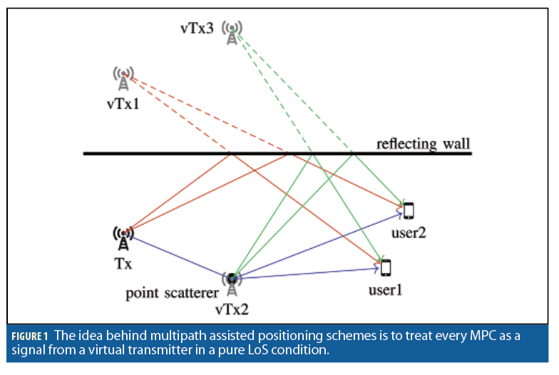
Figure 1 illustrates the idea behind multipath assisted positioning with one physical transmitter labeled Tx and two users. For clarity, possible LoS propagation paths are omitted. The multipath components (MPCs) reflected at the wall before arriving at the users are regarded as LoS components from the virtual transmitter vTx1, whose location is at the physical transmitter mirrored at the wall. This case can be generalized to reflections at straight surfaces. Likewise, the MPCs scattered at the point scatterer before arriving at the users are regarded as LoS signals from the virtual transmitter vTx2. In the case of scattering at a point scatterer, the respective virtual transmitter is located at the scatterer. While our model of a point scatterer is such that the impinging signal energy is distributed uniformly to all directions, structures such as pillars may be well approximated as point scatterers in practice.
Geometrical considerations reveal three important properties of virtual transmitters. First, in the case of reflections of the signal at straight surfaces and scattering at point scatterers, the location of the corresponding virtual transmitters is independent from the user position. While in the case of reflections the reflection point may be different for different user positions, the virtual transmitter location stays the same. Second, in the case of reflection at straight walls, the respective virtual transmitter is perfectly time synchronized to the physical transmitter. In the case of scattering, there is a delay offset between the physical and the virtual transmitter corresponding to the actual propagation time of the signal from the physical to the virtual transmitter. This delay offset can be interpreted as a clock offset. Third, the concept of single interactions of the signals with straight surfaces and point scatterers can be extended to multiple interactions in a straightforward manner.
In Figure 1, an example of such a case is illustrated by the green lines, where the transmit signal is first scattered at the point scatterer and then reflected by the wall before arriving at the users. Accordingly, the resulting virtual transmitter, vTx3, is at the location of the point scatterer mirrored at the wall. This virtual transmitter again has a delay offset corresponding to the propagation time of the signal from the physical transmitter to the point scatterer.
Channel-SLAM assumes a linear multipath channel with static physical transmitters and a mobile user. We will assume only one physical transmitter for clarity, while the generalization to multiple physical transmitters is straightforward if the signals of the physical transmitters can be separated in at least one domain such as time or frequency. The movement of the user equipped with the receiver makes the channel time variant.
The transmit signal s(t) from the physical transmitter arrives at the user via different propagation paths as in Figure 1. Each signal component arriving at the user corresponds to one propagation path. The jth signal component is characterized by the complex amplitude aj(t) and the ToA τj(t). The received signal as the user is then modeled as
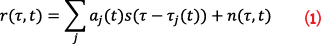
at one antenna element, where n(τ,t) is a random process incorporating additive white Gaussian noise (AWGN) and dense multipath components. While the number of signal components in Equation 1 may be infinite in theory, it is limited by the receiver hardware in practice.
For channel estimation, we use the Kalman Enhanced Super Resolution Tracking (KEST) estimator [11], which works in two stages. In the inner stage, a maximum likelihood (ML) parameter estimator such as Space-Alternating Generalized Expectation-Maximization (SAGE) estimates the parameters of signal components on a snapshot basis. These parameters could be ToA, phase, amplitude, and angle of arrival (AoA), for example.
In the outer stage, KEST uses parallel Kalman filters to track these parameters over time. Each Kalman filter corresponds to one hypothesis on the model order, i.e., the number of signal components. At each time instant, a hard decision on the final model order is made. Thus, KEST tracks both the number and the parameters of signal components over time. Furthermore, due to the tracking with the Kalman filters, KEST establishes correspondences among signal components for neighboring time instants.
We assume the channel is constant for the length of one snapshot. A snapshot of the received signal is sampled at time instants k at the receiver and fed into KEST. The resulting parameter estimates relevant for Channel-SLAM, typically ToA and AoA, are stored in the vector zk. Because each signal component corresponds to one transmitter in Channel-SLAM, we denote both the number of signal components detected by KEST and also the number of transmitters at time instant k by NTX,k.
The state xu,k of the user at time instant k consists of their two-dimensional position pu,k and velocity vu,k. Because the transmitters are assumed static, the state xTX <j> k of the jth transmitter at time instant k consists of its location pTX <j>k and its clock offset τ0,k. The joint state of all NTX,k transmitters at time instant k is denoted by xTX,k.Note Channel-SLAM does not differentiate between physical and virtual transmitters. While the physical transmitter corresponds to the LoS signal and virtual transmitters correspond to MPCs, all transmitters are covered by the same model.
Channel-SLAM jointly estimates the history of the state of the user and of the states of the transmitters based on the estimates from the channel estimator and possibly control input, which may integrate additional sensors such as a gyroscope or an inertial measurement unit (IMU). The joint user and transmitter state at time instant k is denoted by xk. The respective state probability density function (PDF) for the history of this joint state can be expressed as
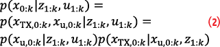
where x0:k describes the history of the variable x from time instants zero to k, and u1:k is the history of the control input from time instants zero to k .
The last factor in the last line of Equation 2 is the PDF regarding the transmitter states. We assume the estimates from the channel estimator for one signal component is uncorrelated with the estimates for other signal components, or that such a correlation is present for only a very short time. Hence, the transmitters are assumed independent from each other and the transmitter state PDF can be factorized as
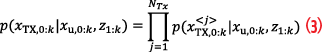
The minimum mean square error (MMSE) estimator x0:k,MMSE for x0:k can be calculated in principle as

exploiting Equations 2 and 3. Due to the highly non-linear measurement model and the high-dimensional state space, the joint user and transmitter state is estimated in Channel-SLAM with a Rao-Blackwellized particle filter, where Equation 2 yields the structure of the filter.
A particle filter is a Monte Carlo (MC) based method to solve recursive Bayesian estimation. The core idea is to represent the involved PDFs by a set of random, weighted samples in the state space. These samples are called particles, and each particle can intuitively be interpreted as a hypothesis for the true state.
In the Rao-Blackwellized particle filter in Channel-SLAM, the user state is approximated by a number of particles in the user state space. For each user particle in the user particle filter, the state of each transmitter is estimated with a transmitter particle filter independently from the other transmitters following the factorization in Equation 3. Separating the user state from the transmitters’ state decreases the computational complexity considerably. Estimating the states of each transmitter independently from the other transmitters’ states decreases the complexity even more.
The set of transmitter states estimated by a user is denoted by the term map. When multiple users navigate in the same area with Channel-SLAM, they can share such maps to obtain prior knowledge on the transmitters’ states. A map can be exploited by each user, and also improved by adding new transmitters to the map and improved transmitter state estimates with own measurements. In this cooperative Channel-SLAM scheme, the relative rotations and translations among the coordinate systems of the users need to be estimated, and correspondences among transmitters in different user maps need to be established. Estimating these transformation parameters and correspondences is denoted by the term map matching [12], and is an essential element of cooperative Channel-SLAM.
An important aspect in any SLAM scheme is data association, referring to associating measurements with landmarks. In radio-based SLAM, the problem at hand is to associate received signals with transmitters.
In Channel-SLAM, virtual transmitters correspond to reflections and scattering in the environment, and thus all transmitters send the same signal.
Following Equation 1, the signals differ only in parameters such as ToA, AoA, phase or amplitude, depending on the physical propagation channel. The tracking nature of the Kalman filters in KEST yields a data association for neighboring time instants. However, once track of a signal component corresponding to one propagation path is lost, for example due to blocking or the geometry of the scenario, KEST is not able to associate the same signal component once it is detected again. Associating signal components corresponds to associating transmitters. We use a robust multi-hypothesis data association scheme for Channel-SLAM [13], where the state space is expanded by data association decisions. Intuitively, each particle takes a hard decision on data association. Regarding the ensemble of particles with their respective decisions is a soft-decision method.
Fusion of Cooperative Channel-SLAM and Fingerprinting
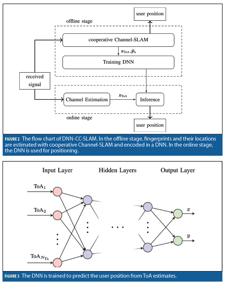
While cooperative Channel-SLAM shows a good positioning performance, the channel estimation, the particle filter and map matching cause a high computational complexity. Hence, we propose fusing the cooperative Channel-SLAM with fingerprinting to cushion the disadvantages of both schemes. A flowchart of our new scheme named DNN-CC-SLAM is depicted in Figure 2. In the offline stage, users navigate through the scenario with cooperative Channel-SLAM. From the channel estimators, the ToA estimates zToA are obtained from each user. Likewise, from the particle filter, we obtain the corresponding position estimates of each user, namely pˆu. While the AoAs and further channel parameters may be used as well as fingerprints in principle, we do not use them as they would lead to a much more complex channel estimation in the online stage. In addition, using AoA for fingerprinting would result in complex orientation estimation issues in the online stage.
The DNN is trained with the ToA and position estimates from the users. The DNN architecture is illustrated in Figure 3. It consists of an input layer, six hidden layers, and an output layer. All neighboring layers are fully connected. The number of neurons in the hidden layers are 1,000, 300, 200, 100, 50 and 20. The input to the DNN are the ToA estimates obtained from a channel estimator, leading to 32 input nodes. Because the number of detected signal components NTX may differ for different time instants, zero padding is applied if needed. The output is a two-dimensional position. The activation function of all nodes in the DNN is the rectified linear unit (ReLU) function. The DNN is trained with the Adam optimizer and the mean square error (MSE) as loss function.
The reason to take only estimated ToAs into account instead of the entire received signal is the complexity in training the DNN. The idea is to extract relevant features of the received signal to keep the dimension of the DNN rather small.
A very large input to the DNN would imply a more complex DNN and therefore an increased computational complexity in particular for training. Because a multipath channel typically is of sparse nature, we chose the ToAs of MPCs as relevant features. In particular, the ToAs are a nuisance parameter in cooperative Channel-SLAM and are available for training the DNN, keeping the additional complexity for the users low.
Once the DNN has been trained, more users in the scenario can use it for positioning in the online stage. While KEST is used as a channel estimator in cooperative Channel-SLAM, i.e., during the offline stage of the fingerprinting scheme, we have found superfast line spectral estimation (SFLSE) [14] to be very useful for channel estimation in the online stage. SFLSE is a Bayesian method for line spectral estimation using sparse estimation techniques. It inherently estimates relevant model parameters such as the noise variances and the model order. A big advantage of SFLSE is its very low complexity compared to other channel estimators, while keeping a comparable estimation accuracy [14]. The short-term data association provided by KEST is an important element for Channel-SLAM, but not necessary for fingerprinting. On our simulation machines, the SFLSE is on average about 75 times faster than KEST.
Simulations
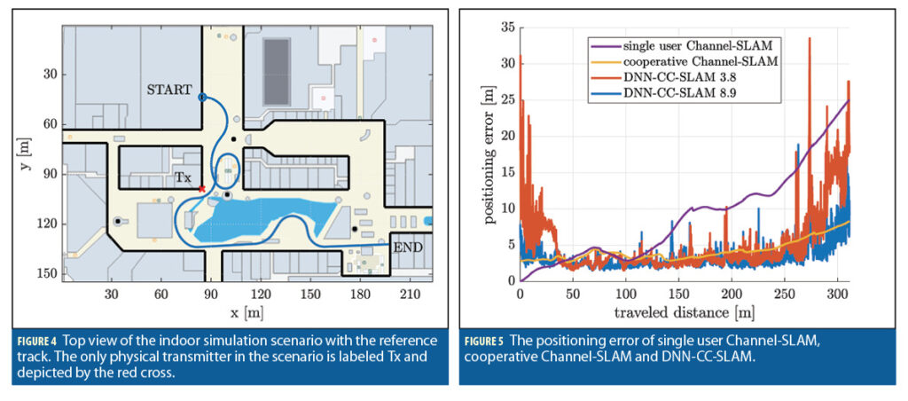
To evaluate our novel approach, we performed simulations in an indoor scenario with a single physical transmitter. A top view of the scenario is depicted in Figure 4. The physical transmitter is labeled Tx and depicted by the red cross. The black lines are walls representing planar surfaces, while the black dots are pillars representing point scatterers. In the scenario, a user track that we will refer to as the reference track is plotted by the blue line. The length of the reference track is 311.2m.
The physical transmitter continuously transmits a signal known to the user. This transmit signal has a constant power spectral density over the entire bandwidth of 100MHz. Its carrier frequency is at 1.9GHz. A snapshot of the received signal is sampled every 100ms at the receiver and processed by the channel estimator. The user is equipped with a rectangular antenna array of nine elements arranged in a uniform 3 × 3 grid. AoA information is used in cooperative Channel-SLAM, but not in training or evaluating the DNN. Similar to AoA information, turn rate information from a gyroscope that is rigidly mounted to the receiver is only used in the particle filter in cooperative Channel-SLAM as a control input.
At each user position, the channel impulse response (CIR) is calculated with ray tracing to obtain a received signal for the simulations. However, the users neither know the location of the physical transmitters nor have any information regarding the locations of walls and scatterers in the scenario. The initial position of the users is known in their own local coordinate system. However, the transformation parameters relating these local coordinate systems to those of other users are unknown and estimated with map matching in cooperative Channel-SLAM.
The positioning performance of a reference user going along the reference track in Figure 4 is plotted in Figure 5 in terms of the mean absolute error (MAE) for single user and cooperative Channel-SLAM and in terms of the Euclidean distance between the true and estimated positions for DNN-CC-SLAM. Due to the stochastic nature of the particle filter in Channel-SLAM and the optimization method in the DNN, all results in Figure 5 are averaged over 100 runs.
The positioning performance of single user Channel-SLAM is depicted by the purple curve for reference. The positioning error along the reference track keeps increases over time as the user keeps going to unknown areas. Only in the region around a traveled distance of 75m can we make use of loop closure as the user is going along a loop, making the positioning error decrease to some extent. Note that in single user Channel-SLAM, no map matching is performed and the user is in their own local coordinate system. Accordingly, the positioning error is the error within that local reference system and is zero at the beginning of the track.
The yellow curve depicts the positioning error for the cooperative Channel-SLAM case along the reference track, where 21 different users have contributed to a prior map. To create this map, these 21 users went on different trajectories through the scenario in Figure 4 with a total traveled distance of 3.8km. The positioning error of cooperative Channel-SLAM converges in the order of approximately 4m for the most part. The error increases to some extent only toward the end of the track, where the geometry regarding the positions of the transmitters relative to the user is unfavorable.
The red curve labeled DNN-CC-SLAM 3.8 shows the error curve for DNN-CC-SLAM, where the training data for the DNN is obtained from the same 21 users that have contributed to the prior map in the cooperative Channel-SLAM case. For training and evaluating the DNN, the SFLSE is used as a channel estimator.
To further evaluate DNN-CC-SLAM, we simulated another 5.6km of synthetic trajectories with cooperative Channel-SLAM corresponding to a further 23 users. Overall, this leads to 8.9km of trajectories of 44 different users. The blue curve labeled DNN-CC-SLAM 8.9 shows the error curve for DNN-CC-SLAM with the data from the 8.9km of traveled distance from these 44 users used as training data for the DNN. As expected, the positioning error decreases with the additional 5.6km of training data, in particular in areas with a high error.
The positioning error averaged over the entire track is 9.0m for the single user Channel-SLAM case, 5.2m for DNN-CC-SLAM with 3.8km of training data and 4.2m for both cooperative Channel-SLAM and DNN-CC-SLAM with 8.9km of training data. The average positioning error of DNN-CC-SLAM is thus 24% times higher than that of cooperative Channel-SLAM for the same amount of training data. To get to the same performance as cooperative Channel-SLAM, DNN-CC-SLAM needs 2.3 times more training data.
DNN-CC-SLAM, however, is a snapshot-based method and thus does not make use of temporal or spatial correlations, which the particle filter in the Channel-SLAM cases inherently does when tracking the user. The DNN-CC-SLAM error curves are therefore very volatile, while the Channel-SLAM error curves are very smooth. Incorporating such correlations at neighboring time instants is part of our ongoing work. We expect this will improve the positioning performance of DNN-CC-SLAM considerably.
Conclusion
Traditional fingerprinting schemes suffer from the drawback of the tedious collection of fingerprints at known locations in the offline phase. When the environment changes, fingerprints may have to be collected again. The high effort of collecting fingerprints may be a crucial impairment for such schemes.
In our novel approach named DNN-CC-SLAM, we combine a SLAM scheme with fingerprinting. In cooperative Channel-SLAM, multiple users estimate their location based on the channel impulse response using virtual transmitters, and channel parameters are estimated as nuisance parameters. In the offline phase stage of DNN-CC-SLAM, these nuisance parameters and the estimated user positions are used for training a DNN. In the online stage, users can exploit the trained DNN to estimate their position. While cooperative Channel-SLAM suffers from a high computational complexity, the online phase in DNN-CC-SLAM is crucially less complex, while the positioning performance is in the same order of magnitude as for cooperative Channel-SLAM.
Acknowledgments
This article is based on material presented in a technical paper at ION GNSS+ 2022, available at ion.org/publications/order-publications.cfm
References
(1) K. Witrisal, P. Meissner, E. Leitinger, Y. Shen, C. Gustafson, F. Tufvesson, K. Haneda, D. Dardari, A. F. Molisch, A. Conti, and M. Z. Win, “High Accuracy Localization for Assisted Living – 5G Systems will turn Multipath Channels from Foe to Friend,” IEEE Signal Process. Mag., vol. 33, no. 2, pp. 59–70, Mar. 2016.
(2) H. Wymeersch, N. Garcia, H. Kim, G. Seco-Granados, S. Kim, F. Wen, and M. Frohle, “5G mm Wave Downlink Vehicular Positioning,” in¨ IEEE Global Communications Conference (GLOBECOM), Dec. 2018, pp. 206–212.
(3) R. Mendrzik, F. Meyer, G. Bauch, and M. Win, “Localization, Mapping, and Synchronization in 5G Millimeter Wave Massive MIMO Systems,” in 2019 IEEE 20th International Workshop on Signal Processing Advances in Wireless Communications (SPAWC), 2019, pp. 1–5.
(4) M. Ulmschneider, C. Gentner, and A. Dammann, “Cooperative Estimation of Maps of Physical and Virtual Radio Transmitters,” in Proceedings of 34th International Technical Meeting of the Satellite Division of the Institute of Navigation (ION GNSS+ 2021), Sep. 2021.
(5) M. Ulmschneider, C. Genter, and A. Dammann, “Entropy of Transmitter Maps in Cooperative Multipath Assisted Positioning,” in IEEE International Conference on Communications (ICC) Workshops, 2022.
(6) A. Khalajmehrabadi, N. Gatsis, and D. Akopian, “Modern WLAN Fingerprinting Indoor Positioning Methods and Deployment Challenges,” IEEE Commun. Surveys Tuts., vol. 19, no. 3, pp. 1974–2002, 2017.
(7) L. Xiao, A. Behboodi, and R. Mathar, “A Deep Learning Approach to Fingerprinting Indoor Localization Solutions,” in 27th International Telecommunication Networks and Applications Conference (ITNAC), Nov 2017, pp. 1–7.
(8) X. Liu, J. Cen, Y. Zhan, and C. Tang, “An Adaptive Fingerprint Database Updating Method for Room Localization,” IEEE Access, vol. 7, pp. 42626– 42638, 2019.
(9) Z. Liu, X. Luo, and T. He, “Indoor Positioning System Based on the Improved W-KNN Algorithm,” in IEEE 2nd Advanced Information Technology, Electronic and Automation Control Conference (IAEAC), March 2017, pp. 1355–1359.
(10) K. S. Kim, S. Lee, and K. Huang, “A scalable deep neural network architecture for multi-building and multi-floor indoor localization based on Wi-Fi fingerprinting,” Big Data Analytics, vol. 3, no. 1, Apr. 2018.
(11) T. Jost, W. Wang, U. Fiebig, and F. Perez-Fontan, “Detection and Tracking of Mobile Propagation Channel Paths,” IEEE Trans. Antennas Propag., vol. 60, no. 10, pp. 4875–4883, Oct. 2012.
(12) M. Ulmschneider and C. Gentner, “RANSAC for Exchanging Maps in Multipath Assisted Positioning,” in IEEE International Conference on Industrial Cyber Physical Systems (ICPS), 2019.
(13) M. Ulmschneider, “Cooperative Multipath Assisted Positioning,” Ph.D. dissertation, Hamburg University of Technology, 2021.
(14) T. L. Hansen, B. H. Fleury, and B. D. Rao, “Superfast Line Spectral Estimation,” IEEE Trans. Signal Process., vol. 66, no. 10, pp. 2511–2526, May 2018
Authors
Markus Ulmschneider studied communications and computer engineering at the University of Ulm, Germany, from where he received his bachelor’s degree in 2011 and his master’s degree in 2014. In 2021, he received his PhD (Dr.-Ing.) from the Hamburg University of Technology. In 2014, he joined the Institute of Communications and Navigation of the German Aerospace Center (DLR), Germany, where he has been part of the scientific staff of the Mobile Radio Transmission group. His main research interests include multipath assisted positioning as well as multi-sensor localization, machine learning and signal processing.
Christian Gentner received the Dipl. Ing. (BA) degree in electrical engineering, focusing on the main topic of communication technology, from the University of Applied Science Ravensburg-Weingarten, in 2006, and the M.Sc. and Dr. Ing. (Ph.D.) degrees in electrical engineering from the University of Ulm, in 2009 and 2018, respectively. During his BA study, he received practical experience at Rohde & Schwarz in Munich. Since 2009, he has been working at the Institute of Communications and Navigation, German Aerospace Center (DLR). His current research focuses on indoor positioning.
Armin Dammann received the Dipl.-Ing. (M.Sc.) and Dr.-Ing. (Ph.D.) degrees in Electrical Engineering from the University of Ulm, Germany, in 1997 and 2005 respectively. In 1997, he joined the Institute of Communications and Navigation of the German Aerospace Center (DLR) as a research staff member. Since 2005 he has been head of the Mobile Radio Transmission Research Group. His research interests and activities include signal design and signal processing for terrestrial wireless communication and navigation systems. In these fields, he has been active in several EU-projects, e.g., WINNER, WHERE and WHERE2. Dammann is a lecturer at the Technical University of Munich for “Robot and Swarm Navigation.”


