
Difficult GNSS environments and adverse weather conditions require a fusion of many sensors to maintain lane-level accuracy for autonomous platforms, without incurring high costs that would inhibit widespread adoption. Radars are an attractive option in a multi-sensor integration scheme due to being robust to adverse weather and insensitive to lighting variations.
The multi-radar integrated version of AUTO uses inertial navigation, real-time kinematic GNSS, odometer, and multiple radar sensors with high-definition maps in a tight non-linear integration scheme. AUTO can reliably produce accurate and high-rate navigation outputs in real-time and under all urban environments. Key performance indices during simulated GNSS outages quantify the accuracy of the solution for prolonged periods.
DYLAN KRUPITY, ABDELRAHMAN ALI, BILLY CHAN AND MEDHAT OMR, TRUSTED POSITIONING INC.
JONATHAN PREUSSNER AND ARUNESH ROY, UHNDER INC.
JACQUES GEORGY AND CHRISTOPHER GOODALL, TRUSTED POSITIONING
Solving the localization problem is a crucial step in enabling the development of autonomous platforms. To achieve high levels of autonomous driving, the positioning solution must be highly accurate, precise, reliable in all environments, and always available. This presents a challenge in areas where GNSS signals may be degraded or denied. Achieving autonomy will have a wide range of safety, social and economic benefits.
Sensor fusion, for example integrating GNSS with inertial navigation systems (INS) and odometry, can make use of the complementary strengths and weaknesses of different sensors, providing the best solution given all available measurements. Real-time kinematic (RTK) GNSS is a valuable and accurate source of information, providing up to centimeter level absolute position updates in areas with reliable RTK coverage. However, GNSS still suffers from multipath and occlusions in deep urban canyons, underground parkades, and tunnels. INSs are always available as fully self-contained sensors, and provide high-rate solutions, over 100 Hz, but drift over time. This is especially significant for low-cost micro-electromechanical systems (MEMS) based sensors, GNSS updates can correct for these errors, while the INS can bridge GNSS gaps. Unfortunately, in harsh urban environments, the extended periods of signal degradation or unavailability of GNSS makes it very challenging to maintain lane-level positioning. As a result, perception sensors are being explored as another independent source of information that can be integrated into the fusion stack. Common perception sensors include cameras and lidar. They can provide detailed information of a scene, which is very useful for object detection or map matching. However, cameras are affected by poor lighting from backlit objects and scenes, and adverse weather is a weakness of both sensors.
Radar does not suffer from these inherent weaknesses and can provide reliable measurements regardless of weather conditions. The drawback of radar, particularly from a map-matching perspective, is the sparseness of the data and a lower angular resolution than that of lidar. Recent advances in technology have mitigated some of these limitations, making radar a viable option for localization. State-of-the-art imaging radars can produce high-resolution information at long range on multiple dynamic targets with a high update rate, even in a cluttered scene. The measurements are in a 4D domain that includes range, doppler, azimuth, and elevation.
AUTO consists of the fusion of INS, GNSS, odometer, and radar with high-definition (HD) maps in a tightly integrated solution to provide lane-level accuracy. AUTO software flexibly supports multi-radar configurations to achieve up to 360-degree horizontal coverage of a scene to enhance the positioning accuracy. In addition to using the radar system for localization, radar mapping is also possible when using crowd-sourcing techniques.
AUTO is a real-time integrated navigation system that provides an accurate, reliable, high-rate, and continuous (always available) navigation solution for autonomous vehicles and robotic platforms. The software leverages several patents in its tight non-linear integration scheme to fuse information from multiple imaging radars with the INS/GNSS/odometer solution.
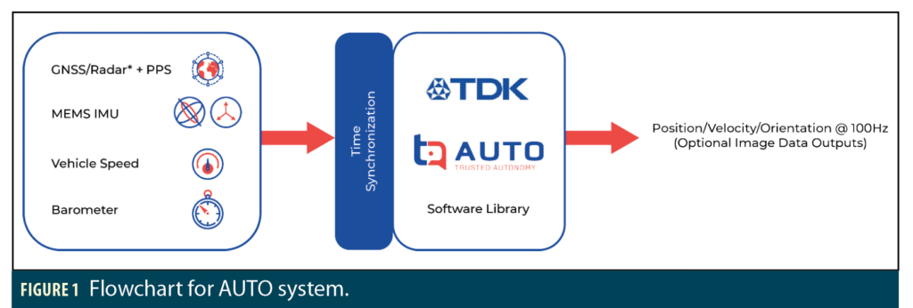
INS is always available and supports a high-rate output of 100 Hz. Furthermore, MEMS-based sensors can be obtained at affordable prices with high volume availability. Based on these benefits, INS is used as the core for AUTO navigation. Figure 1 shows an overview of the AUTO system and the input information. Accurate system-level time synchronization is performed to compensate for sensor latencies. Through the tight integration scheme, the AUTO solution can output a full 3D navigation solution at 100 Hz, using all available measurements to compute the best possible solution, even though some sensors have lower update rates.
AUTO provides high-accuracy and -reliability positioning at scalable cost for autonomous land-based platforms. The integrated solution can perform in a competitive manner comparable to more costly high-end systems, achieving a high-rate solution with decimeter-level accuracy under all environments and conditions. With the array of sensors and redundant information available to the system, it can also be used for integrity monitoring applications. The self-contained nature of the INS always allows the system to fall back on INS positioning in case other sensors fail. AUTO is optimized to use automotive-grade MEMS IMUs among its components:
• MEMS IMU
• High-accuracy GNSS (RTK/PPP)
• Imaging radar(s)
• Odometer/Vehicle Speed (DMI/CAN/OBD-II)
• Barometer
AUTO Sensor Fusion and Features
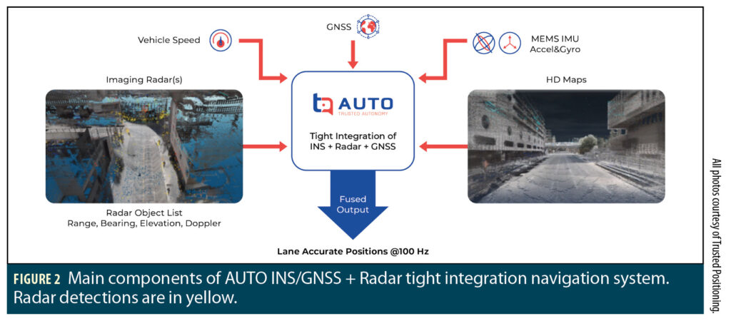
Figure 2 shows a different view of the main components of the AUTO system including fused inputs such as: IMU, GNSS, speed, HD maps, and radar detections (yellow) in a scene.
Supported speed readings may come from the on-board diagnostics (OBD-II) port, distance measuring instrument (DMI), vehicle speed sensor (VSS), or the vehicle’s CAN bus. This means the vehicle speed input to AUTO can be conveniently and economically obtained from the vehicle’s existing odometry sensors. The measured speed can be affected by various factors that include pressure, temperature, and wear. This introduces an odometer scale factor which AUTO can continuously estimate in real-time and correct for any errors in the measured speed.
AUTO can provide ego velocity information updates to each of the radars in real-time, regardless of their relative orientation with respect to the vehicle body frame or the IMU frame. The ego velocity information enables the system to get reliable radar measurements of static objects in the background. Hig- accuracy RTK GNSS and radars with HD maps provide a source of absolute positioning inputs that AUTO can use to self-calibrate. The multi-radar support enables a more feature-rich scan of the scene, improving the map-matching and localization process. In addition, AUTO uses techniques for very accurate time synchronization across all sub-systems and sensors to achieve the best possible positioning accuracy. This tightly integrated navigation solution can continuously estimate, calibrate, and correct for mounting misalignments of the inertial sensors in real-time, including roll, pitch, and heading misalignments.
Real-Time Software and Reference Design
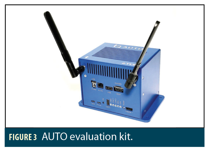
The AUTO software can process all the sensor inputs and compute the integrated solution at 100 Hz in real-time. AUTO is highly optimized to run efficiently on application processors with different operating systems. Real-time testing of the software was based on an NVIDIA Jetson AGX Xavier system which is used in the evaluation kit shown in Figure 3. It consists of an ARM Cortex A57v processor with 8GB of RAM.
Imaging Radar
To obtain the maximum benefit from radar-based localization, high resolution digital imaging radars by Uhnder are used to produce detailed scans of the environment. Uhnder offers a fully software-defined digital imaging radar on a single chip (RoC). Unlike traditional automotive radar, which uses an analog frequency modulated continuous wave (FMCW) architecture, Uhnder uses a digital code modulation (DCM) architecture with 192 virtual receive channels. This digital architecture results in 16 times better angular resolution, 24 times more power on target, and 30 times better contrast compared to analog radar, allowing it to detect objects out to 300 meters. Precise time synchronization, fine angular resolution and high-contrast resolution (HCR) are critical for localization. The digital radar detects and resolves both static and dynamic objects, whether small or large, when they are located in close proximity to each other, greatly improving positioning accuracy, reliability, and integrity across all weather conditions and environments.
Interference robustness and mitigation is an important consideration for perception sensors used for localization, especially in heavy traffic and urban environments. The number of radars is growing exponentially as new vehicles are being equipped with more advanced driver assistance systems (ADAS) and automated driving system (ADS) functions. In the DCM architecture, every transmitter is identified by one of a quintillion (1018) unique codes. This minimizes mutual interference between digital radars. Uhnder also incorporates additional interference mitigation technology into its chips to suppress impacts from traditional FMCW analog radar interference.
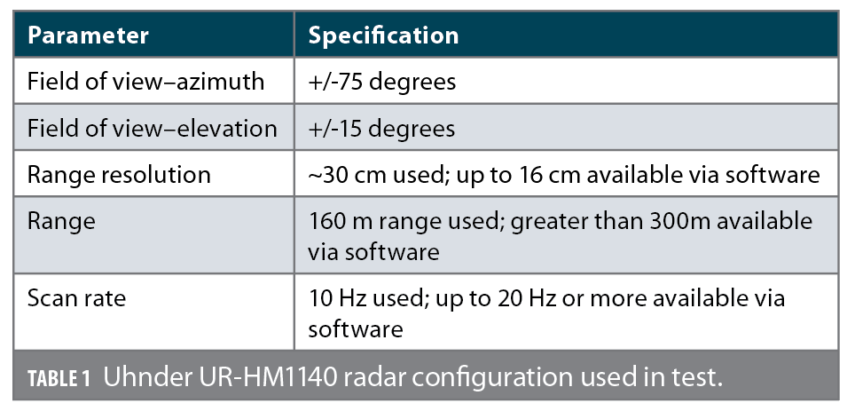
Table 1 provides a summary of the configuration and specifications for the Uhnder RoC sensor that was used for AUTO testing.

INS/GNSS + Radar Vehicle Test Setup
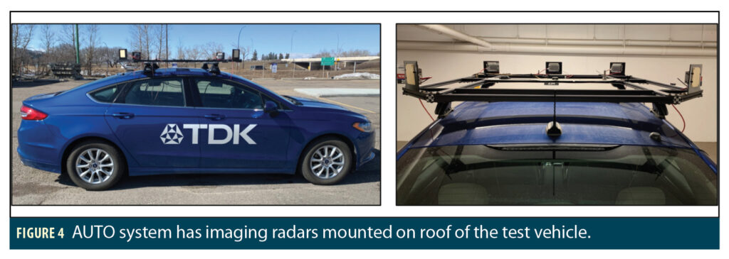
The AUTO system vehicle test setup is shown in Figure 4. Note the five imaging radars mounted to the roof of the vehicle. This configuration consists of four corner-mounted radars, plus one forward facing radar at the front. This configuration gives a combined horizontal coverage of 360 degrees, with significant overlapping horizontal field of view between the radars. The evaluation kit that contains the rest of the system hardware and components is set in the trunk of the vehicle.
Table 1. lists the radar configurations and specifications used in testing. Note that our testing used a range resolution of 30 centimeters with a range of 160 meters, although higher resolutions are available in different modes programmable by the software. The AUTO system was rigorously tested using this setup in multiple locations and seasons. This includes a variety of weather conditions, temperatures and times of day to ensure reliable and consistent performance.
The system was thoroughly tested and characterized using many different sensors to ensure reliable performance. Challenging GNSS environments considered for testing were downtown areas and urban canyons where natural outages can occur due to buildings, bridges, tunnels, and multipath. To provide statistically significant key performance indices (KPIs), simulated GNSS outages were introduced with various durations lasting up to 8 minutes.
Vehicle Positioning Results
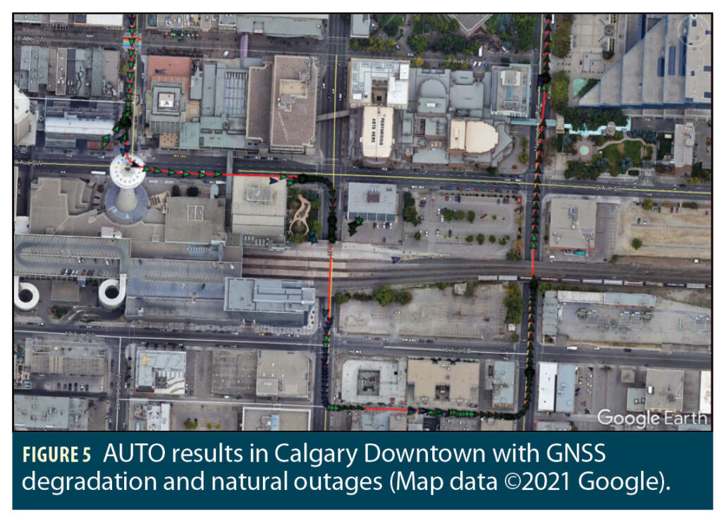
These results show the positioning accuracy of the AUTO system by displaying the navigation solutions of one or more test trajectories in Google Earth. The data in Figure 5 shows natural GNSS multipath and outages, indicated by the green arrows, due to blockages from high buildings in Downtown Calgary and due to passing under bridges.
In Figure 6, a simulated GNSS outage is introduced after the first 200 seconds. Notice how the vehicle deviated by more than 36 meters by the end of the trajectory in the INS-only solution (in blue), while the tightly integrated INS/GNSS with radar solution (in red) maintained lane-level accuracy.
Vehicle Performance Consistency Results
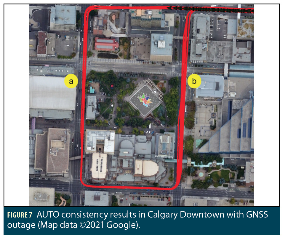
To test the system’s performance consistency, multiple groups of data were collected. Figure 7 shows the tightly integrated INS/GNSS with radar results for 15 test trajectories that were collected at different times of day and night. A simulated GNSS outage is introduced after the first 90 seconds. In this test the driver used two different lanes of the street when turning left and heading south in section “a.” When moving north in section “b” the driver takes multiple different lanes of the road.
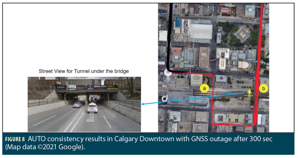
Figure 8 shows a similar test using 15 trajectories that were collected using a different route. A simulated GNSS outage is introduced after the first 300 seconds. In this test the driver used two different lanes of the street while heading south in section “a” of Figure 8. When moving north in section “b” the driver takes any one of the available north bound lanes. Note that the gap between the trajectories in section “b” occurs where the road is divided in a tunnel when passing under a bridge.
Key Performance Indices
To statistically assess the performance of the navigation solution, KPIs were computed using multiple trajectories. Simulated GNSS outage intervals are introduced with 1, 2, 4 and 8-minute durations. During the simulated outages, the GNSS solution is not passed to the AUTO system. However, the reference solution uses all the GNSS readings without any simulated outages from another instance of an AUTO processing run. This means each trajectory is run five times: using simulated outages of 1, 2, 4 and 8 minutes, plus a reference run without outages. The error is calculated between the configuration of AUTO under assessment (with outages) and the reference (without outages).
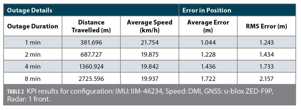
A set of three tables are shown, which present the results using a configuration of one, three and four radars. All other parameters, configurations and components are kept the same. Table 2 shows the KPI results for the AUTO integrated radar and INS/GNSS solution of a group of data collected in Downtown Calgary. In this case, the datasets use one forward facing second-generation Uhnder radar (UR-HM1140-X).
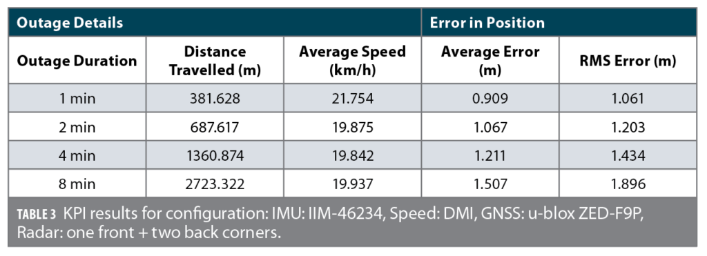
Table 3 shows the KPI results for the integrated radar and INS/GNSS solution for the same test setup, except the datasets now use a three-radar configuration, with one forward facing radar and two backward facing radars mounted on the rear corners of the vehicle. The increased combined field of view of the additional radars from this configuration yields a noticeable improvement in the positioning accuracy.
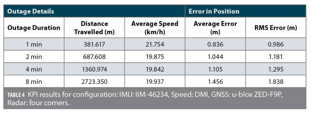
Table 4 shows the KPI results for the integrated radar and INS/GNSS solution again; this time, the datasets use a four-radar configuration consisting of four radars mounted on the corners of the vehicle. Again, an improvement in the accuracy of the solution can be observed with the additional radar.
Results for Robot
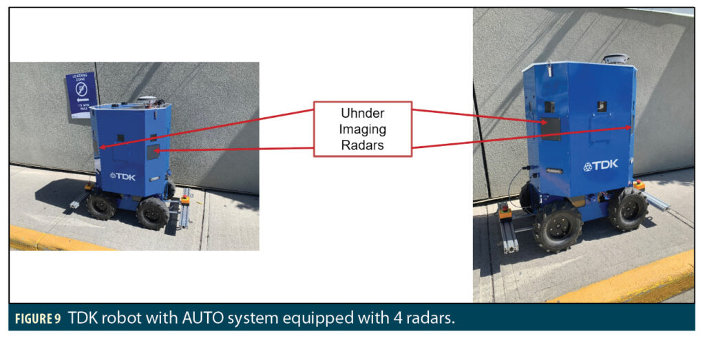
The AUTO system has also been tested and verified to work on land-based robotic platforms. The system shown uses motor encoders to obtain a speed input for AUTO. An example of the TDK robot is shown in Figure 9. GNSS antennas can be seen on the top cover of the robot. Four radars are mounted in the corners of the robot; window openings above the radars allow for video camera recording of the environment. All results for the robot presented in this article use the UR-HM1010 radar sensors from Uhnder.
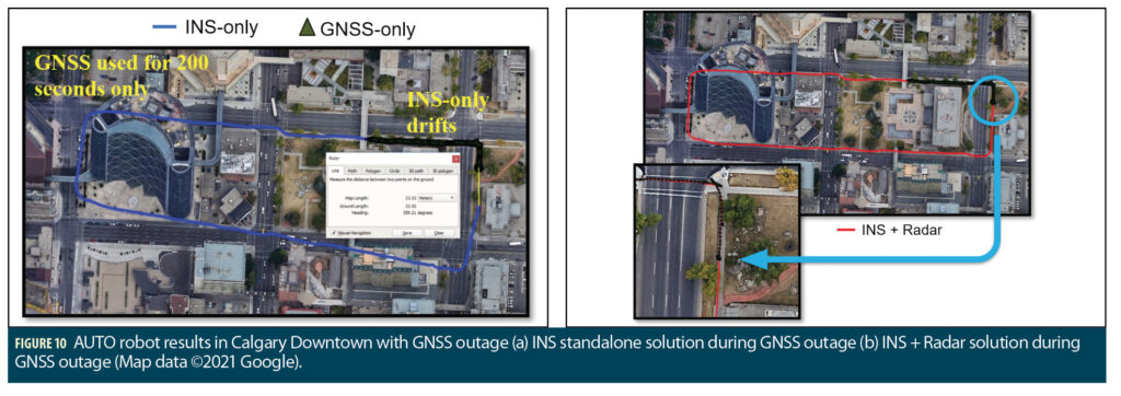
Test trajectories collected in Downtown Calgary demonstrate the lane-level positioning accuracy of the AUTO system for robot. In Figure 10, a simulated GNSS outage is introduced after the first 200 seconds. Notice how the robot deviated by more than 33 meters by the end of the trajectory in the INS-only solution (in blue), while the tightly integrated INS/GNSS with radar solution (in red) was able to maintain lane-level accuracy to successfully close the loop and maintain sidewalk-level accuracy.
Robot Performance Consistency
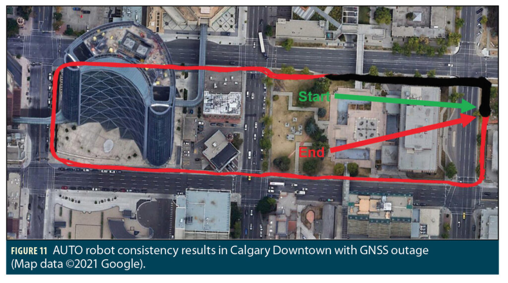
Fifteen test trajectories were collected at different times of day and night in downtown Calgary to test the consistency in performance of the AUTO solution on the robot. Figure 11 shows the tightly integrated INS/GNSS with radar results. A simulated GNSS outage is introduced after the first 200 seconds. The driver follows the same route on the sidewalk around the block in each trajectory. As can be observed, all the solutions follow the sidewalk and close the loop with the start point, despite having no GNSS updates for most of the duration.
Robot KPI
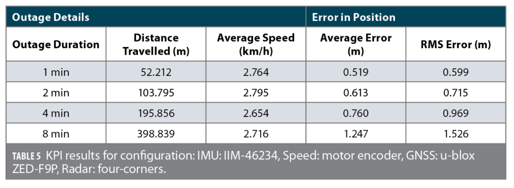
The robot results are generated using the same methodology as for the vehicle. To reiterate, simulated GNSS outages are introduced with 1, 2, 4 and 8 minute durations, and are compared against a reference solution generated without any simulated outages. Table 5 shows the KPI results for a group of data collected in downtown Calgary. In this case, the datasets used four corner mounted UR-HM1010 Uhnder radars. Even though these results are with the first-generation radar, the errors are smaller than for vehicle due to the much lower average speed and distance travelled of the robot.
HD Map Support
AUTO uses radar for localization by performing map-matching of the radar scans to a globally referenced HD map. All the results shown previously in this article used a LiDAR map based on a pre-survey of the test area in downtown Calgary. AUTO can support a variety of input map types for localization, including both 2D and 3D maps, as well as different formats such as point cloud and occupancy grid maps. However, maps are not required to be derived from a LiDAR pre-survey. With the high-resolution 4D radar imagery, AUTO can generate radar-based maps through crowdsourcing techniques using its existing sensor suite without needing LiDAR.
In this case, the INS/GNSS system is used for localization, while the radars are used for map building. The crowdsourcing makes use of multiple passes through the same survey area, preferably using different routes and different times of day to avoid occlusions and remove any non-permanent features like parked cars. The results are then aggregated to form a crowdsourced radar map. A multi-radar configuration consisting of at least three radars is especially useful for the crowdsourcing technique. Assuming a proper geometrical arrangement, a complete 360-degree horizontal field of view can be achieved for crowdsourcing. The crowdsourced maps can then be used in subsequent runs as a global reference map for localization purposes.
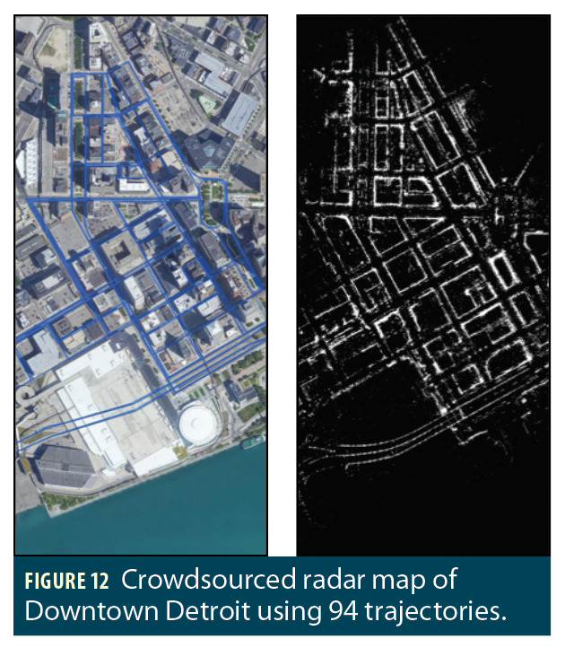
An example of a crowdsourced map of downtown Detroit is presented in Figure 12. This map was generated using a total of 94 trajectories collected over several days using a three-radar configuration (one forward-facing radar and two rear-corner radars). The streets, building walls, tunnels, and other features are clearly mapped. Note that the sparse detections for the road near the bottom left portion of the image are due to a high overpass that is not in the radar field of view in the elevation direction.
Once HD maps are crowdsourced and formed using radars, they can then be used as the HD map source for localization. This seamless process allows new areas to be mapped using the existing vehicle platforms that also perform the localization. This is especially useful for applications with new or changing environments, such as during road construction, sidewalk diversions, or for positioning vehicles within an active construction site.
Conclusion
AUTO can achieve accurate lane-level positioning in different environments, including harsh downtown areas and urban canyons, regardless of adverse weather conditions. The tight integration of radar and HD maps with INS/GNSS can provide a reliable, accurate, and continuous positioning navigation system capable of operating at 100 Hz, which is required for autonomous machine control. By leveraging multi-radar configurations, the system can make use of the expanded total horizontal field of view, thereby detecting more features and improving the positioning accuracy as compared to a single radar setup. In addition, a multi-radar configuration can provide detailed scans of the environment, enabling crowdsourcing techniques to be used to create radar-based maps for navigation. The AUTO system was shown to maintain lane-level and sidewalk-level positioning even during extended GNSS outages, demonstrating the potential for such a tight integration system for both vehicle and robotic platforms for a variety of applications.
Manufacturers
The following are suggested automotive-grade IMUs for AUTO (accelerometer, gyroscope): InvenSense IAM-20680—AEC-Q100; IAM-20680-HT—AEC-Q100; IAM-20685—ASIL B. Some suggestions for industrial: InvenSense IIM-46230; IIM-46234.
The AUTO evaluation kit includes: TDK InvenSense IAM-20680-HT MEMS IMU, TDK InvenSense ICP-10101 MEMS barometer, u-blox ZED-F9P GNSS receiver, Atmel ARM Cortex M4 processor.
AUTO has been intensively tested using these devices: UR-HM1010 first-generation RoC sensor, UR-HM1140-X second-generation RoC sensor; IAM-20680, IAM-20680-HT and IIM-46234 MEMS IMUs mounted in the trunk; multiple GNSS receivers: u-blox ZED-F9P, u-blox NEO-M8P, and NovAtel Flexpak6 OEM628; different speed sensors (OBDII, DMI); ICP-10101 MEMS barometer.
In Figure 5, data was collected with a Novatel-Flexpak6-OEM628 GNSS receiver, IAM 20860 IMU, DMI for speed source, and one forward facing first-generation Uhnder radar (UR-HM1010).
Figures 6 and 7 show data from a u-blox ZED-F9P GNSS receiver, IIM 46234 industrial grade IMU, DMI for speed source, and one forward facing first-generation Uhnder radar
Figure 8 used the above suite and five UR-HM1140-X Uhnder radars.
Figures 10 and 11 used the u-blox NEO-M8P GNSS receiver, IAM-20680 IMU, motor encoder for speed source, and four UR-HM1010 Uhnder radars.
Authors
Dylan Krupity is a software designer at Trusted Positioning Inc., a TDK Group Company. He received his B.Sc. in geomatics engineering from the University of Calgary, Canada.
Abdelrahman Ali is a software algorithms manager at Trusted Positioning. He received his interdisciplinary Ph.D. in geomatics engineering and electrical and computer engineering from the University of Calgary.
Billy Chan is a software designer at Trusted Positioning. He received an M.Sc. in geomatics engineering from the University of Calgary.
Medhat Omr is a software algorithms manager at Trusted Positioning. He received an Ph.D. in electrical and computer engineering from Queens University, Canada.
Arunesh Roy serves as Uhnder’s senior director for advanced applications and perception.He earned his doctorate degrees in electrical engineering from Wright State University.
Jonathan Preussner is a radar applications engineering manager at Under. He received his M.S. degree in electrical engineering from the University of Florida.
Jacques Georgy is the senior director of navigation R&D at Trusted Positioning. He received his Ph.D. degree in Electrical and Computer Engineering from Queen’s University.
Christopher Goodall
is the co-founder, managing director and president of Trusted Positioning. He has a Ph.D. in geomatics engineering from the University of Calgary.


