
Leveraging tight coupling of GNSS with terrestrial radionavigation and inertial sensing provides robust PVT for unmanned aerial vehicles, but additional layers will be required for autonomous UAM.
ROBERT TENNY, TODD E. HUMPHREYS, UNIVERSITY OF TEXAS AT AUSTIN
Central to the transportation revolution that will be driven by urban air mobility (UAM) is the problem of robust and secure navigation. Urban environments offer more challenges, such as interference and multipath, when compared to open-sky conditions. As the only positioning system that offers absolutely-referenced meter-level accuracy with global coverage, GNSS will no doubt play a significant role in this revolution. If strengthened against jamming and spoofing, carrier-phase-differential GNSS (CDGNSS), coupled with low-cost inertial sensing, will be nearly sufficient for position, velocity and timing (PVT) needs. But nearly sufficient is insufficient: It is not enough for a UAM PVT solution to offer decimeter-accurate positioning with 99% availability, or even 99.9% availability. UAM will demand that its navigation systems offer decimeter-accurate positioning with integrity risk on the order of 10-7 for a meter-level alert limit and availability with several more 9s than 99.9% [1-4].
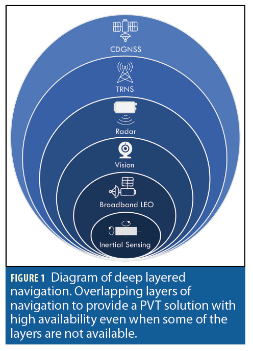
The technique proposed in this article is best viewed as one part of a comprehensive navigation solution concept called deep-layered navigation (DLN) in which synergistic but independent navigation systems are layered to increase accuracy and robustness (Figure 1). At DLN’s core sits redundant inertial navigation, which is virtually impervious to radio frequency (RF) interference, poor weather, signal blockage, and data ambiguity. The outermost layer—the default navigation system and first line of defense—is a specialized variant of inertially-aided CDGNSS, recently developed in [5, 6], that has been substantially secured against spoofing and substantially hardened against the multipath and signal blockage conditions of the urban ground vehicle environment, which can be considered a worst-case realization of the urban air vehicle environment. But despite its coupling with inertial sensing, the technique developed in [5] cannot tolerate extended GNSS outages. A secondary source of absolute PVT is required to bound the growth of position errors.
A terrestrial radionavigation system (TRNS) is the second line of defense in the DLN concept, and the current focus. Its pseudorange measurements to surrounding beacons are independent of, but fully interchangeable with, GNSS measurements. TRNS beacons provide much stronger signals compared to GNSS, operate at a different frequency, and offer a full absolutely-referenced backup PVT solution to GNSS. In particular, we explore tight coupling with NextNav’s Metropolitan Beacon System (MBS). MBS is particularly attractive for UAM because its signals carry not only wideband (multipath-resistant) synchronization sequences for ranging, but also corrections data for barometric altitude determination and for CDGNSS.
The development of a tightly-coupled GNSS-TRNS-inertial PNT system is a prelude to upcoming work on comprehensive deep-layered navigation for UAM, including additional layers based on radar localization, visual odometry and LEO-satellite-provided GNSS.
Related Work
Augmentation of GNSS with terrestrial signals has been explored and shown to provide an added benefit over exclusive use of GNSS [7, 8]. But these techniques were demonstrated only on ground vehicles, and the sensor integration with CDGNSS was not tightly-coupled, so the terrestrial signals were not incorporated in a way that permitted aiding of the ambiguity resolution process critical to CDGNSS. Loose coupling between GNSS and TRNS has been used to augment GNSS and provide an increase in both accuracy and availability on unmanned aerial vehicles, or UAS [9-11]. But these methods fuse standard GNSS, not CDGNSS, with TRNS, and thus lack the decimeter accuracy that will be desirable, if not required, for UAM. Relative ranging measurements from ultra-wide band (UWB) systems have been used to constrain integer ambiguities in CDGNSS and improve accuracy even with degraded GNSS reception [12]. Although UWB systems provide adequate performance, the limited range of the UWB signal makes it an unfavorable choice for UAM. Fusion of GNSS and signals of opportunity has been explored for aerial vehicles with promising results [13,14]. But for a safety-of-life application like UAM, it is likely that signals of opportunity will be viewed less favorably than a dedicated TRNS as a secondary means of navigation.
This article makes four primary contributions. First, it presents and demonstrates the first use of tightly-coupled CDGNSS, TRNS and inertial sensing to provide a secure and robust PVT solution. Second, it develops a novel innovations-based measurement exclusion technique that mitigates the impact of GNSS and TRNS multipath errors and pressure anomalies. Third, it offers a comparative analysis of loose and tight coupling on a UAS in an environment where only TRNS signals are available. Fourth, we perform a study of error growths during periods of GNSS denial to determine whether PVT requirements for UAM could be met despite extended intervals of GNSS denial.
Measurement Models
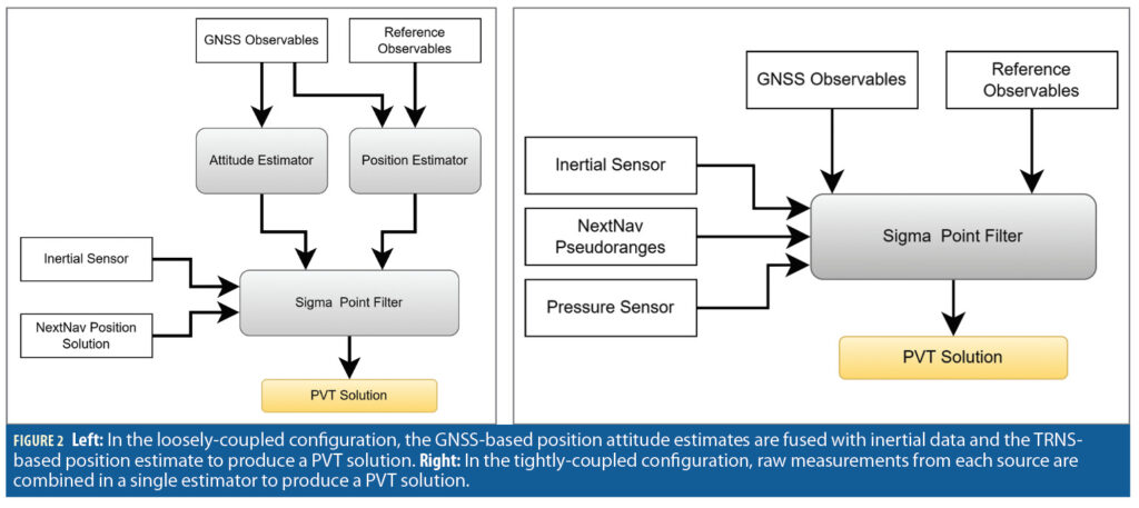
In the loosely-coupled case, the TRNS measurement is the position determined by the TRNS receiver. In the tightly-coupled case, the TRNS measurements are pseudorange and altitude derived from barometric pressure. The measurements are fused with inertial sensing data and GNSS position and attitude solutions (loosely-coupled) or raw GNSS observables (tightly-coupled). Models for the inertial and GNSS measurements may be found in [5, 16].
Loose Coupling
The position measurement zlc(k) at time k from the TRNS receiver is modeled as containing the true position xlc(k), a bias from the true position blc(k), and white Gaussian measurement noise blc(k):

The position bias blc(k), is modeled as a mean-reverting Ornstein–Uhlenbeck (OU) process with white Gaussian noise vlc(k):

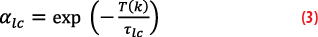
The term αlc determines how quickly the process reverts to zero. The mean reversion is governed by the time step T(k)= t(k+1)-t(k) and the time constant τlc of the exponential decay:
Tight Coupling
The TRNS pseudoranges and barometric-pressure-based altitude measurements are used in the tightly-coupled model. The TRNS pseudorange to transmitter i at time k, is modeled as including the true range to the TRNS transmitter ρi(k), the receiver clock offset between the receiver clock and GPS time δtrx(k), the transmitter clock offset δti(k), multipath error mi(k), and white Gaussian measurement noise wi(k):

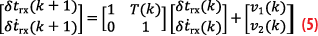
The receiver clock is modeled as a temperature-compensated crystal oscillator (TCXO) with the two-parameter clock model given in [15]. The receiver clock offset δtrx(k) evolves in time based on the clock offset rate δt⋅rx(k), time step T(k), and noise v(k):
The receiver clock offset noise v(k) is assumed to be zero mean with a variance that is a function of two parameters, h0 and h-2, related to the asymptotes of the Allan variance of the receiver clock [15]:


The TRNS transmitter clocks are disciplined by a GNSS receiver to keep them close to GPS time, but a small offset remains. The offset between the ith transmitter’s clock and GPS time, δti(k), is modeled as a mean-reverting OU process with αtx being modeled as in Equation 3, but having a unique time constant τtx to match the behavior of the transmitter clock offsets.


The TRNS receiver measures altitude using a barometric pressure sensor that is calibrated over the MBS network using information from NextNav’s weather stations. The calibration does not occur continuously; rather, it is only updated once per day. The long update interval allows for pressure biases to accumulate due to short-term changes in temperature, pressure or other changes in weather. The altitude measurement at time k, zp(k), is modeled as containing the true altitude xp(k), a bias bp(k), and white Gaussian measurement noise wp(k):

The measurement bias is modeled as an OU process with white Gaussian noise vp(k) and with αp is modeled according to Equation 3, with a unique time constant τp that is selected to model the pressure sensor errors:


Estimator States
The sensor fusion incorporates the measurement models of the TRNS measurements into the Radionavigation Laboratory’s (RNL) precise positioning engine, called PpEngine [5, 16, 17]. The positioning engine was constructed in two versions. The first version loosely couples the GNSS and TRNS measurements with the inertial sensor measurements (Figure 2). The second tightly couples the GNSS and TRNS measurements with the inertial sensor measurements (Figure 2).
It will be convenient to define the following reference frames:
u: The IMU frame is centered at and aligned with the IMU accelerometer triad.
b: The body frame has its origin at the phase center of the aerial test vehicle’s primary GNSS antenna. Its x axis points toward the phase center of the secondary antenna, its y axis is aligned with the boresight vector of the primary antenna, and its z axis completes the right-handed triad.
w: The world frame is a fixed geographic East-North-Up (ENU) frame, with its origin at the phase center of the reference GNSS antenna, which is located at a fixed base station with known coordinates.
Both the loosely- and tightly-coupled estimator states are an augmented version of the original PpEngine state containing the aerial vehicle’s position in the world frame rkw, velocity in the world frame vkw, attitude expressed as Euler error angles between the body frame and the world frame e, accelerometer bias in the IMU frame bau , and gyro bias in the IMU frame bgu :

Loosely-Coupled Estimator
The loosely-coupled implementation of PpEngine determines the aerial vehicle’s state (Equation 16) by cascading multiple estimators (Figure 2). The CDGNSS position of the primary GNSS antenna is determined using the double differenced pseudoranges and carrier phase measurements from the aerial vehicle’s primary GNSS antenna and the reference receiver [17]. A separate position measurement is determined by the TRNS receiver, and its fixed position relative to the phase center of the aerial vehicle’s primary GNSS antenna. Next, the two-dimensional attitude of the UAS is estimated using the double differenced pseudoranges and carrier phase measurements between the two GNSS antennas and the known baseline between the antennas [17]. In addition, a position and attitude estimate is determined using the measurements from the inertial sensor. These separate position and attitude solutions and their estimated covariance are cascaded into a second level estimator to produce the complete position and attitude solution (Equation 16) with the state augmented to include the TRNS position bias blcw.

Tightly-Coupled Estimator
The tightly-coupled version of the PpEngine incorporates all the sensor measurements directly into a single estimator (Figure 2). The single estimator is used to determine the state [5,18]. The estimator state (Equation 17) was augmented by including estimates of the TRNS receiver clock offset δtrx, TRNS receiver clock offset rate δt⋅rx, transmitter clock offsets for n transmitters δti,…,δtn}, and pressure sensor offset bpw.

Estimating the clock parameters for both the local clock and transmitter clock from the pseudorange measurements is not fully observable. However, the local clock offset can be separated from the transmitter clock offsets stylistically. The errors that are constant across all transmitters will show up in the local clock offset. Any errors that are unique to one transmitter will appear in the clock offset of that transmitter.
The transmitter clock offsets are being estimated despite not being fully observable, because the addition of a second TRNS receiver would allow for the transmitter clock offset to be observable. If two UAM vehicles each had their own TRNS receiver, the vehicles would be able to jointly estimate the TRNS transmitter clock parameters. This would make the TRNS transmitter clock offsets observable for any UAM network operating two or more vehicles.
Innovations Testing
The tightly-coupled PpEngine preforms outlier exclusion to reject TRNS measurements that may be affected by multipath and pressure measurements anomalies. The outliers are detected by preforming a hypothesis test on the TRNS pseudorange innovations and the pressure sensor innovations. The normalized innovation squared (NIS) (Equation 18)at time k is found by normalizing the innovation ν(k) with the innovation covariance S(k).

The NIS is distributed as Chi squared with nz degrees of freedom, where nz is the number of measurements at epoch k. The NIS can be used as a test statistic in a hypothesis test with ν the threshold that yields the chosen probability of false alarm PF.

Data Collection
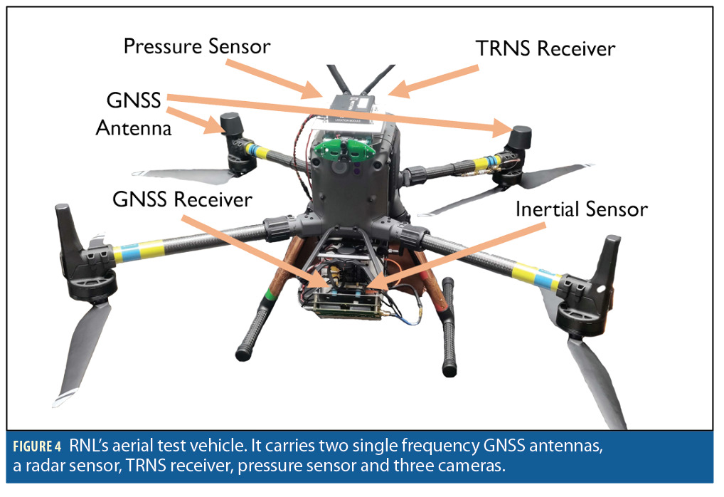
A dataset was collected using the UT RNL aerial test vehicle (Figure 4). The UAS is a multi-rotor vehicle with a mounted sensor. The sensors used in this dataset are a dual antenna GNSS L1 receiver, a NextNav TRNS receiver, and a Bosch BMX055 consumer grade inertial measurement unit (IMU). In addition, a GNSS reference receiver was placed near the planned flight location. The dataset contains dual antenna GNSS L1 double differenced pseudoranges, carrier phase measurements, TRNS position solution, TRNS pseudoranges, calibrated barometric pressure sensor measurements, and inertial sensor measurements. The reference and aerial test vehicle GNSS receivers used the RNL’s RadioLynx, GNSS front end with a 5 MHz bandwidth, and was processed with the PpRx software-defined GNSS receiver [16, 19-22].
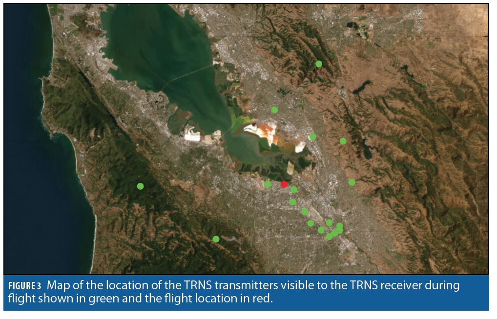
A data collection flight was performed in an area where NextNav TRNS signals are available (Figure 3). The flight path was limited to 80 meters by 100 meters in the east and north directions due to constraints on communication range with the aerial vehicle. FAA regulations limited the altitude ceiling to 121 meters above ground level. The recorded dataset includes approximately 900 seconds of data at different altitudes and varying vehicle velocities.
Results
The following section presents an analysis of the TRNS pseudoranges and an evaluation of the loosely- and tightly-coupled implementations of the position estimator.
Analysis of TRNS Pseudoranges
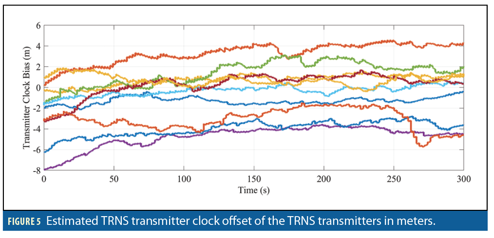
The TRNS pseudoranges were analyzed using the collected dataset and the tightly-coupled version of the PpEngine. The estimated TRNS transmitter clock offsets (Figure 5) were observed to determine the behavior of the TRNS transmitter clocks. The estimated transmitter clock offsets were found to be non-zero and unique to each transmitter. The largest difference between transmitter clock offsets indicates the transmitter clocks differ by as much as 30 nanoseconds. These estimated TRNS transmitter clock offsets are not fully observable meaning part of the estimate may be due to the TRNS receiver clock offset.
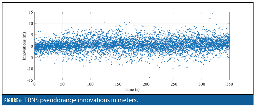
The TRNS pseudorange innovations (Figure 6) were examined and found to be nearly zero-mean and white, demonstrating that the pseudorange errors were well modeled. This shows that despite the lack of full observability of the clock offsets, the location of the TRNS receiver can be estimated.
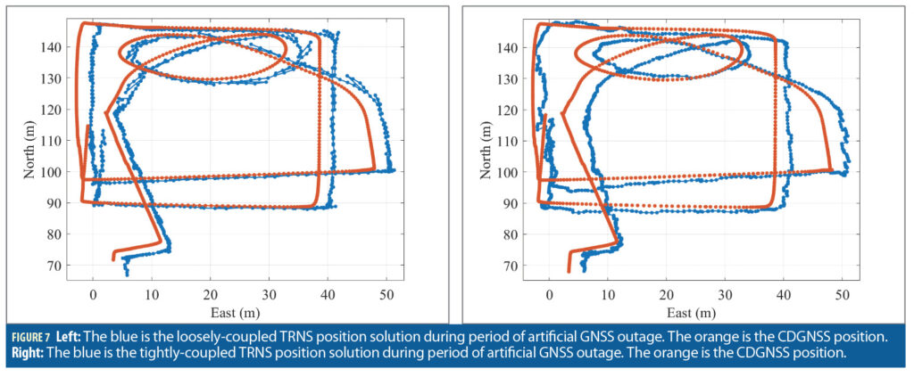
Artificial GNSS Outage
A long scale GNSS outage experiment was preformed to represent a worst-case scenario of a full loss of GNSS availability. The experiment was performed for both loosely- and tightly-coupled estimators. The loosely-coupled solution (Figure 7) shows that during a long duration GNSS outage a bias between the CDGNSS position and TRNS position arises. During this outage, the estimated error standard deviation was 1 meter in both the east and north directions.
The experiment was repeated using the tightly-coupled estimator (Figure 7).
During the outage the estimated error standard deviation was 2 meters in both the east and north directions. The tightly-coupled estimator has a similar offset from the CDGNSS position solution showing there is an unknown source of error in the TRNS network causing the offset of the TRNS position solution.
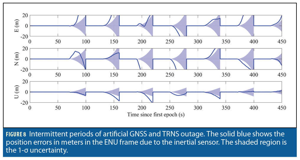
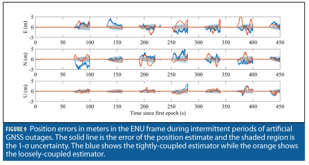
Intermittent Artificial GNSS Outages
A UAM vehicle will likely only face interference or a loss of GNSS availability for a portion of the flight during takeoff and landing while it is experiencing multipath from tall buildings. To replicate a similar situation, a test of intermittent GNSS availability was performed by artificially suppressing GNSS measurements from entering the estimator for a duration of 30 seconds with a 60 second period. A baseline performance was evaluated by testing the position estimator during a series of intermittent GNSS outages without the addition of the TRNS measurements (Figure 8).
During a GNSS outage when no TRNS signals are present, the error growth in the position was found to be exponential (Figure 8). The exponential error growth was caused by drift in the consumer grade inertial sensor. A higher grade of inertial sensor would reduce the rate of error growth; however, the error growth would still be exponential. During the short duration outage (Figure 8) the 1-σ uncertainty grew to 28 meters in the east and north directions, and 8.4 meters in the up direction. The maximum error during the test was found to be 166.7 meters, demonstrating the need for the addition of TRNS to constrain the error growth during GNSS outages.
The loosely-coupled estimator 1-σ error uncertainty grew to 1 meter in each direction. In contrast, the tightly-coupled estimator 1-σ error uncertainty grew to 1.5 meters in the east and north directions while only growing to 1 meter in the up direction (Figure 9). The tightly-coupled estimator must determine the position as well as the transmitters’ clock bias causing an overall larger uncertainty for the tightly-coupled error covariance estimate. Both estimators had very similar behavior in the up direction because of poor vertical dilution of precision causing the position estimate in the up direction to be heavily weighted by the pressure measurements.
Conclusion
Fusion of TRNS measurements with GNSS and inertial sensing constrained the error growth of the position estimate during GNSS outages. The demonstrated method of tightly-coupled CDGNSS, TRNS and inertial sensing provides a robust PVT solution on an aerial vehicle. The resilience to adverse conditions was further improved by using an innovations-based measurement exclusion technique that mitigates the impact of TRNS multipath errors and pressure anomalies. A comparative analysis of loose and tight coupling TRNS measurements during simulated GNSS outages demonstrated that during short duration GNSS outages the 1-σ position error in the east and north directions were 1 meter and 1.5 meters for the loosely- and tightly-coupled estimators, respectively. The results demonstrated that TRNS is an effective layer in DLN but additional layers of navigation will be needed to provide the fully robust centimeter accurate position required for UAM vehicles to operate autonomously in urban areas.
Acknowledgements
Research support was provided by the U.S. Department of Transportation (USDOT) under the University Transportation Center (UTC) Program Grant 69A3552047138 (CARMEN) and by NextNav, an affiliate of the 6G@UT center within the Wireless Networking and Communications Group at The University of Texas at Austin.
This article is based on material presented in a technical paper at ION GNSS+ 2022, available at ion.org/publications/order-publications.cfm.
References
- • Enge, P., “Local area augmentation of GPS for the precision approach of aircraft,” ProceedingsoftheIEEE, Vol. 87, No. 1, 1999, pp. 111–132.
- Green, G. N. and Humphreys, T., “Position-Domain Integrity Analysis for Generalized Integer Aperture Bootstrapping,” IEEE Transactions on Aerospace and Electronic Systems, Vol. 55, No. 2, 2018, pp. 734–746.
- Reid, T. G., Houts, S. E., Cammarata, R., Mills, G., Agarwal, S., Vora, A., and Pandey, G., “Localization Requirements for Autonomous Vehicles,” SAE International Journal of Connected and Automated Vehicles, Vol. 2, No. 12-02-03-0012, 2019, pp. 173–190.
- Torens, C., Volkert, A., Becker, D., Gerbeth, D., Schalk, L., Garcia Crespillo, O., Zhu, C., Stelkens-Kobsch, T., Gehrke, T., Metz, I. C., et al., “HorizonUAM: Safety and Security Considerations for Urban Air Mobility,” AIAA Aviation 2021 Forum, 2021, p. 3199.
- Yoder, J. E. and Humphreys, T. E., “Low-Cost Inertial Aiding for Deep-Urban Tightly-Coupled Multi-Antenna Precise GNSS,” Navigation, Journalof the Institute of Navigation, 2022, To be published.
- Clements, Z., Yoder, J. E., and Humphreys, T. E., “Carrier-phase and IMU based GNSS Spoofing Detection for Ground Vehicles,” Proceedingsofthe ION International Technical Meeting, Long Beach, CA, 2022.
- Rizos, C., Grejner-Brzezinska, D., Toth, C., Dempster, A., Li, Y., Politi, N., Barnes, J., and Sun, H., “A hybrid system for navigation in GPS-challenged environments: Case study,” Vol. 4, 08 2009.
- Grejner-Brzezinska, D. A., Toth, C. K., Sun, H., Wang, X., and Rizos, C., “A Robust Solution to High-Accuracy Geolocation: Quadruple Integration of GPS, IMU, Pseudolite, and Terrestrial Laser Scanning,” IEEE Transactions on Instrumentation and Measurement, Vol. 60, No. 11, 2011, pp. 3694– 3708.
- Jiang, W., Li, Y., and Rizos, C., “Improved decentralized multi-sensor navigation system for airborne applications,” GPS Solutions, Vol. 22, No. 78, 2018, https://doi.org/10.1007/s10291-018-0743-9.
- Jiang, W., Li, Y., Rizos, C., and Barnes, J., “Flight Evaluation of a Locata-augmented Multisensor Navigation System,” Journal of Applied Geodesy, Vol. 7, 11 2013.
- Jiang, W., Li, Y., and Rizos, C., “Optimal Data Fusion Algorithm for Navigation Using Triple Integration of PPP-GNSS, INS, and Terrestrial Ranging System,” IEEE Sensors Journal, Vol. 15, No. 10, 2015, pp. 5634–5644.
- Mohanty, A., Wu, A., Bhamidipati, S., and Gao, G., “Precise Relative Positioning via Tight-Coupling of GPS Carrier Phase and Multiple UWBs,” IEEE Robotics and Automation Letters, 2022, pp. 1–1.
- Maaref, M., Khalife, J., and Kassas, Z. M., “Aerial Vehicle Protection Level Reduction by Fusing GNSS and Terrestrial Signals of Opportunity,” IEEE Transactions on Intelligent Transportation Systems, Vol. 22, No. 9, 2021, pp. 5976–5993.
- Jia, M., Lee, H., Khalife, J., Kassas, Z. M., and Seo, J., “Ground Vehicle Navigation Integrity Monitoring for Multi-Constellation GNSS Fused with Cellular Signals of Opportunity,” 2021 IEEE International Intelligent Transportation Systems Conference (ITSC), 2021, pp. 3978–3983.
- Brown, R. G. and Hwang, P. Y., IntroductiontoRandomSignalsandAppliedKalmanFiltering, Wiley, 2012.
- Yoder, J. E., Iannucci, P. A., Narula, L., and Humphreys, T. E., “Multi-Antenna Vision-and-Inertial-Aided CDGNSS for Micro Aerial Vehicle Pose Estimation,” Proceedings of the ION GNSS+ Meeting, Online, 2020, pp. 2281–2298.
- Humphreys, T. E., Murrian, M. J., and Narula, L., “Deep-Urban Unaided Precise Global Navigation Satellite System Vehicle Positioning,” IEEEIntelligent Transportation Systems Magazine, Vol. 12, No. 3, 2020, pp. 109–122.
- Humphreys, T. E., Kor, R. X. T., and Iannucci, P. A., “Open-World Virtual Reality Headset Tracking,” ProceedingsoftheIONGNSS+Meeting, Online, 2020.
- Humphreys, T. E., Ledvina, B. M., Psiaki, M. L., and Kintner, Jr., P. M., “GNSS Receiver Implementation on a DSP: Status, Challenges, and Prospects,” Proceedings of the ION GNSS Meeting, Institute of Navigation, Fort Worth, TX, 2006, pp. 2370–2382.
- Lightsey, E. G., Humphreys, T. E., Bhatti, J. A., Joplin, A. J., O’Hanlon, B. W., and Powell, S. P., “Demonstration of a Space Capable Miniature Dual Frequency GNSS Receiver,” Navigation, Vol. 61, No. 1, Mar. 2014, pp. 53–64.
- Humphreys, T. E., Bhatti, J., Pany, T., Ledvina, B., and O’Hanlon, B., “Exploiting multicore technology in software-defined GNSS receivers,” Proceedings of the ION GNSS Meeting, Institute of Navigation, Savannah, GA, 2009, pp. 326–338.
- Clements, Z., Iannucci, P. A., Humphreys, T. E., and Pany, T., “Optimized Bit-Packing for Bit-Wise Software-Defined GNSS Radio,” Proceedings ofthe ION GNSS+ Meeting, St. Louis, MO, 2021.
Authors
Robert Tenny (BS, Electrical Engineering, University of Kansas) is a graduate student in the department of Electrical and Computer Engineering at The University of Texas at Austin, and a member of the UT Radionavigation Laboratory. His research interests include GNSS signal processing, sensor fusion and software-defined radio.
Todd Humphreys (BS, MS, Electrical Engineering, Utah State University; Ph.D., Aerospace Engineering, Cornell University) is a professor in the department of Aerospace Engineering and Engineering Mechanics at The University of Texas at Austin, where he directs the Radionavigation Laboratory. He specializes in the application of optimal detection and estimation techniques to problems in secure, collaborative and high-integrity perception, with an emphasis on navigation, collision avoidance and precise timing. His awards include The University of Texas Regents’ Outstanding Teaching Award (2012), the National Science Foundation CAREER Award (2015), the Institute of Navigation Thurlow Award (2015), the Qualcomm Innovation Fellowship (2017), the Walter Fried Award (2012, 2018), and the Presidential Early Career Award for Scientists and Engineers (PECASE, 2019). He is a Fellow of the Institute of Navigation and of the Royal Institute of Navigation.


