Today’s vehicular navigation systems couple global navigation satellite system (GNSS) receivers with an inertial navigation system (INS). Low Earth orbit (LEO) satellite signals are a particularly attractive INS aiding source in GNSS-challenged environments.
Over the next few years, LEO satellites will be abundantly available at favorable geometric configurations and will transmit in several frequency bands, making them an accurate and robust navigation source. This article presents a framework that enables a navigating vehicle to aid its INS with pseudorange and Doppler measurements drawn from LEO satellite signals when GNSS signals become unusable, while simultaneously tracking the LEO satellites. This simultaneous tracking and navigation (STAN) framework is demonstrated in realistic simulation environments and experimentally on a ground vehicle and on an unmanned aerial vehicle (UAV), showing the potential of achieving meter-level-accurate navigation.
Resilient and accurate positioning, navigation, and timing (PNT) is of paramount importance in safety critical cyber-physical systems (CPS), such as aviation and transportation. As these CPS evolve towards becoming fully autonomous, the requirements on their PNT systems become more stringent than ever before. With no human in-the-loop, an inaccurate PNT solution; or more dangerously, PNT system failure, could have intolerable consequences.
Today’s vehicular navigation systems couple GNSS receivers with an inertial navigations system (INS). By coupling both systems, one takes advantage of the complementary properties of the individual subsystems: the short-term accuracy and high data rates of an INS and the long-term stability of a GNSS PNT solution to provide periodic corrections. However, in the inevitable event that GNSS signals become unreliable (e.g., in deep urban canyons or near dense foliage), unusable (e.g., due to unintentional interference or intentional jamming), or untrustworthy (e.g., due to malicious spoofing attacks or system malfunctions), the navigation system relies on unaided inertial measurement unit (IMU) data, in which case the errors accumulate and eventually diverge, compromising the vehicle’s efficient and safe operation.
 Signals of opportunity are PNT sources that could be used in GNSS-challenged environments (See Merry et alia, and Kassas, 2013, in Additional Resources). These signals include AM/FM radio, cellular, digital television, and low Earth orbit (LEO) satellites (several papers listed in Additional Resources provide further details). Signals of opportunity have been demonstrated to yield a standalone meter-level-accurate navigation solution on ground vehicles and a centimeter-level-accurate navigation solution on aerial vehicles. Moreover, these signals have been used as an aiding source for LiDAR and INS.
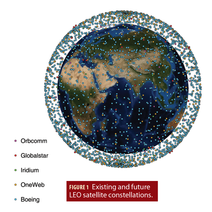
LEO satellites are particularly attractive aiding sources for an INS in GNSS-challenged environments for several reasons. First, LEO satellites are around 20 times closer to Earth compared to GNSS satellites that reside in medium Earth orbit (MEO), making LEO satellites’ received signals significantly more powerful. Second, LEO satellites orbit the Earth at much faster rates compared to GNSS satellites, making LEO satellites’ Doppler measurements attractive to exploit. Third, the recent announcements by OneWeb, Boeing, SpaceX (Starlink), Samsung, Kepler, Telesat, and LeoSat to provide broadband internet to the world via satellites will collectively bring thousands of new LEO satellites into operation, making their signals abundant and diverse in frequency and direction. Figure 1 depicts a subset of existing and future LEO satellite constellations.
Table 1 summarizes the number of satellites and the transmission band of each constellation.
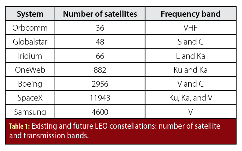
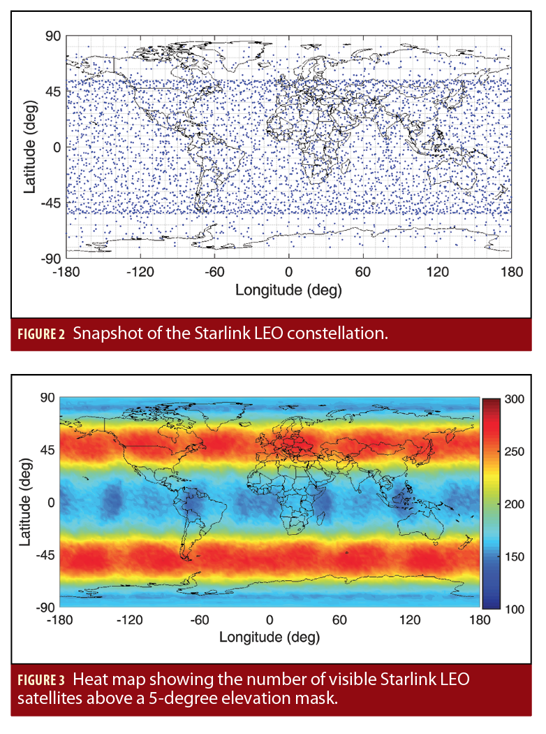
Figure 2 depicts a snapshot of the upcoming Starlink constellation, while Figure 3 is a heat map of the number of visible Starlink LEO satellites above an elevation mask of 5 degrees.
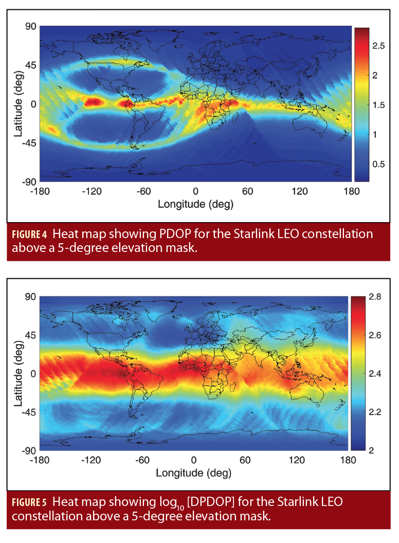
Figure 5 is a heat map showing the position dilution of precision (PDOP) for the Starlink constellation, while Figure 5 is a heat map showing the logarithm of the Doppler position dilution of precision (DPDOP).
Figure 2 through Figure 5 together with Table 1 demonstrate the potential of using LEO satellite signals for PNT and imply that the commercial space industry is inadvertently creating new PNT sources, which could be utilized by future vehicles to make the vehicle’s PNT system more resilient and accurate. For example, a Tesla connected to Starlink satellites could dually provide a passenger with internet access, as designed, while also enabling the vehicle to navigate in GNSS-challenged environments.
There are several challenges that need to be addressed to exploit LEO satellites for navigation. First, their positions and velocities must be known. The position and velocity of any satellite may be parameterized by its Keplerian elements. These elements are tracked, updated once daily, and made publicly available by the North American Aerospace Defense Command (NORAD) [see North American Aerospace Defense Command, Additional Resources]. However, these elements are dynamic and will deviate from their nominally available values due to several sources of perturbing forces, which include non-uniform Earth gravitational field, atmospheric drag, solar radiation pressure, third-body gravitational forces (e.g., gravity of the Moon and Sun), and general relativity (Vetter, Additional Resources). These deviations can cause errors in a propagated satellite orbit as high as 3 kilometers if not accounted for with corrections. Second, LEO satellites are not necessarily equipped with an atomic clock, nor are they precisely synchronized. Subsequently, their clock error must be known alongside their position and velocities. In contrast to GNSS, where corrections to the orbital elements and clock errors are periodically transmitted to the receiver in the navigation message, such orbital element and clock corrections may not be available for LEO satellites; in which case they must be estimated along with the receiver’s states. Third, ionospheric delay rates become significant for LEO satellites, particularly the ones transmitting in the very high frequency (VHF) band.
This article presents a simultaneous tracking and navigation (STAN) framework that addresses the aforementioned challenges (for more, see 2 papers from Morales, et alia). This framework tracks the states of LEO satellites while simultaneously using pseudorange and Doppler measurements extracted from their signals to aid the vehicle’s INS. The performance of the STAN framework is demonstrated in realistic simulation environments and experimentally on a ground vehicle and on an unmanned aerial vehicle (UAV), showing the potential of achieving meter-level-accurate navigation.
Pseudorange, Doppler Measurement Model
This section describes the LEO satellite receiver pseudorange and Doppler measurement model and discusses the sources of error in LEO-based positioning: (i) satellite position and velocity errors, (ii) satellite and receiver clock errors, and (iii) ionospheric and tropospheric delay rate errors.
A. PSEUDORANGE AND DOPPLER MEASUREMENT MODEL
The LEO receiver extracts pseudorange and Doppler frequency measurements from LEO satellite signals. A pseudorange rate measurement can be obtained from
where is the speed of light and is the carrier frequency. The pseudorange from the m-th LEO satellite at time-step , which represents discrete-time at for an initial time and sampling time T, is modeled as
where , represents discrete-time at with being the true time-of-flight of the signal from the m-th LEO satellite; and are the LEO receiver’s and m-th LEO satellite’s 3-D position vectors, respectively; and are the LEO receiver and the m-th LEO satellite transmitter clock biases, respectively; and are the ionospheric and tropospheric delays, respectively, affecting the m-th LEO satellite’s signal; and is the pseudorange measurement noise, which is modeled as a white Gaussian random sequence with variance . The pseudorange rate measurement from the m-th LEO satellite is given by
where and are the LEO receiver’s and m-th LEO satellite’s 3-D velocity vectors, respectively; and are the LEO receiver and the m-th LEO satellite transmitter clock drifts, respectively; and are the drifts of the ionospheric and tropospheric delays, respectively, affecting the m-th LEO satellite’s signal; and is the pseudorange rate measurement noise, which is modeled as a white Gaussian random sequence with variance.
B. POSITION AND VELOCITY ERRORS
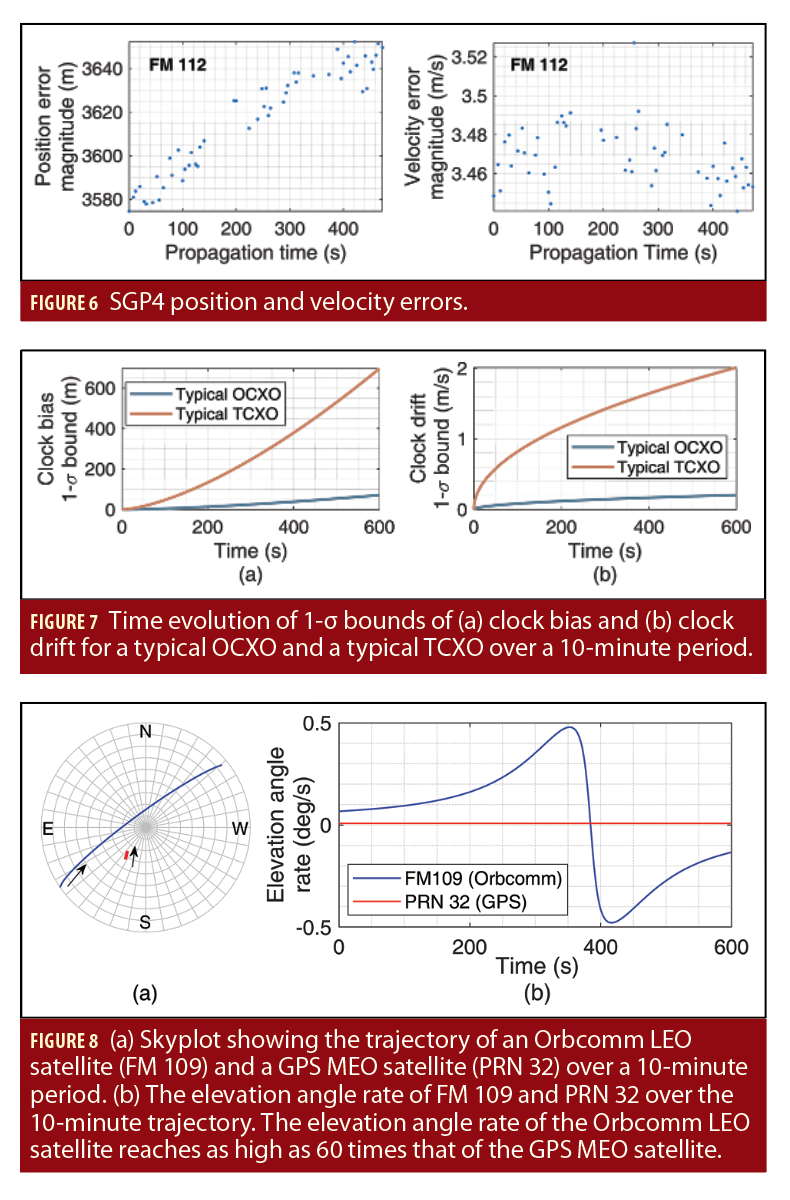
One source of error that should be considered when navigating with LEO satellite signals arises due to imperfect knowledge of the LEO satellites’ position and velocity. This is due to time-varying Keplerian elements caused by several perturbing accelerations acting on the satellite. Mean Keplerian elements and perturbing acceleration parameters are contained in publicly available two-line element (TLE) file sets. The information in these files may be used to initialize a simplified general perturbations (SGP) model, which is specifically designed to propagate a LEO satellite’s orbit. SGP propagators (e.g., SGP4) are optimized for speed by replacing complicated perturbing acceleration models that require numerical integrations with analytical expressions to propagate a satellite position from an epoch time to a specified future time. The tradeoff is in satellite position accuracy: the SGP4 propagator has around 3 km in position error at epoch and the propagated orbit will continue to deviate from its true one until the TLE files are updated the following day. Figure 6 shows the accumulated position and velocity error for an Orbcomm LEO satellite (FM 112).
C. CLOCK ERRORS
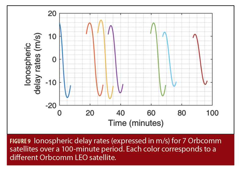
In contrast to GNSS, LEO satellite clocks are not tightly synchronized and the clock errors (bias and drift) are unknown to the receiver. Moreover, LEO satellites are not necessarily equipped with high-quality atomic clocks. From what is known about the existing LEO constellations, LEO satellites are equipped with oven-controlled crystal oscillators (OCXOs). Practically, the navigating receiver will be equipped with a lower quality oscillator, e.g., a temperature-compensated crystal oscillator (TCXO). To visualize the magnitude of the clock errors in the satellite and receiver clocks, Figure 7 depicts the time evolution of the bound of the clock bias and drift of a typical OCXO and a typical TCXO, obtained from the so-called two-state clock model (Brown and Hwang, Additional Resources). It can be seen from Figure 7 that the satellite and receiver clock bias and drift may become very significant; therefore, they must be accounted for appropriately.
D. IONOSPHERIC DELAY ERRORS
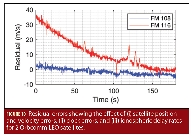
Most broadband LEO constellations reside above the ionosphere, which in turn will induce delays into their signals. Although LEO satellite signals propagate through the troposphere, its effect is less significant compared to ionospheric propagation. The magnitude of the ionospheric delay rate is (i) inversely proportional to the square of the carrier frequency and (ii) proportional to the rate of change of the obliquity factor, which is determined by the time evolution of the satellite’s elevation angle. Note that the ionospheric delay rates also depend on the rate of change of the total electron content (TEC) at zenith, denoted by TECV. However, TECV varies much slower than the satellite’s elevation angle; hence, its effect may be ignored. The effect of ionospheric propagation is significant on LEO satellite signals since (i) the high speed of LEO satellites translates into very fast changing elevation angles, as shown in Figure 8 and (ii) some of the existing LEO satellites transmit in the VHF band where the signals experience very large delay rates. The aforementioned factors result in large ionospheric delay rates, as shown in Figure 9 for 7 Orbcomm satellites over a 100-minute period.
In order to visualize the effect of (i) the satellite position and velocity errors, (ii) the clock drift error, and (iii) the ionospheric delay rates, the residual error between the measured pseudorange rate and the pseudorange rate estimated from the satellite position and velocity obtained from TLE files and SGP4 are plotted in Figure 10 for 2 Orbcomm satellites (FM 108 and FM 116).
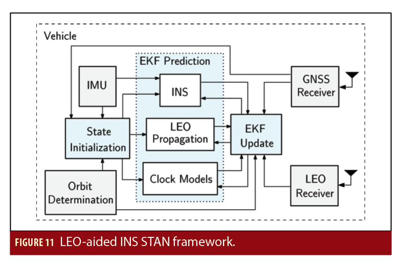
STAN Framework
To exploit LEO satellite signals for navigation, their states must be known. Unlike GNSS satellites that periodically transmit accurate information about their positions and clock errors, such information about LEO satellites may be unavailable. The STAN framework addresses this by extracting pseudorange and Doppler measurements from LEO satellite to aid the vehicle’s INS, while simultaneously tracking the LEO satellites. The STAN framework employs an extended Kalman filter (EKF) to simultaneously estimate the vehicle’s states with the LEO satellites’ states. Figure 11 depicts the STAN framework.
Simulation Results
This section presents simulation results obtained with a realistic simulation environment demonstrating UAVs navigating via the LEO-aided INS STAN framework without GNSS signals. The first subsection evaluates the achieved performance from current LEO constellations (Globalstar, Orbcomm, and Iridium), while the second subsection evaluates the achieved performance with an upcoming LEO constellation: Starlink.
A. UAV SIMULATION WITH THE GLOBALSTAR, ORBCOMM,
AND IRIDIUM LEO CONSTELLATIONS
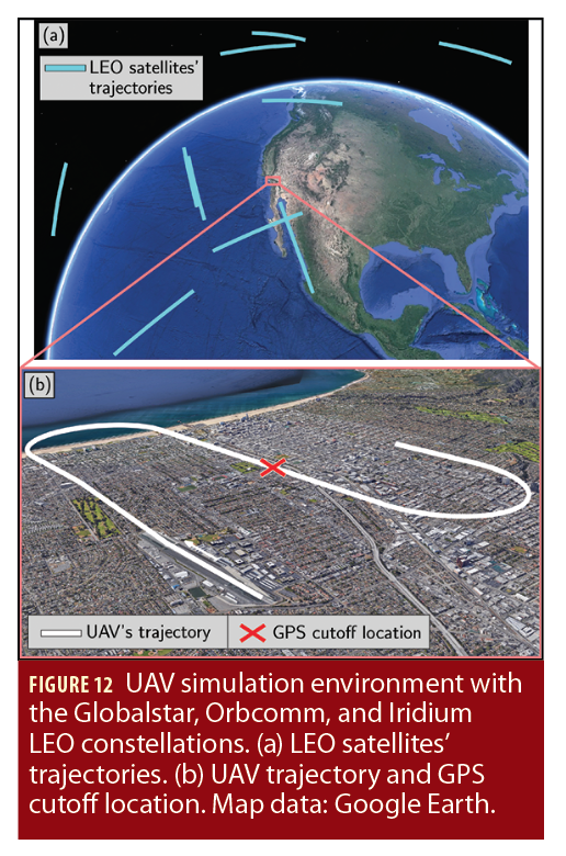
A UAV was equipped with (i) a tactical-grade IMU, (ii) GPS and LEO satellite receivers, and (iii) a pressure altimeter. The UAV navigates over Santa Monica, California, USA, for about 25 kilometers in 200 seconds, during which it had access to GPS signals only for the first 100 seconds. After lift-off, the UAV makes 4 banking turns. A total of 10 LEO satellite trajectories were simulated. The LEO satellite orbits corresponded to the Globalstar, Orbcomm, and Iridium constellations. The UAV made pseudorange and pseudorange rate measurements to all 10 LEO satellites throughout the entire trajectory. The LEO satellites’ positions and velocities were initialized using TLE files and SGP4 propagation. Figure 12 shows the trajectories of the simulated LEO satellites and the UAV along with the location at which GPS signals were cut off.
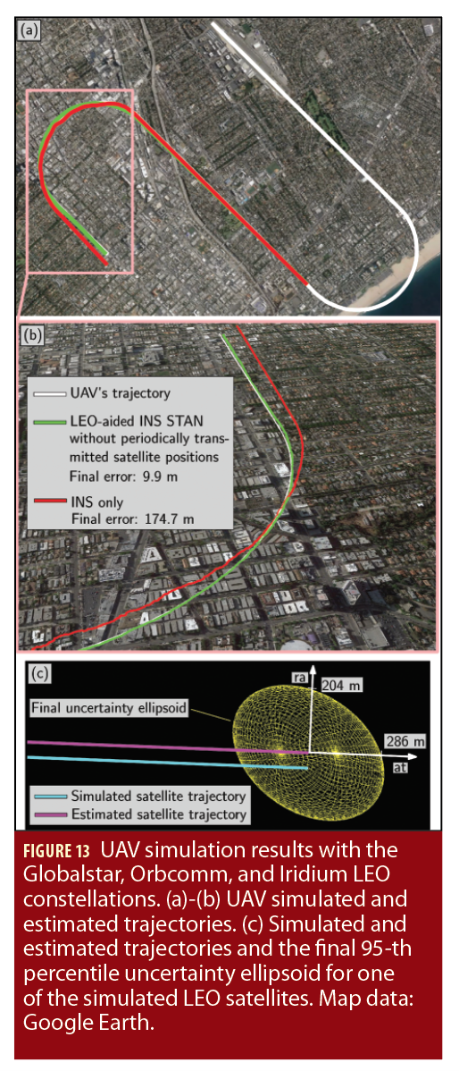
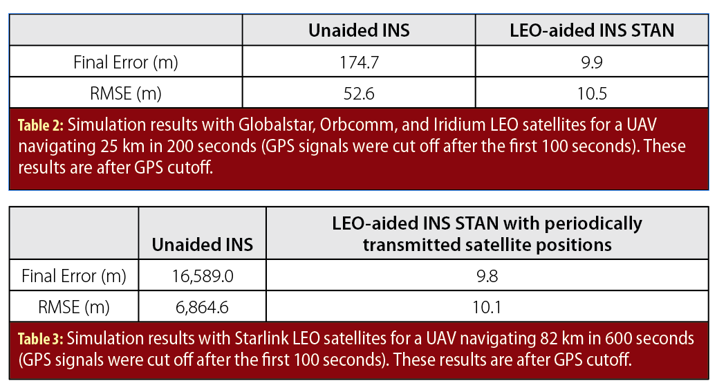
To estimate the UAV’s trajectory, 2 navigation frameworks were implemented: (i) the LEO-aided INS STAN framework and (ii) a traditional GPS-aided INS for comparative analysis. Each framework had access to GPS for only the first 100 seconds. Figure 13(a)-(b) illustrate the UAV’s true trajectory and those estimated by each of the 2 frameworks while Figure 13(c) illustrates the simulated and estimated trajectories of one of the LEO satellites, as well as the final 95-th percentile uncertainty ellipsoid (the axes denote the radial (ra) and along-track (at) directions). Table 2 summarizes the final error and position root mean squared error (RMSE) achieved by each framework after GPS cutoff.
B. UAV SIMULATION WITH THE STARLINK LEO CONSTELLATION WITH PERIODICALLY TRANSMITTED LEO SATELLITE POSITIONS
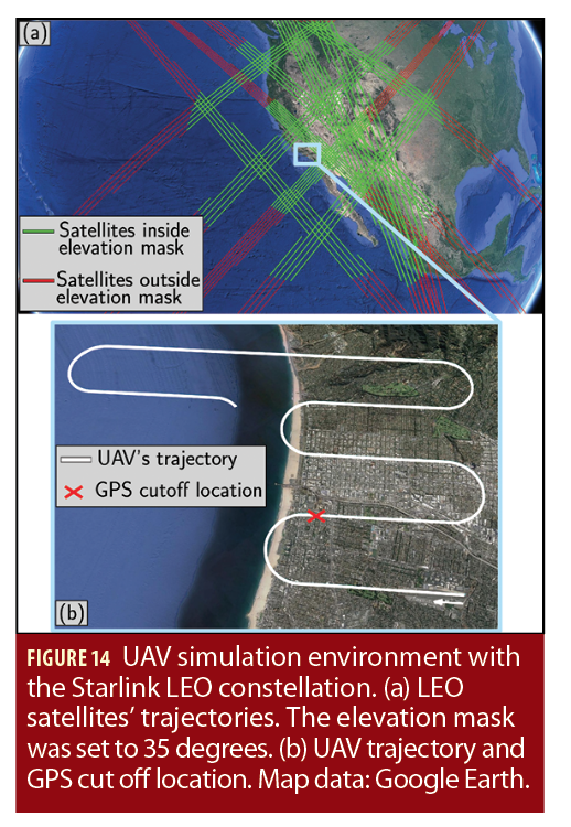
A UAV was equipped with (i) a tactical-grade IMU and (ii) GPS and LEO satellite receivers. The UAV navigates over Santa Monica, California, USA, for about 82 kilometers in 10 minutes, during which it had access to GPS signals only for the first 100 seconds. After lift-off, the UAV makes 10 banking turns. The simulated LEO satellite trajectories corresponded to the upcoming Starlink constellation. It was assumed that the LEO satellites were equipped with GPS receivers and were periodically transmitting their estimated position. There was a total of 78 LEO SVs that passed within a preset 35° elevation mask set, with an average of 27 SVs available at any point in time. The UAV made pseudorange and pseudorange rate measurements to all LEO satellites. The LEO satellites’ positions in the STAN framework were initialized using the first transmitted LEO satellite positions, which were produced by the GPS receivers onboard the LEO satellites. Figure 14 shows the trajectories of the simulated LEO satellites and the UAV along with the location at which GPS signals were cut off (Ardito et alia).
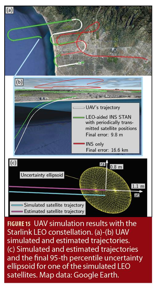
To estimate the UAV’s trajectory, 2 navigation frameworks were implemented to estimate the vehicle’s trajectory: (i) the LEO-aided INS STAN framework and (ii) a traditional GPS-aided INS for comparative analysis. Each framework had access to GPS for only the first 100 seconds. Figure 15(a)-(b) illustrate the UAV’s true trajectory and those estimated by each of the 2 frameworks while Figure 15(c) illustrates the simulated and estimated trajectories of one of the LEO satellites, as well as the final 95-th percentile uncertainty ellipsoid (the axes denote the radial (ra) and along-track (at) directions). Table 3 summarizes the final error and position RMSE achieved by each framework after GPS cutoff.
EXPERIMENTAL DEMONSTRATIONS
This section describes the existing Orbcomm LEO constellation and the LEO receiver. Then, it demonstrates the performance of the LEO-aided INS STAN framework on a ground vehicle and a UAV with real Orbcomm satellite signals.
Orbcomm System Overview
The Orbcomm system is a wide area two-way communication system that uses a constellation of LEO satellites to provide worldwide geographic coverage for sending and receiving alphanumeric packets (See Orbcomm, Additional Resources). The Orbcomm system consists of 3 main segments: (i) subscriber communicators (users), (ii) ground segment (gateways), and (iii) space segment (constellation of satellites). These segments are briefly discussed next.
(i) Subscriber Communicators (SCs): There are several types of SCs. Orbcomm’s SC for fixed data applications uses low-cost VHF electronics. The SC for mobile two-way messaging is a hand-held, standalone unit.
(ii) Ground Segment: The ground segment consists of gateway control centers (GCCs), gateway Earth stations (GESs), and the network control center (NCC). The GCC provides switching capabilities to link mobile SCs with terrestrial-based customer systems via standard communications modes. GESs link the ground segment with the space segment. GESs mainly track and monitor satellites based on orbital information from the GCC and transmit to and receive from satellites, the GCC, or the NCC. The NCC is responsible for managing the Orbcomm network elements and the gateways through telemetry monitoring, system commanding, and mission system analysis.
(iii) Space Segment: Orbcomm satellites are used to complete the link between the SCs and the switching capability at the NCC or GCC.
Orbcomm LEO Satellite Constellation
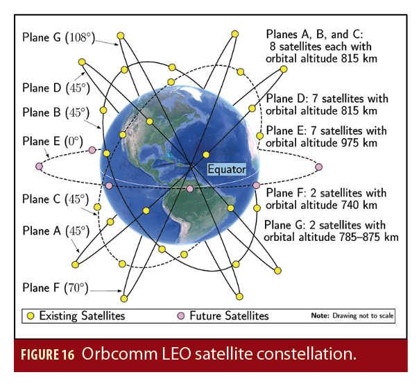
The Orbcomm constellation, at maximum capacity, has up to 47 satellites in 7 orbital planes A–G, as illustrated in Figure 16. Planes A, B, and C are inclined at 45° to the equator and each contains 8 satellites in a circular orbit at an altitude of approximately 815 kilometers. Plane D, also inclined at 45°, contains 7 satellites in a circular orbit at an altitude of 815 kilometers. Plane E is inclined at 0° and contains 7 satellites in a circular orbit at an altitude of 975 kilometers. Plane F is inclined at 70°and contains 2 satellites in a near-polar circular orbit at an altitude of 740 kilometers. Plane G is inclined at 108° and contains 2 satellites in a near-polar elliptical orbit at an altitude varying between 785 and 875 kilometers.
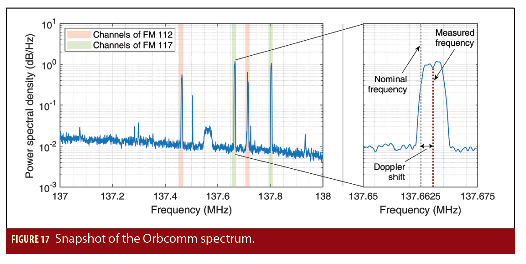
The LEO receiver draws pseudorange rate observables from Orbcomm LEO signals on the downlink channel. Satellite radio frequency (RF) downlinks to SCs and GESs are within the 137–138 MHz VHF band. The downlink channels include 12 channels for transmitting to the SCs and one gateway channel, which is reserved for transmitting to the GESs. Each satellite transmits to the SCs on one of the 12 subscriber downlink channels through a frequency-sharing scheme that provides 4-fold channel reuse. The Orbcomm satellites have a subscriber transmitter that provides a continuous 4800 bits-per-second (bps) stream of packet data using symmetric differential-quadrature phase shift keying (SD-QPSK). Each satellite also has multiple subscriber receivers that receive short bursts from the SCs at 2400 bps. Figure 17 shows a snapshot of the Orbcomm spectrum.
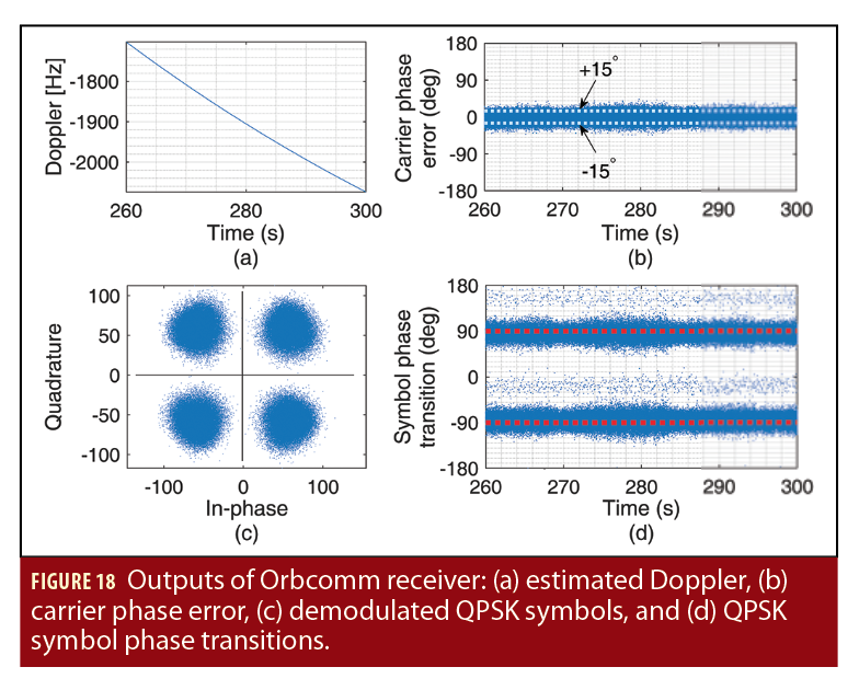
Figure 18 shows some of the internal signals of the receiver used to extract Doppler measurement from Orbcomm signals, mainly: (a) an estimate of the Doppler frequency, (b) the carrier phase tracking error, (c) the demodulated QPSK modulation, and (d) the QPSK symbol phase transitions. The Orbcomm receiver is part of the Multichannel Adaptive TRansceiver Information eXtractor (MATRIX) software-defined radio (SDR) developed by the Autonomous Systems Perception, Intelligence, and Navigation (ASPIN) Laboratory (see, http://aspin.eng.uci.edu) (Autonomous Systems Perception, Intelligence, and Navigation Laboratory, Additional Resources). The receiver performs carrier synchronization, extracts pseudorange rate observables, and decodes Orbcomm ephemeris messages.
Note that Orbcomm satellites are also equipped with a specially constructed 1-Watt ultra-high frequency (UHF) transmitter that is designed to emit a highly stable signal at 400.1 megahertz. The transmitter is coupled to a UHF antenna designed to have a peak gain of approximately 2 dB. The UHF signal is used by the Orbcomm system for SC positioning. However, experimental data shows that the UHF beacon is absent. Moreover, even if the UHF beacon were present, one would need to be a paying subscriber to benefit from positioning services. Consequently, in this work, only downlink VHF signals are used in the LEO-aided INS STAN.
Ground Vehicle Navigation
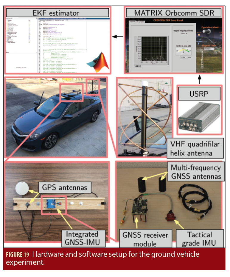
An experiment was conducted to evaluate the performance of the LEO-aided INS STAN framework on a ground vehicle traversing a long trajectory. To this end, a car was equipped with the following hardware and software setup:
• A custom-built quadrifilar helix VHF antenna
• A universal software radio peripheral (USRP) to sample Orbcomm signals. These samples were then processed by the Orbcomm receiver module of the MATRIX SDR.
• An integrated GNSS-IMU, which is equipped with a dual-antenna, multi-frequency GNSS receiver and a microelectromechanical system (MEMS) IMU. A post-processing software development kit (PP-SDK) was used to process GPS carrier phase observables collected by the GNSS-IMU and by a nearby differential GPS base station to obtain a carrier phase-based navigation solution. This integrated GNSS-IMU real-time kinematic (RTK) system was used to produce the ground truth results with which the STAN navigation framework was compared.
The experimental setup is shown in Figure 19.
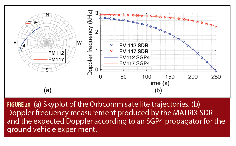
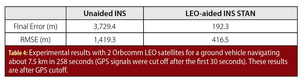
The ground vehicle was driven along U.S. Interstate 5 near Irvine, California, USA, for 7,495 meters in 258 seconds, during which 2 Orbcomm LEO satellites were available (FM 112 and FM 117). Figure 20(a) depicts a skyplot of the satellite trajectories over the course of the experiment. Figure 20(b) shows the Doppler measured by the MATRIX SDR and the estimated Doppler using satellite position and velocity obtained from TLE files and an SGP4 propagator for the 2 Orbcomm satellites.
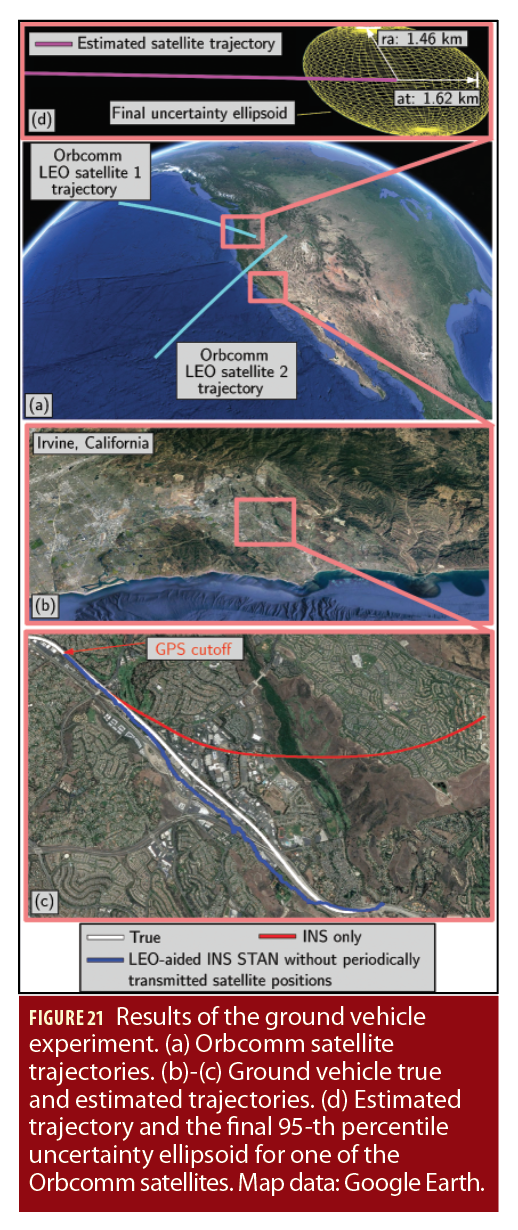
To estimate the UAV’s trajectory, 2 navigation frameworks were implemented to estimate the ground vehicle’s trajectory: (i) the LEO-aided INS STAN framework and (ii) a traditional GPS-aided INS for comparative analysis. Each framework had access to GPS for only the first 30 seconds. Figure 21(a) illustrate the trajectory the 2 Orbcomm LEO satellites traversed over the course of the experiment, Figure 21(b)-(c) illustrate the ground vehicle’s true trajectory and those estimated by each of the 2 frameworks, and Figure 21(d) illustrates the estimated trajectories of one of the Orbcomm satellites as well as the final 95-th percentile uncertainty ellipsoid (the axes denote the radial (ra) and along-track (at) directions).
Table 4 summarizes the final error and position RMSE achieved by each framework after GPS cutoff.
A. UAV NAVIGATION
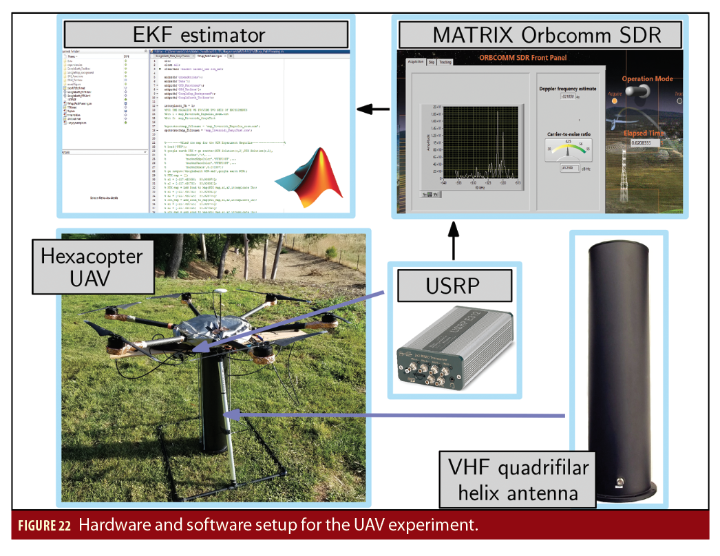
An experiment was conducted to evaluate the performance of the LEO-aided INS STAN framework on a UAV. To this end, the UAV was equipped with the following hardware and software setup:
• A high-end quadrifilar helix antenna
• A USRP to sample Orbcomm signals. These samples were then processed by the Orbcomm receiver module of the MATRIX SDR.
• A consumer-grade MEMS IMU, which is proprietary hardware of the UAV manufacturer and used in its flight controller. Log files were downloaded from the drone to parse the raw IMU data, which were subsequently fed to the INS of the STAN framework.
• A pressure altimeter, which is also proprietary hardware of the UAV manufacturer and used in its flight controller. Log files were downloaded from the drone to parse the altitude measurements, which were subsequently fed to the EKF of the STAN framework.
The ground truth trajectory was taken from the UAV’s onboard navigation system, which consists of a MEMS IMU, a multi-constellation GNSS receiver (GPS and GLONASS), a pressure altimeter, and a magnetometer. The experimental setup is shown in Figure 22.
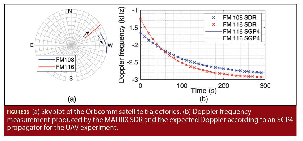
The UAV flew a commanded trajectory in Irvine, California, USA, over a 155-second period during which 2 Orbcomm LEO satellites were available (FM 108 and FM 116). Figure 23(a) depicts a skyplot of the satellite trajectories over the course of the experiment. Figure 23(b) shows the Doppler measured by the MATRIX SDR and the estimated Doppler using satellite position and velocity obtained from TLE files and an SGP4 propagator for the 2 Orbcomm satellites.
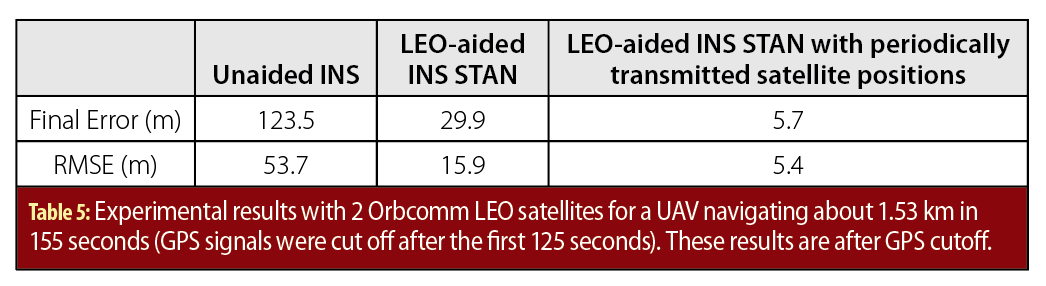
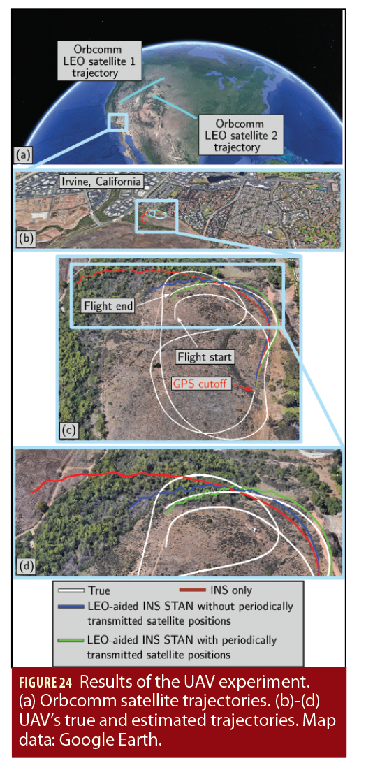
To estimate the UAV’s trajectory, 3 frameworks were implemented to estimate the UAV’s trajectory: (i) the LEO-aided INS STAN framework initialized using TLE files, (ii) the LEO-aided INS STAN framework that used the decoded periodically transmitted LEO satellite positions, which were transmitted by the Orbcomm satellites, and (iii) a traditional GPS-aided INS for comparative analysis. The estimated trajectories were compared with the trajectory extracted from the UAV’s onboard navigation system. Each framework had access to GPS for only the first 125 seconds. Figure 24(a) shows the trajectories that the 2 Orbcomm LEO satellites traversed over the course of the experiment. Figure 24(b)-(d) illustrate the UAV’s true trajectory and those estimated by each of the 3 frameworks. Table 5 summarizes the final error and position RMSE achieved by each framework after GPS cutoff.
Manufacturers
In the Ground Vehicle Navigation section, the authors’ setup included an Ettus E312 universal software radio peripheral (USRP) from Ettus Research (Austin, Texas, USA) to sample Orbcomm signals; an AsteRx-I V integrated GNSS-IMU from Septentrio (Leuven, Belgium and Torrance, California, USA); a VectorNav VN-100 microelectromechanical systems (MEMS) IMU from VectorNav Technologies (Dallas, Texas, USA); and Septentrio’s post-processing software development kit (PP-SDK) was used to process GPS carrier phase observables collected.
In the experiment conducted to evaluate the performance of the LEO-aided INS STAN framework on a UAV, a DJI Matrice 600 UAV with an A3 flight controller was used (Shenzhen, China); again, the setup included an Ettus E312 USRP from Ettus Research (Austin, Texas, USA).
Acknowledgements
This work was supported in part by the Office of Naval Research (ONR) under the Young Investigator Program (YIP) award and in part by the National Science Foundation (NSF) CAREER award under Grant 1929965. The authors would like to thank Christian Ardito, Linh Nguyen, Ali Abdallah, Mohammad Orabi, Kimia Shamaei, Mahdi Maaref, and Naji Tarabay for their help in data collection.
References
(1) Ardito, C., J. Morales, J. Khalife, A. Abdallah, and Z. Kassas, “Performance evaluation of navigation using LEO satellite signals with periodically transmitted satellite positions,” in Proceedings of ION International Technical Meeting, 2019, pp. 306-318.
(2) Autonomous Systems Perception, Intelligence, and Navigation (ASPIN) Laboratory http://aspin.eng.uci.edu
(3) Brown R., and P. Hwang, Introduction to Random Signals and Applied Kalman Filtering, 3rd ed. John Wiley & Sons, 2002.
(4) Driusso, M., C. Marshall, M. Sabathy, F. Knutti, H. Mathis, and F. Babich, “Vehicular position tracking using LTE signals,” IEEE Transactions on Vehicular Technology, vol. 66, no. 4, pp. 3376–3391, April 2017.
(5) Fang, S., J. Chen, H. Huang, and T. Lin, “Is FM a RF-based positioning solution in a metropolitan-scale environment? A probabilistic approach with radio measurements analysis,” IEEE Transactions on Broadcasting, vol. 55, no. 3, pp. 577–588, September 2009.
(6) Federal Communications Commission, “FCC boosts satellite broadband connectivity and competition in the united states,” https://www.fcc.gov/document/fcc-boosts-satellite-broadband-connectivity-competition, November 2018, accessed February 27, 2019.
(7) Hall, T., C. Counselman III, and P. Misra, “Radiolocation using AM broadcast signals: Positioning performance,” in Proceedings of ION GPS Conference, September 2002, pp. 921–932.
(8) Joerger, M., L. Gratton, B. Pervan, and C. Cohen, “Analysis of Iridium-augmented GPS for floating carrier phase positioning,” NAVIGATION, Journal of the Institute of Navigation, vol. 57, no. 2, pp. 137–160, 2010.
(9) Kassas, Z., “Collaborative opportunistic navigation,” IEEE Aerospace and Electronic Systems Magazine, vol. 28, no. 6, pp. 38–41, 2013.
(10) Kassas, Z., J. Khalife, K. Shamaei, and J. Morales, “I hear, therefore I know where I am: Compensating for GNSS limitations with cellular signals,” IEEE Signal Processing Magazine, pp. 111–124, September 2017.
(11) Kassas, Z., J. Morales, K. Shamaei, and J. Khalife, “LTE steers UAV,” GPS World Magazine, vol. 28, no. 4, pp. 18–25, April 2017.
(12) Khalife J., and Z. Kassas, “Navigation with cellular CDMA signals–part II: Performance analysis and experimental results,” IEEE Transactions on Signal Processing, vol. 66, no. 8, pp. 2204–2218, April 2018.
(13) Khalife J., and Z. Kassas, “Precise UAV navigation with cellular carrier phase measurements,” in Proceedings of IEEE/ION Position, Location, and Navigation Symposium, April 2018, pp. 978–989.
(14) Lawrence, D., H. Cobb, G. Gutt, M. O’Connor, T. Reid, T. Walter, and D. Whelan, “Navigation from LEO: Current capability and future promise,” GPS World Magazine, vol. 28, no. 7, pp. 42–48, July 2017.
(15) Maaref M., and Z. Kassas, “Ground vehicle navigation in GNSS-challenged environments using signals of opportunity and a closed-loop map-matching approach,” IEEE Transactions on Intelligent Transportation Systems, 2019, accepted.
(16) Maaref, M., J. Khalife, and Z. Kassas, “Lane-level localization and mapping in GNSS-challenged environments by fusing lidar data and cellular pseudoranges,” IEEE Transactions on Intelligent Vehicles, vol. 4, no. 1, pp. 73–89, March 2019.
(17) Merry, L., R. Faragher, and S. Schedin, “Comparison of opportunistic signals for localisation,” in Proceedings of IFAC Symposium on Intelligent Autonomous Vehicles, September 2010, pp. 109–114.
(18) Morales, J., P. Roysdon, and Z. Kassas, “Signals of opportunity aided inertial navigation,” in Proceedings of ION GNSS Conference, September 2016, pp. 1492–1501.
(19) Morales, J., J. Khalife, A. Abdallah, C. Ardito, and Z. Kassas, “Inertial navigation system aiding with Orbcomm LEO satellite Doppler measurements,” in Proceedings of ION GNSS Conference, September 2018, pp. 2718-2725.
(20) Morales, J., J. Khalife, and Z. Kassas, “Simultaneous tracking of Orbcomm LEO satellites and inertial navigation system aiding using Doppler measurements,” in Proceedings of IEEE Vehicular Technology Conference, 2019, pp. 1-6.
(21) North American Aerospace Defense Command (NORAD), “Two-line element sets,” http://celestrak.com/NO-RAD/elements/.
(22) Orbcomm, “Networks: Satellite,” https://www.orbcomm.com/en/networks/satellite, accessed September 30, 2018.
(23) Rabinowitz M., and J. Spilker, Jr., “A new positioning system using television synchronization signals,” IEEE Transactions on Broadcasting, vol. 51, no. 1, pp. 51–61, March 2005.
(24) Reid, T., A. Neish, T. Walter, and P. Enge, “Broadband LEO constellations for navigation,” NAVIGATION, Journal of the Institute of Navigation, vol. 65, no. 2, pp. 205–220, 2018.
(25) Shamaei, K., J. Khalife, and Z. Kassas, “Exploiting LTE signals for navigation: Theory to implementation,” IEEE Transactions on Wireless Communications, vol. 17, no. 4, pp. 2173–2189, April 2018.
(26) Shamaei K., and Z. Kassas, “LTE receiver design and multipath analysis for navigation in urban environments,” NAVIGATION, Journal of the Institute of Navigation, vol. 65, no. 4, pp. 655–675, December 2018.
(27) Thevenon, P., S. Damien, O. Julien, C. Macabiau, M. Bousquet, L. Ries, and S. Corazza, “Positioning using mobile TV based on the DVB-SH standard,” NAVIGATION, Journal of the Institute of Navigation, vol. 58, no. 2, pp. 71–90, 2011.
(28) Vetter, J., “Fifty years of orbit determination: Development of modern astrodynamics methods,” Johns Hopkins APL Technical Digest, vol. 27, no. 3, pp. 239–252, November 2007.
(29) Yang, C., T. Nguyen, and E. Blasch, “Mobile positioning via fusion of mixed signals of opportunity,” IEEE Aerospace and Electronic Systems Magazine, vol. 29, no. 4, pp. 34–46, April 2014.
Authors
Zaher (Zak) M. Kassas is an assistant professor in the Department of Mechanical & Aerospace Engineering and the Department of Electrical Engineering & Computer Science at the University of California, Irvine (UCI) and director of the Autonomous Systems Perception, Intelligence, and Navigation (ASPIN) Laboratory. He received a B.E. in Electrical Engineering from the Lebanese American University, an M.S. in Electrical and Computer Engineering from The Ohio State University, and an M.S.E. in Aerospace Engineering and a Ph.D. in Electrical and Computer Engineering from The University of Texas at Austin. In 2018, he received the National Science Foundation (NSF) Faculty Early Career Development Program (CAREER) award, and in 2019, he received the Office of Naval Research (ONR) Young Investigator Program (YIP) award. His research interests include cyber-physical systems, estimation theory, navigation systems, autonomous vehicles, and intelligent transportation systems.
Joshua J. Morales is a Ph.D. candidate in the Department of Electrical Engineering and Computer Science at UCI and a member of the ASPIN Laboratory. He received a B.S. in Electrical Engineering with High Honors from the University of California, Riverside. In 2016, he was accorded an Honorable Mention from the National Science Foundation (NSF). His research interests include estimation theory, navigation systems, autonomous vehicles, and intelligent transportation systems.
Joe J. Khalife is a Ph.D. candidate in the Department of Electrical Engineering and Computer Science at UCI and a member of the ASPIN Laboratory. He received a B.E. in Electrical Engineering and an M.S. in Computer Engineering from the Lebanese American University. In 2018, he received the IEEE Walter Fried Award for Best Paper at the IEEE/ION Position, Location, and Navigation Symposium (PLANS). His research interests include opportunistic navigation, autonomous vehicles, and software-defined radio.


