
Experimental and simulation results from Starlink, OneWeb, Orbcomm and Iridium LEO satellite constellations are presented, demonstrating the efficacy and tremendous promise of the proposed LEO-agnostic blind opportunistic navigation frameworks.
ZAHER (ZAK) M. KASSAS, SHARBEL KOZHAYA, JOE SAROUFIM, HAITHAM KANJ, SAMER HAYEK
AUTONOMOUS SYSTEMS PERCEPTION, INTELLIGENCE, & NAVIGATION (ASPIN) LABORATORY, THE OHIO STATE UNIVERSITY, COLUMBUS, OHIO
We are witnessing a renewed space race. From technology giants, to startups, to governments, everyone is claiming a stake in launching their own low Earth orbit (LEO) satellite constellation. These constellations promise to transform our daily lives, offering broadband connectivity anywhere on Earth, and will benefit scientific inquiry in fields such as remote sensing. However, not all such constellations are created equal. So-called mega-constellations comprising tens of thousands of satellites are on their way to becoming a reality. SpaceX’s Starlink is the clear frontrunner, with the ambitious plan to deploy nearly 12,000 LEO satellites. These constellations will be welcomed by current constellations inhabiting LEO, and collectively they could usher in a new era for positioning, navigation and timing (PNT).
This article presents current state-of-the-art PNT results with multi-constellation LEO satellite signals of opportunity (SOPs) from four LEO satellite constellations (Starlink, OneWeb, Orbcomm and Iridium) and provides an overview of a LEO-agnostic opportunistic navigation receiver, which assumes no prior knowledge of the LEO downlink signals. The receiver is capable of acquiring and tracking unknown LEO satellite signals in a blind fashion, producing Doppler navigation observables with Hz-level accuracy. A differential simultaneous tracking and navigation (DSTAN) framework is developed to deal with the poorly known nature of LEO satellite ephemerides and unknown clock errors.
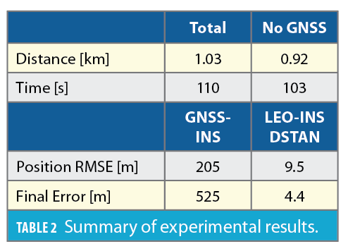
Experimental navigation results on a stationary receiver and a ground vehicle also are presented. For the stationary receiver, starting with an initial estimate about 3,600 km away, by exploiting signals from 4 Starlink, 2 OneWeb, 1 Orbcomm, and 1 Iridium, a final 2D position error of 5.1 m was achieved. The ground vehicle, equipped with an industrial-grade inertial measurement unit (IMU) and an altimeter, traversed 1.03 km in 110 seconds (GNSS signals were only available for the first 0.11 km). By exploiting signals from 4 Starlink, 1 OneWeb, 2 Orbcomm, and 1 Iridium, the 3D position root-mean squared error (RMSE) and final 3D error of DSTAN were 9.5 m and 4.4 m, respectively. These results represent the first exploitation of unknown OneWeb LEO satellite signals for PNT purposes and the first multi-constellation LEO PNT with Starlink, OneWeb, Orbcomm and Iridium satellites.
The article concludes by presenting simulation results serving as a peak to the future when Starlink and OneWeb constellations are deployed. DSTAN could achieve decimeter-level and meter-level accuracy with pseudorange and Doppler measurements, respectively, over a 23-km trajectory without GNSS.
LEO Satellites: The Benefits and Challenges
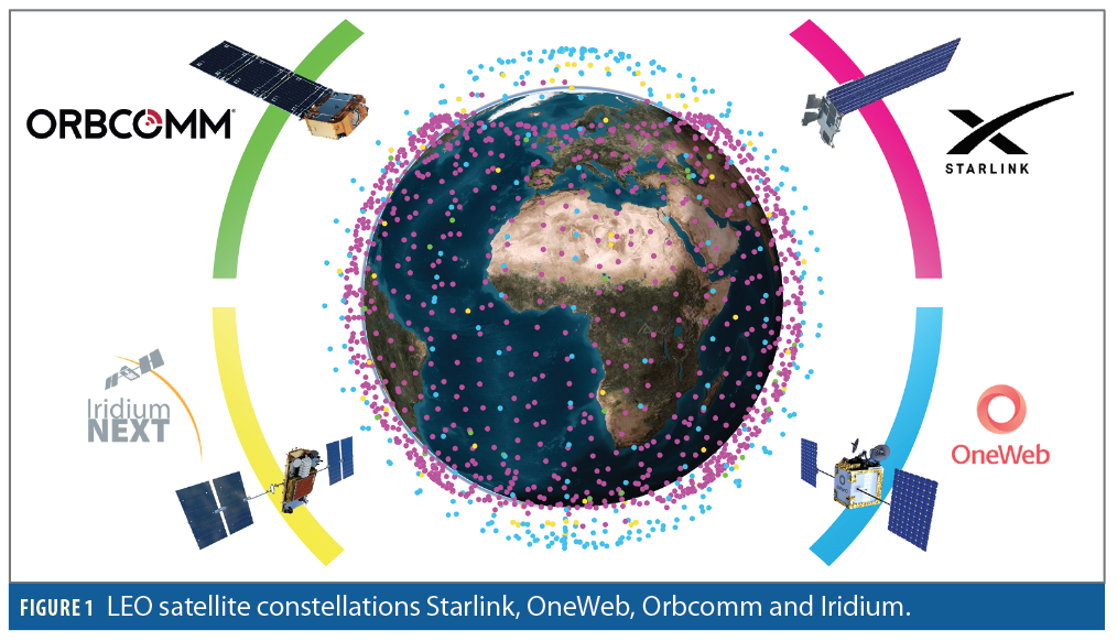
Mega-constellations of LEO satellites are being born (e.g., Starlink, OneWeb and Kuiper), joining existing LEO constellations (e.g., Orbcomm, Globalstar, Iridium, among others) [1]. These satellites will shower the Earth with a plethora of signals, diverse in frequency and direction, which could be used for PNT in a dedicated fashion or opportunistically. Figure 1 depicts the four LEO satellite constellations considered in this article.
To compensate for the limitations of GNSS, researchers have studied the exploitation of terrestrial SOPs for PNT over the last decade [2]. Exploiting SOPs did not stay Earthly, as LEO satellites have received considerable attention recently as potential SOPs. Several theoretical and experimental studies have been conducted on LEO-based PNT [3-5].
LEO satellites possess desirable attributes for PNT: (i) they are around 20 times closer to Earth compared to GNSS satellites that reside in medium Earth orbit (MEO) and could yield significantly higher carrier-to-noise ratio (CNR); (ii) they are becoming abundant as tens of thousands of broadband internet satellites are expected to be deployed into LEO; and (iii) they transmit in different frequency bands and are placed in varying orbits, making LEO satellite signals diverse in frequency and direction. However, exploiting LEO satellite signals for PNT purposes in an opportunistic fashion comes with challenges, as they are owned by private operators that typically do not disclose crucial information about the satellites’ ephemerides, clock synchronization and stability, and signal specifications.
LEO Satellite Signal Model
To exploit the unknown signals transmitted by LEO satellites, this article relies on the existence of repetitive sequences (also known as beacon) in their transmitted signals. The continuous-time baseband signal model at the receiver’s front-end after propagating in an additive white Gaussian channel (AWGN) is expressed as

where rk(t) is the received signal at tk=t0+kT0, where t0 is an initial time, k∈ is a discrete index (referred to as sub-accumulation index), T0 is the beacon length, s(t) is the beacon, and τk (t) is the apparent delay between the transmitted signal and the received signal at the receiver’s antenna (also known as the code phase). The apparent delay is the composition of multiple effects: (i) the time-of-flight along the line-of-sight between the transmitter and receiver, (ii) combined effect of the transmitter’s and receiver’s clock biases, (iii) ionospheric and tropospheric delays, and (iv) other unmodeled errors. Moreover, θk(t) is the carrier phase, which is related to the code phase by θk (t)=-2πfc τk (t), where fc is the carrier frequency of the transmitted signal. Finally, nk (t) is the sequence of the lumped channel noise and random user data. It is important to note the channel between the LEO satellite and the opportunistic receiver is highly dynamic, thus, high Doppler shift and rate will be observed by the receiver.
Blind Doppler Tracking and Navigation Beacon Estimation
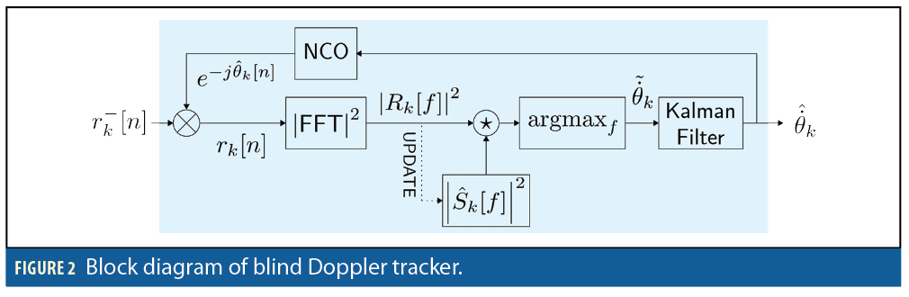
To deal with the unknown time-varying parameters modulating the received navigation beacon s(t), a blind estimation framework was proposed in [6] to track the Doppler as well as estimate the change in the code and carrier phase. The main idea behind this blind Doppler tracker is that the repetitive beacon present in the transmitted signal exhibits a prominent feature in the received signal’s spectrum. This blind estimator uses the initial received spectrum as a template and cross-correlates it with the upcoming sub-accumulations to keep track of the change in Doppler as well as to refine the estimated beacon spectrum. Working initially in a non-coherent fashion in the frequency-domain alleviates the need to deal with the complexity invoked by working in a code-carrier coherent fashion. In other words, the Doppler manifests as compression and dilation in the time-domain, as well as high drift in the code phase between consecutive sub-accumulation. These effects cannot be neglected when increasing the coherent processing interval and estimating the navigation beacon.
Figure 2 shows the block diagram of the blind Doppler estimator, where r–k[n] denotes the received signal after baseband mixing and filtering; NCO denotes a numerically-controlled oscillator; and Rk [f] and S∧k [f] are the fast Fourier transform (FFT) of rk [n] and s[n], respectively.
After successful Doppler and code phase tracking and wiping off the effect of the time-varying quantities in (1) using the proposed blind tracker, the received signal can be readily expressed as a linear model y=Hx+w. Based on this observation model, the beacon can be estimated (e.g., using least-squares). Additional details can be found in [6].
Navigation Beacon of Starlink, OneWeb Orbcomm and Iridium LEO Constellations
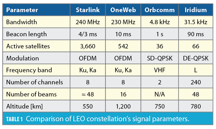
This section presents experimental results demonstrating successful beacon estimation and blind Doppler tracking for four LEO constellations, namely Starlink, OneWeb, Orbcomm and Iridium, which transmit their downlink signals according to the specifications summarized in Table 1.
Starlink LEO Constellation
The signal capture setup for Starlink used the NI-USRP x410 to collect raw IQ measurements. The sampling rate was set to 500 MHz and the carrier frequency was set to 11.325 GHz, which is roughly at the center of one of Starlink’s downlink channels in the Ku band. According to the Federal Communications Commission (FCC), the Starlink user downlink signal spectrum spans the 10.7 to 12.7 GHz frequency band. This spectrum is dissected into eight equidistant channels, each with an effective bandwidth of 240 MHz. The period of the repetitive sequence was determined by inspecting the auto-correlation function of a data snapshot that entails many frames. The repetitive sequence present in the frames of the data snapshot induces an impulse train in the auto-correlation function with spacing that was recorded to be equal to 4/3 ms. The NI-USRP x410 was set to record for a duration of 900 seconds. The proposed framework was used to acquire and track the signals present in the collected data.
OneWeb LEO Constellation
The signal capture setup for OneWeb downlink signals was the same as Starlink, with the sampling rate set to 50 MHz and the carrier frequency set to 11.075 GHz. According to the FCC, OneWeb’s user downlink signal spectrum spans the 10.7 to 12.7 GHz frequency band. This spectrum is dissected into eight equidistant channels, each with absolute bandwidth of 250 MHz. The repetitive sequence period was estimated to be 10 ms from the data snapshot auto-correlation function. The proposed blind beacon estimation framework was capable of estimating a repetitive sequence that can be used to generate Doppler and code phase observables.
Orbcomm LEO Constellation
The proposed blind beacon estimation method was applied to downlink Orbcomm LEO satellite signals. To this end, a stationary NI-USRP E312 was equipped with a commercial Orbcomm antenna to receive signals in the VHF band. The sampling rate was set to 2.4 MHz and the carrier frequency was set to 137 MHz. The duration of the recorded data was 900 seconds. Orbcomm satellites transmit at a predefined set of frequency pairs in the user downlink spectrum with an effective channel bandwidth of 4.8 kHz. After collection, the Orbcomm signal was fed to the proposed blind beacon estimator and Doppler tracker.
Iridium LEO Constellation
An NI-USRP E312 was used to capture raw signal measurements received by a commercial Iridium antenna. The sampling rate was set to 2.4 MHz, the carrier frequency was set to 1626.2708 MHz in the L band, which coincides with the ring alert (RA) channel of Iridium satellites, and the total capture duration was 600 seconds. Iridium satellites employ both time division multiple access (TDMA) and frequency division multiple access (FDMA). The Iridium spectrum consists of multiple channels, namely, the RA, paging channel, voice channel, and duplex user channels. The RA channel bandwidth is 41.667 kHz, and the beacon period is 90 ms.
The captured samples from the four LEO constellations were processed via a software-defined radio implementation (SDR) of the proposed blind Doppler tracking framework discussed in [6].
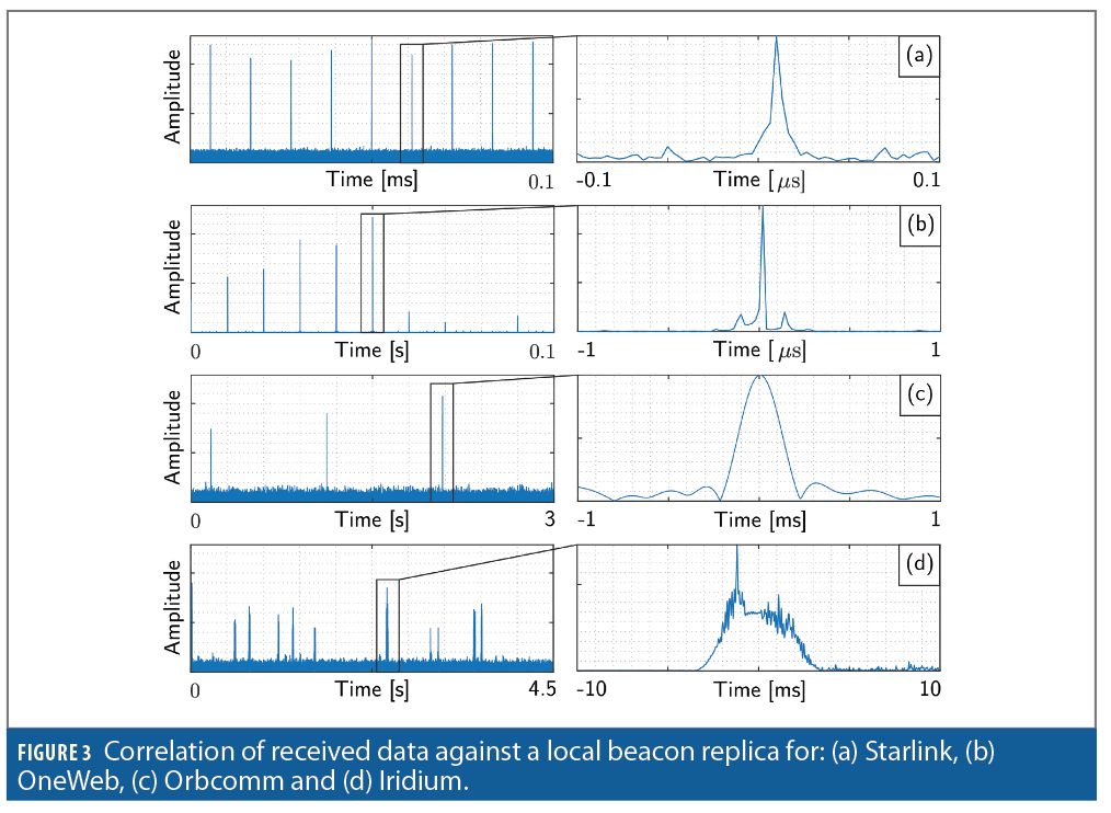
Despite each LEO constellation adopting different modulation and multiple-access strategies, the success of the proposed LEO-agnostic navigation beacon estimation framework is evident in Figure 3, which shows consistent repetitive cross-correlation peaks between the received signal and locally-generated beacon for Starlink, OneWeb, Orbcomm and Iridium.
Positioning with Multi-Constellation LEO Satellites
This section presents a multi-constellation positioning solution using signals from Starlink, OneWeb, Orbcomm and Iridium LEO constellations. The carrier phase navigation observables produced by the proposed blind beacon estimation and Doppler tracking framework are used to localize a stationary receiver.
Carrier Phase Measurement Model
Let i∈[1,L] denote the satellite’s index, where L is the total number of satellites. The carrier phase observable Φk(k) obtained by integrating the Doppler measurement to the i-th satellite at time-step k, expressed in meters, is modeled as
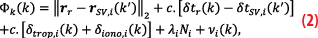
where rr is the stationary receiver’s 3D position vector in the East-North-Up (ENU) frame; rSV,i is the i-th satellite’s 3D position vector in the ENU frame; δtr and δtSV,i are the receiver’s and i-th satellite’s clock biases, respectively; δtrop,i and δiono,i are the ionospheric and tropospheric delays between the receiver and i-th satellite, respectively; c is the speed-of-light; λi is the wavelength of the i-th satellite’s signal; Ni is the carrier phase ambiguity between the receiver and i-th satellite; and νi is the measurement noise, which is modeled as a discrete-time zero-mean white sequence with variance σ2Φ,i.
In Equation 2, the time index k’ represents discrete time-step tk=t0+kT0–δtTOF,i, where δtTOF,i is the time-of-flight of the signal from the i-th satellite to the receiver. This article assumes k’≈k to simplify the formulation of nonlinear least-squares positioning. This approximation introduces an error in the LEO satellite position and clock bias. The error introduced by this approximation in the LEO satellite position is negligible compared to the position error in two-line element (TLE) files, which can be as high as a few kilometers. The receiver and LEO satellite clock error states (bias and drift) are modeled according to the standard double integrator model [4]. These terms will be lumped together and approximated as a first-order Taylor series expansion (TSE). Under these assumptions, Equation 2 can be approximated as

where aic. (δtr–δtSV,i+δtrop,i+δiono,i), and bi
c. (δ⋅tr–δ⋅tSV,i+δ⋅trop,i+δ⋅iono,i) are the zero- and first-order TSE terms, respectively, of the lumped clock errors and atmospheric delays.
Tracking Results
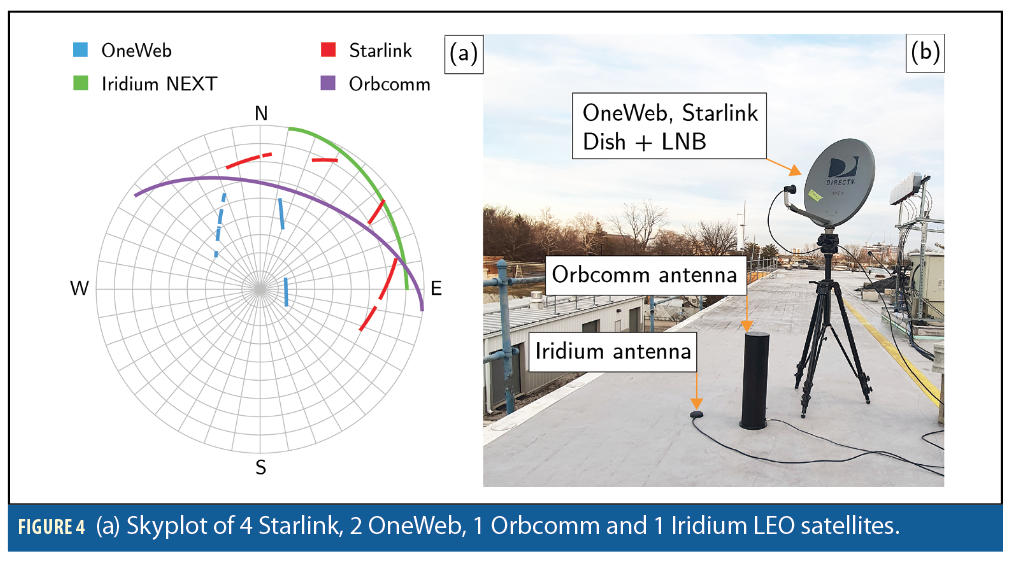
Signals from 4 Starlink, 2 OneWeb, 1 Orbcomm, and 1 Iridium LEO satellites were collected. Figure 4(a) shows the skyplot of the LEO satellites, while Figure 4(b) shows the hardware used for data collection. The hardware included: (i) a low-noise block (LNB) with conversion gain of 50 dB and noise figure of 2.5 dB connected to a Ku-band 60 cm parabolic offset dish with a gain of 30 dBi to receive Starlink and OneWeb satellite signals, (ii) a commercial Orbcomm antenna and (iii) a commercial Iridium antenna.
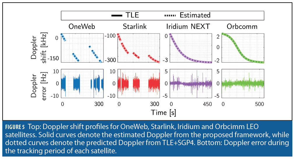
Tracking results of eight different satellites are shown in Figure 5. The top row in the figure shows the estimated (dashed) versus the TLE+SGP4-predicted (solid) Doppler shift profile for each tracked satellite. The bottom row shows the Doppler error during the tracking period. It is worth noting that even though the studied LEO constellations suffer from high Doppler (up to ~250 kHz), the blind Doppler tracking framework was able to track the Doppler with an error less than 10 Hz.
Positioning Solution
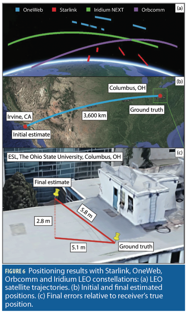
Next, a batch nonlinear least-squares estimator was employed using measurements from all LEO satellites to estimate the stationary receiver. The satellite positions were obtained from TLE files and an SGP4 orbit determination software. The TLE epoch time was adjusted for each satellite to account for ephemeris errors. This was achieved by minimizing the carrier phase residuals for each satellite [7]. The estimator’s formulation is described in [6]. The receiver’s initial position estimate was set on the roof of the Engineering parking structure at the University of California, Irvine, approximately 3,600 km away from the true position, which was on the roof of The Ohio State University’s ElectroScience Laboratory (ESL) in Columbus, Ohio. Figure 6 summarizes the positioning results. Specifically, Figure 6(a) shows the trajectories of the eight satellites from the four LEO constellations, Figure 6(b) shows the initial position estimate versus true receiver’s position, and Figure 6(c) shows the true and estimated receiver’s position. The final 3D position error was found to be 5.8 m, while the 2D position error was 5.1 m (i.e., upon considering only the east and north coordinates in the ENU frame).
Simultaneous Tracking and Navigation with Differential Measurements
Today’s vehicular navigation systems rely on a GNSS-aided inertial navigation system (INS). This GNSS/INS integration, which can be loose, tight, or deep, provides a navigation solution that benefits both the short-term accuracy of the INS and the long-term stability of GNSS [8]. In the STAN framework [9], LEO satellite signals are opportunistically exploited to produce navigation observables as an INS-aiding source, thus serving as a complement or even an alternative to GNSS signals. GNSS satellites are equipped with highly stable atomic clocks, are synchronized across the constellation network, and transmit their ephemeris data and clock errors to the user in their navigation message. In contrast, LEO satellites do not possess the aforementioned attributes because they are not designed for PNT purposes. Their on-board clocks are not necessarily of atomic standard nor as tightly synchronized. Moreover, they do not publicly transmit their ephemeris and clock error data in their proprietary signals.
To overcome these challenges, the STAN framework was proposed, in which the navigating vehicle’s states are simultaneously estimated with the states of the LEO satellites [9-12]. STAN employs a filter, e.g., an extended Kalman filter (EKF), to aid the vehicle’s INS with navigation observables extracted from LEO satellites’ signals in a tightly coupled fashion.
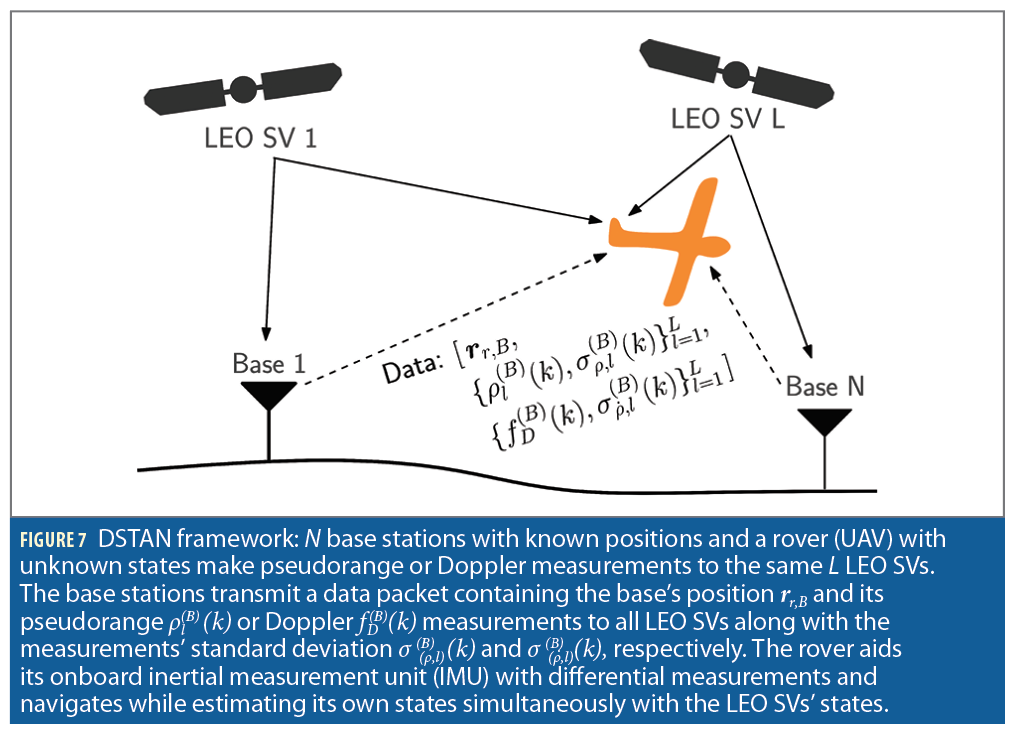
Differential positioning is a multiple-receiver PNT technique that entails computing corrections at a known base station to improve the positioning solution at an unknown rover [13-14]. To compensate for common mode errors, namely LEO space vehicle (SV) ephemerides, LEO SV clocks, and ionospheric and tropospheric delays, DSTAN was proposed to incorporate additional measurements extracted from the same LEO satellites from known base station(s), which are communicated to the navigating vehicle as shown in Figure 7 [15].
Measurement Models
This subsection describes the LEO satellite receiver pseudorange and Doppler measurement models. The differential pseudorange measurement model across the rover and the base at time-step k, which represents discrete-time at tk=t0+kT0 for an initial time t0 and sampling time T0, is defined as
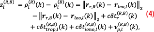
where ρl(R) and ρl(B) are the pseudorange measurements at the rover and base station, respectively, to the l-th LEO satellite; rr,R, rr,B, and rleo,l are the rover, base, and LEO satellite position vectors, respectively; c is the speed of light; δtr(R,B)is the clock bias difference between the rover and the base; and
are tropospheric and ionospheric delay differences between the rover and the base from the l-th LEO satellite, respectively; and νρ,l(R,B) is the pseudorange measurement noise difference between the rover and the base. The Doppler measurement fD extracted by the LEO receiver is related to the pseudorange rate measurement
where fC is the LEO SV carrier frequency. The differential pseudorange rate measurement model across the rover and the base is defined as
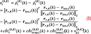
Where ρ⋅l(R) and ρ⋅l(B) are the pseudorange rate measurements at the rover and base station, respectively, to the l-th LEO satellite; r⋅r,R, r⋅r,B, and r⋅leo,l are the rover, base, and LEO satellite velocity vectors, respectively; δ⋅tr(R,B) is the clock drift difference between the rover and the base; and
are tropospheric and ionospheric delay rate differences between the rover and the base from the l-th LEO satellite, respectively; and
is the pseudorange rate measurement noise difference between the rover and base.
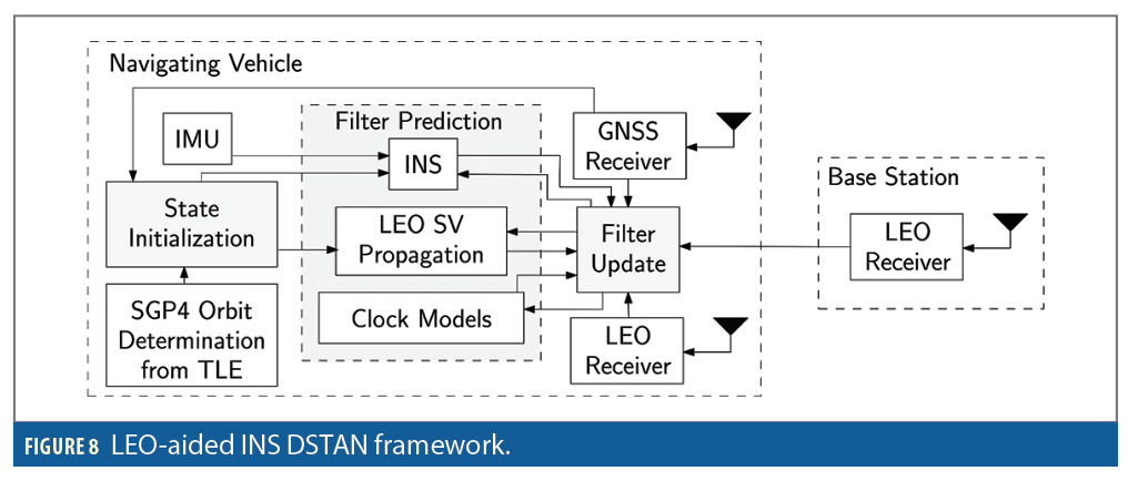
Filter Formulation
Figure 8 shows the block diagram of the DSTAN framework. The vehicle’s state vector xr consists of the vehicle’s body frame orientation with respect to the Earth-centered Earth-fixed (ECEF) reference frame ebq, the vehicle’s 3D position rr and velocity r⋅r in ECEF, and the gyroscope bgyr and accelerometer bacc biases, namely,

The clock state vector consists of the relative clock bias and drift difference between the rover and all bases, i.e.,

The l-th LEO satellite’s state vector xleo,l consists of its 3D position and velocity, expressed in the ECEF reference frame

The state vector estimated in the DSTAN EKF is formed by augmenting the vehicles’ states, clock states and each LEO satellite’s states, namely,

Ground Vehicle Navigation with LEO-aided DSTAN
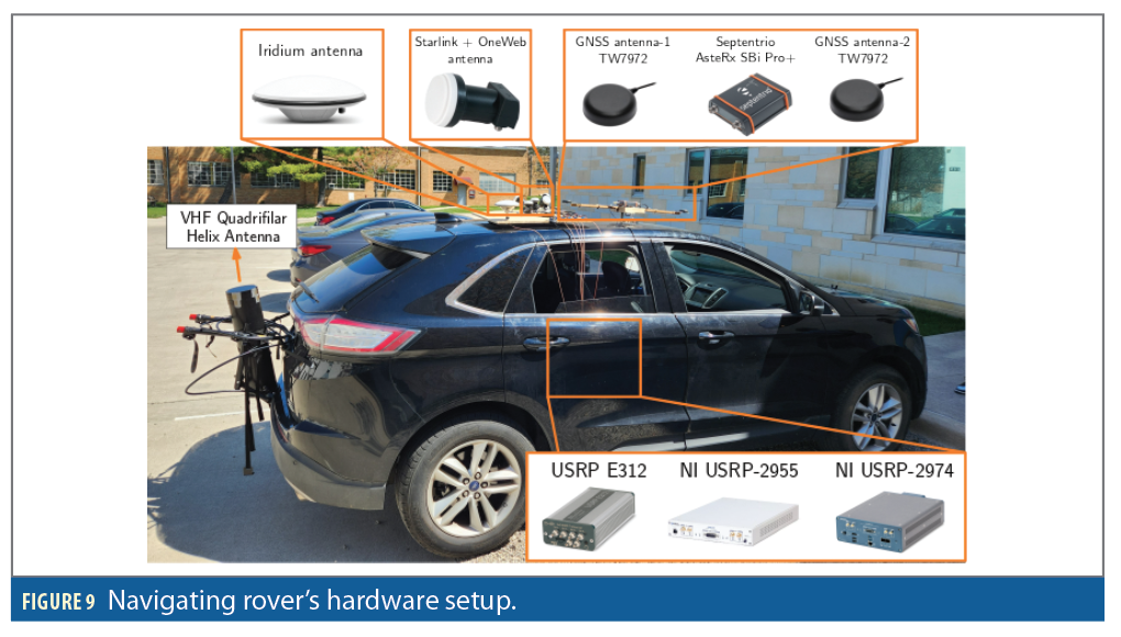
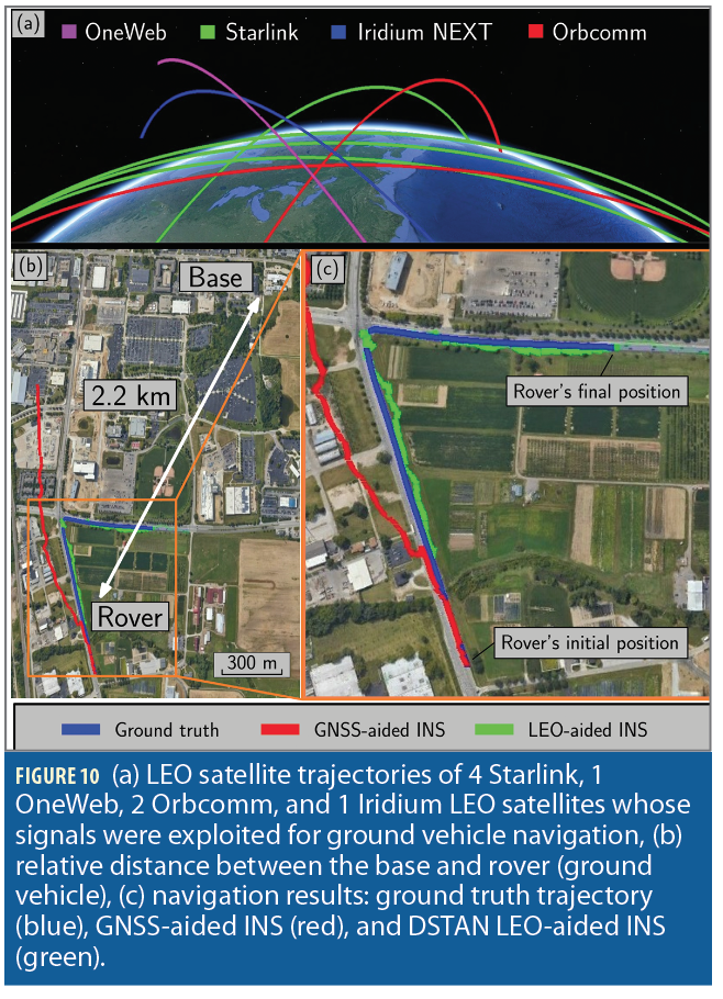
This section presents experimental results demonstrating the performance of ground vehicle navigation with 4 Starlink, 1 OneWeb, 2 Orbcomm and 1 Iridium LEO satellites via the DSTAN framework. The vehicle traversed a 1.03 km trajectory in 110 seconds, while a differential base station with known position was set up at the ElectroScience Lab at The Ohio State University campus, about 2.2 km away from the vehicle. The vehicle was equipped with a Septentrio AsteRx SBi3 Pro+ integrated GNSS-INS system with an industrial-grade IMU and an altimeter, which provided the ground truth. The vehicle was also equipped with antennas and radio frequency front ends to receive LEO signals. Figure 9shows the vehicle’s hardware setup. The base station’s setup is the same as the one shown in Figure 4.
LEO satellite signals from the four constellations were collected at the base station and the rover (ground vehicle) and were used to generate Doppler navigation observables from the receiver presented in [6]. GNSS signals were available for the first 7 seconds of the experiment but were virtually cut off for the last 103 seconds, during which the vehicle traversed a 0.92 km distance. Figure 10 shows the LEO satellites’ trajectories, relative distance between the base and rover, and the ground truth trajectory traversed by the rover versus the GNSS-INS and DSTAN navigation solutions.
Simulation Results: A Sneak Peak to the Future
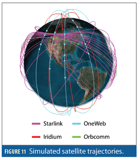
This section presents simulation results via a high fidelity simulator demonstrating the potential of DSTAN with 14 Starlink, 11 OneWeb, 3 Iridium, and 1 Orbcomm LEO satellites.
Simulation Overview
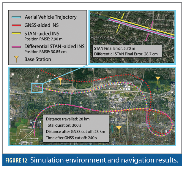
The simulation considered a fixed-wing aerial vehicle that traveled a 28 km trajectory for 300 seconds over Columbus, Ohio. The vehicle was equipped with a tactical-grade IMU, an altimeter, a GNSS receiver and a LEO receiver that produced pseudorange and Doppler measurements. The simulated environment also included three base stations equipped with LEO receivers that produced pseudorange and Doppler observables that were communicated to the aerial vehicle along with the base positions and measurement noise variances.
The mean baseline distances between the aerial vehicle along its simulated trajectory and the three base stations was 5.37, 6.01 and 4.84 km. GNSS signals were made available to the aerial vehicle for the first 60 seconds of flight time, during which GNSS measurements were fused with the INS in a loosely coupled fashion. The LEO observables were used to refine the estimates of the LEO SVs ephemerides and the rover-base(s) clock differences. During the last 240 seconds, GNSS signals were made unavailable to the vehicle, which operated in STAN mode. The altimeter measurements and LEO observables aided the on-board INS, while simultaneously estimating the LEO SVs’ ephemerides and clock differences. The LEO satellite trajectories were generated via Analytical Graphics Inc. (AGI) Systems Tool Kit (STK) using a High-Precision Orbit Propagator (HPOP). The LEO SVs, consisting of 14 Starlink, 11 OneWeb, 3 Iridium, and 1 Orbcomm satellites, were found to be visible from Columbus on January 9, 2023, at 17:00 UTC. The orbits of these SVs are shown in Figure 11.
Pseudorange and Doppler measurements were generated from the aerial vehicle and the three base stations to all visible LEO satellites. The measurement noise variances were calculated based on the predicted CNR ratio according to the log distance path loss model described in [13].
To demonstrate the benefit of the DSTAN framework, two cases were considered:
1. Standalone STAN: The aerial vehicle relied solely on the LEO observables that were extracted from its LEO receiver.
2. Differential STAN: The aerial vehicle differenced its LEO measurements from those communicated from one, two or three base stations.
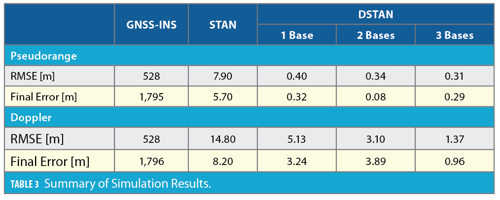
Both configurations were simulated using pseudorange or Doppler observables from the LEO receivers. Table 3 summarizes the achieved results.
Results and Discussion
The simulation environment is depicted in Figure 12, showing the base station locations and the aerial vehicle’s ground truth and estimated trajectories via the GNSS-aided INS, STAN-aided INS, and 3-base DSTAN-aided INS frameworks.
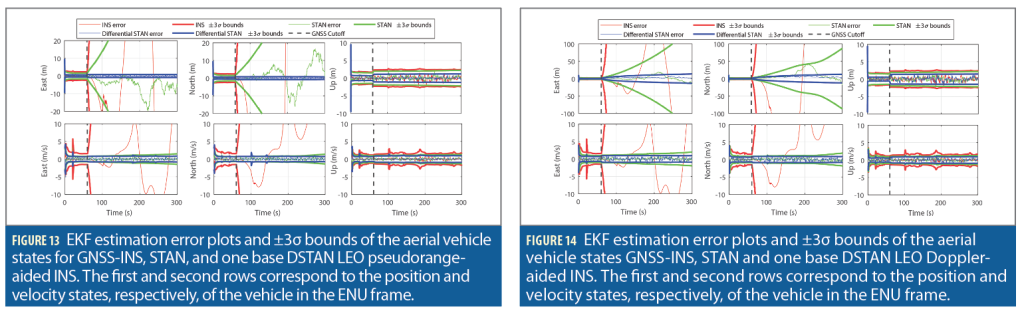
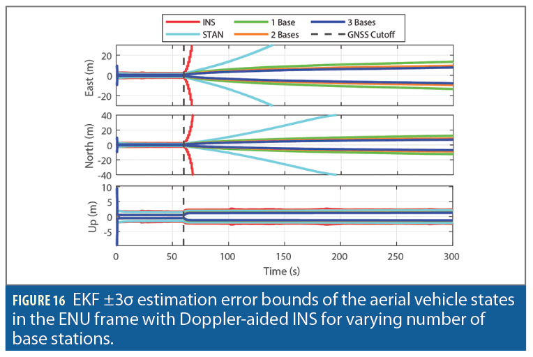
Figure 13 and Figure 14 compare the EKF errors and associated ±3σ bounds of the aerial vehicle’s position and velocity states in the East and North directions of GNSS-INS, STAN, and one base DSTAN with (i) LEO pseudorange-aided INS and (ii) LEO Doppler-aided INS, respectively. As expected, it can be seen that the GNSS-INS errors quickly diverge after GNSS cutoff. In contrast, the STAN errors diverge at a slower rate, while DSTAN significantly reduces the divergence rate. The errors of pseudorange-aiding were smaller than Doppler-aiding. Note that altimeter measurements provided non-diverging errors in the up direction in all configurations.
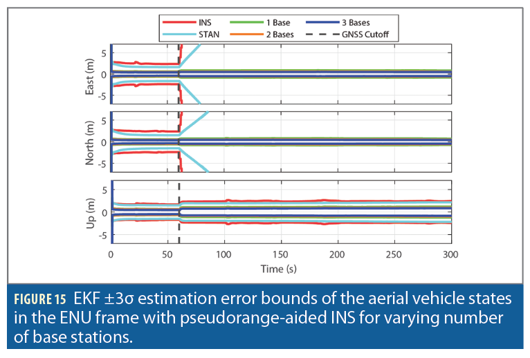
Figure 15 and Figure 16 show the effect of incorporating additional base stations on the navigation solution with pseudorange and Doppler measurements, respectively. The addition of the first base leads to significantly tighter position error uncertainty bounds, while this improvement gradually decreases with the incorporation of the second and third base stations.
This significant improvement in the navigation solution presented by the differential framework can be attributed to (i) elimination of the LEO satellite clock states from the EKF vector, (ii) additional information provided by the measurements of base stations whose positions are known, and (iii) compensation of LEO SVs’ ephemerides errors.
Acknowledgments
This work was supported in part by the Office of Naval Research (ONR) under Grants N00014-19-1-2511 and N00014-22-1-2242, in part by the Air Force Office of Scientific Research (AFOSR) under Grant FA9550-22-1-0476, in part by the National Science Foundation (NSF) under Grant 2240512, and in part by the U.S. Department of Transportation (USDOT) under Grant 69A3552047138 for the CARMEN University Transportation Center (UTC).
References
(1) N. Jardak and Q. Jault, “The potential of LEO satellite-based opportunistic navigation for high dynamic applications,” Sensors, vol. 22, no. 7, pp. 2541–2565, 2022
(2) Z. Kassas, J. Khalife, A. Abdallah, and C. Lee, “I am not afraid of the GPS jammer: resilient navigation via signals of opportunity in GPS-denied environments,” IEEE Aerospace and Electronic Systems Magazine, vol. 37, no. 7, pp. 4–19, July 2022.
(3) T. Reid, T. Walter, P. Enge, D. Lawrence, H. Cobb, G. Gutt, M. O’Conner, and D. Whelan, “Position, navigation, and timing technologies in the 21st century,” J. Morton, F. van Diggelen, J. Spilker, Jr., and B. Parkinson, Eds. Wiley-IEEE, 2021, vol. 2, ch. 43: Navigation from low Earth orbit–Part 1: concept, current capability, and future promise, pp. 1359–1379.
(4) Z. Kassas, “Position, navigation, and timing technologies in the 21st century,” J. Morton, F. van Diggelen, J. Spilker, Jr., and B. Parkinson, Eds. Wiley-IEEE, 2021, vol. 2, ch. 43: Navigation from low Earth orbit–Part 2: models, implementation, and performance, pp. 1381–1412.
(5) M. Hartnett, “Performance assessment of navigation using carrier Doppler measurements from multiple LEO constellations,” Master’s thesis, Air Force Institute of Technology, Ohio, USA, 2022.
(6) S. Kozhaya, H. Kanj, and Z. M. Kassas, “Multi-constellation blind beacon estimation, Doppler tracking, and opportunistic positioning with OneWeb, Starlink, Iridium NEXT, and Orbcomm LEO satellites,” in Proceedings of IEEE/ION Position, Location and Navigation Symposium, 2023, pp. 1184–1195.
(7) J. Khalife, M. Neinavaie, and Z. Kassas, “The first carrier phase tracking and positioning results with Starlink LEO satellite signals,” IEEE Transactions on Aerospace and Electronic Systems, vol. 56, pp. 1487–1491, 2022.
(8) D. Gebre-Egziabher, “What is the difference between ’loose’, ’tight’, ’ultra-tight’ and ‘deep’ integration strategies for INS and GNSS,” Inside GNSS Magazine, pp. 28–33, 2007.
(9) Z. Kassas, N. Khairallah, and S. Kozhaya, “Ad astra: Simultaneous tracking and navigation with megaconstellation LEO satellites,” IEEE Aerospace and Electronic Systems Magazine, 2023, accepted.
(10) Z. Kassas, J. Morales, and J. Khalife, “New-age satellite-based navigation–STAN: simultaneous tracking and navigation with LEO satellite signals,” Inside GNSS Magazine, pp. 56–65, 2019.
(11) T. Mortlock and Z. Kassas, “Performance analysis of simultaneous tracking and navigation with LEO satellites,” in Proceedings of ION GNSS Conference, pp. 2416–2429, 2020.
(12) Z. Kassas, M. Neinavaie, J. Khalife, N. Khairallah, J. Haidar-Ahmad, S. Kozhaya, and Z. Shadram, “Enter LEO on the GNSS stage: Navigation with Starlink satellites,” Inside GNSS Magazine, pp. 42–51, 2021.
(13) B. Parkinson and P. Enge, “Differential GPS,” Global Positioning System: Theory and applications., vol. 2, pp. 3–50, 1996.
(14) J. Khalife and Z. Kassas, “Performance-driven design of carrier phase differential navigation frameworks with megaconstellation LEO satellites,” IEEE Transactions on Aerospace and Electronic Systems, pp. 1–20, 2023, accepted.
(15) J. Saroufim, S. W. Hayek, and Z. M. Kassas, “Simultaneous LEO satellite tracking and differential LEO-aided IMU navigation,” in Proceedings of IEEE/ION Position, Location and Navigation Symposium, 2023, pp. 179–188.
Authors
Zaher (Zak) M. Kassas is a Professor of Electrical & Computer Engineering (ECE) at The Ohio State University and TRC Endowed Chair of Intelligent Transportation Systems (ITS). He is also Director of the Autonomous Systems Perception, Intelligence, & Navigation (ASPIN) Laboratory and Director of the U.S. Department of Transportation Center: CARMEN (Center for Automated Vehicle Research with Multimodal AssurEd Navigation), focusing on navigation resiliency and security of highly automated transportation systems. He received a B.E. in Electrical Engineering from the Lebanese American University (LAU), M.S. in ECE from The Ohio State University, and M.S.E. in Aerospace Engineering and Ph.D. in ECE from The University of Texas at Austin. He is a recipient of the National Science Foundation (NSF) CAREER award, Office of Naval Research (ONR) Young Investigator Program (YIP) award, Air Force Office of Scientific Research (AFOSR) YIP award, IEEE Walter Fried Award, Institute of Navigation (ION) Samuel Burka Award, and ION Col. Thomas Thurlow Award. He is a Fellow of the ION and a Distinguished Lecturer of the IEEE Aerospace and Electronic Systems Society. His research interests include cyber-physical systems, navigation systems and ITS.
Sharbel Kozhaya is a Ph.D. student in the Department of Electrical Engineering and Computer Science at The Ohio State University and a member of the ASPIN Laboratory. He received a B.E. in Electrical Engineering from LAU. His current research interests include cognitive sensing, opportunistic navigation, software-defined radio and low Earth orbit satellites.
Joe Saroufim is a Ph.D. student in the Department of Electrical Engineering and Computer Science at The Ohio State University and a member of the ASPIN Laboratory. He received a B.E. in Mechanical Engineering from LAU. His current research interests include situational awareness, autonomous vehicles and sensor fusion.
Haitham Kanj is a Ph.D. student in the Department of Electrical Engineering and Computer Science at The Ohio State University and a member of the ASPIN Laboratory. He received a B.E. in Electrical Engineering from LAU. His current research interests include cognitive sensing, 5G and satellite-based navigation.
Samer Watchi Hayek is a Ph.D. student in the Department of Electrical Engineering and Computer Science at The Ohio State University and a member of the ASPIN Laboratory. He received a B.E. in Mechanical Engineering from LAU. His current research interests include autonomous vehicles, sensor fusion, simultaneous localization and mapping.


