
The prototype, consisting of a single Tx-Rx communication link, was tested in indoor-to-indoor, outdoor-to-outdoor and outdoor-to-indoor communication scenarios and in both static and dynamic conditions. The outdoor-to-indoor results indicate that, with further development, the Civilian and Assets Recovery System (CARS) is a promising navigation and positioning technology.
WAHYUDIN P. SYAM, DAVID SCOTT, ALEJANDRO PÉREZ CONESA, GMV
IGNACIO RODRÍGUEZ, MELISA LÓPEZ LECHUGA, ENRIC JUAN MARTINEZ, DEPARTMENT OF ELECTRONIC SYSTEMS, AALBORG UNIVERSITY
RIGAS THEMISTOKLIS IOANNIDES, EUROPEAN SPACE AGENCY
Crisis modes, following natural or human made disasters, can happen anywhere and any time, with response teams relying heavily on the limited telecommunication and localization infrastructures available to support rescue operations. The availability of navigation and communication capabilities in these situations is vital both for distressed users and core operating rescue teams, as obtained position accuracies will determine the effectiveness of the recovery.
In these situations, a number of challenges must be overcome to provide resilient and reliable navigation. These include no access to power supplies, non-predictable environments, and the lack of operational terrestrial infrastructures. These challenges are problematic for GNSS-based or terrestrial-based positioning [1]. In addition, in difficult scenarios indoors or in urban canyons or catastrophes resulting from avalanches, floods or war, current navigation solutions, especially GNSS-based ones, are not adequate to support the required navigation functionalities.
Current Crisis Navigation Systems
There are several available communication and navigation systems available for crisis recovery and emergency scenarios. They include:
Walkie-talkies: A half-duplex communication system that uses low frequency radio signals [2] and is the basic tool for communication during an emergency.
Amateur radio: Radio communication that works within an amateur-allocated signal spectrum and is established via the ionosphere for wide range coverage that is useful in emergency situations [3].
Trunking radio: A direct communication system that relies on a computer-controlled network to manage channel assignments among different users. It has a spectral efficiency to accommodate voice and low-speed data, which is critical during a crisis. [4].
Cell on wheels: A vehicle-based mobile cell communication system where communication tower and trans receiver equipment are mounted. A deployable cell can connect to a main communication network via satellite backhaul [5], quickly establishing a 700 MHz frequency band with several kilometers of coverage for first responders.
Mobile ad-hoc-network: A communication system based on ad-hoc Wi-Fi networks with limited communication range [6]. A smartphone base mobile ad-hoc system framework that leverages available Bluetooth/Wi-Fi/Sound modules to complement hardware-based mesh networks has been presented [7].
Base station ad-hoc-network: A communication system built from disconnected base stations that can connect to cellular networks [8].
Wireless mesh networks: These consist of a self-healing, self-configuring multi-hop wireless network with different types of architectures with limited coverage [9].
UAVs and balloon-based wireless systems [10]: Drones have been used as mobile nodes to extend the coverage of existing communication systems, established using the UHF and VHF frequency bands, to provide connectivity to users located in disaster areas [11,12]. A prototype system for a balloon network using two wireless nodes in the sky to establish emergency communications through an access point and a repeater has been proposed [13]. This balloon-based system has been tested on indoor and outdoor environments and shows a coverage range of up to 2,400 m.
Device-to-device (D2D) cooperative communication: A system that allows communication between nearby mobile devices by establishing cellular or ad-hoc links [14]. The use of these systems has been demonstrated for emergency communication [15].
For outdoor navigation and positioning, GNSS has become common, with its applications widespread and accessible by most people with smartphones. GNSS is based on satellite constellations in space (commonly at medium-Earth orbit) that emit signal containing pseudorange, orbit and timing that are used to reconstruct the position of GNSS receivers on Earth [16]. GNSS has a global coverage, is in microwave frequency range and is effective for outdoor use, especially in open sky conditions. However, GNSS signals are weak and vulnerable to obstacles such as walls, roofs and tunnels. Examples of well-known global GNSS constellations are GPS [17], GLONASS [18], GALILEO [19] and BEIDOU [20].
There are indoor positioning and navigation systems based on radio frequency, optical, acoustic, magnetic signals and hybrid indoor positioning methods such as sensor fusion like LiDAR and inertial sensors. Examples of radio frequency indoor positioning systems include identification (RFID), Bluetooth low energy (BLE), Wi-Fi, Zigbee and ultra-wideband systems [21]. Optical signal-based positioning processes optical signals in infrared and visible light frequencies [22,23]. Photo-diode sensors can capture reflected lights that contain data, such as position information. Other less popular technologies leverage acoustic and magnetic signals for low-range indoor positionings [24,25].
Most of the aforementioned communication and navigation systems have drawbacks that make it difficult to use them in an emergency. For example, most only provide communication data and are not capable of providing navigation and localization (or otherwise), for either outdoor only or indoor only communication. They’re also large and heavy, aren’t portable, require an electrical power supply, require communication cell towers and other terrestrial infrastructures, have weak signal power and signal propagation capabilities (such as GNSS), have a small coverage area, need specialized equipment and trained users (such as amateur and trunking radios), can only be used indoors or outdoors, and are only for static use. In a natural disaster, a versatile, stand-alone and flexible communication system for positioning and navigation that can be used for outdoor-to-outdoor and outdoor-to-indoor communications in both static and dynamic conditions as well as in harsh environments is needed.
The first stage development of a flexible and fast-deployable Civilian and Assets Recovery System (CARS) that provides positioning capabilities in crisis situations and overcomes these challenges is presented in this article. The system accounts for these limitations, such as outdoor-to-outdoor and outdoor-to-indoor communication capability, and considers addressing further challenges, such as the need to cover wider areas, the need for lightweight devices at transmission and reception, and the need for flexibility and configurability to support operations in unpredictable hostile conditions.
Figure 1 illustrates the importance of CARS in an emergency. In Figure 1, many victims may be trapped inside wrecked buildings or underground after a natural disaster. CARS must be flexible, deploy quickly and provide good signal propagation capabilities (outdoor-to-indoor) to transmit navigation signals to receivers that are underground or inside the wrecked buildings. From Figure 1, the CARS transmission (Tx) unit should be lightweight, battery-operated, easy to mount on many types of fast-deployable moving or flying vehicles, and able to send navigation data obtained from open-sky GNSS signals or internal inertial sensors. The receiver (Rx) unit should be portable and lightweight.
The first-stage CARS prototype consists of a single Tx-Rx communication link and is built on the high-configurability and flexibility of a software defined radio (SDR) device. This system emits signals that contain ranging information and has the propagation capability advantages that low frequency radio frequency (Low_RF) signals provide. The transmitter of the Low-RF system is based on a battery-powered SDR that can be mounted onto any terrestrial moving or flying vehicle, such as cars, trucks, cell-on-wheels and drones.
Radio Signal Propagation in a Cluttered Environment
CARS must exploit good signal propagation capabilities to improve the system’s area coverage. Low frequency (sub-GHz) transmissions have lower outdoor propagation and penetration losses into buildings than higher frequency transmissions [26, 27], especially in a harsh environment [28]. This low propagation and penetration loss will increase the ability to transmit and receive signals in a cluttered environment, such as urban canyons and indoor/multi-floor transmission. In addition, with operation at narrow signal bandwidth, the low power requirement for the transmission will be obtained. An outdoor-to-indoor RF propagation in an urban-cluttered scenario is used to evaluate and study the RF propagation capability for the developed first-stage CARS protoype.
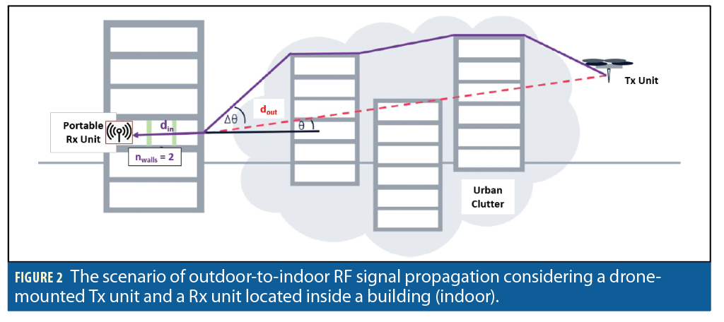
The outdoor-to-indoor RF signal propagation is presented in Figure 2. In this scenario, the Tx unit is always outdoors on a moving or flying vehicle. The Rx unit is in a building and obscured by walls and windows. The outdoor propagation loss can be modeled over the link from the Tx unit to the external facades of the building, and to the Rx unit behind walls inside the building. In Figure 2, dout is the linear distance from the Tx unit to the incident point on the building façade as specific incident angle θ. din is the linear distance from the incident point on the facade to the Rx unit passing, in this case, two walls (nwalls=2). In this work, dout is expected to be up to 2 km as the design choice of this case study. The RF signal propagation scenario shown in Figure 2 considers all conditions impacting the propagation loss: outdoor-to-outdoor, outdoor-to-indoor and indoor-to-indoor. Hence, this scenario can accuratley evaluate the proposed first-stage CARS for outdoor-to-indoor communication. In Figure 2, the urban clutter affects the true incident angle at the façade point and the height of the Tx unit affects the signal propagation trajectories. The higer the Tx unit height from the ground, the less effect the urban clutter will have on signal propagation loss.
The main propagation mechanisms considered are propagation in-between buildings [29], propagation above rooftops and multi-screen diffractions at the rooftop edges [30,31], external facade penetration loss through low-attenuating window and loss due to the grazing incident angle [32], and propagation loss due to guided indoor propagation and walls/doors/multi-floor openings [33]. The total propagation-loss (PLout-to-in) of the outdoor-to-indoor transmission is formulated as:

Where PLout is the propagation loss for outdoor-to-outdoor transmission and is a function of Tx height hTX, Rx height hRX, the linear distance from the Tx to an incident point of a building dout and transmission frequency f. LBEL is the propagation loss for outdoor-to-indoor transmission and is a function of building materials Bm, transmission frequency f and incident angle θ. PLin is the propagation loss for indoor-to-indoor transmission and is a function of the linear distance from the incident point on the building to the Rx unit din and number of openings nwalls, such as walls, doors and corridors.
Different building materials will significantly affect the propagation loss of RF signals when entering buildings. Losses for several materials are estimated at different frequencies (100-500 MHz) from published data [35,36,37]. In this article, two types of buildings are considered: traditional (constructed mainly of red bricks) and non-traditional thermal efficient (constructed mainly of thermal-soaked glasses and steel beam structures). These building types have different signal propagation attenuation because of their constructing materials, making it important to evaluate the propagation characteristic of transmissions of the proposed system for both.
Low-RF Communication System Development
SYSTEM ARCHITECTURE
The architecture of the Low-RF CARS consists of a transmitter/Tx (CREAM) unit and receiver/Rx (DREAM) unit that are based on reliable and highly configurable SDR devices. The system operates at a low frequency of 113 MHz to 500 MHz (UHF and VHF bands) and emits signals containing ranging and velocity information. The Tx unit is based on a compact SDR device that is battery-operated, can operate in stand-alone mode and can be mounted in various moving or flying vehicles, such as a UAV, cell-on-wheel, cars and trucks.
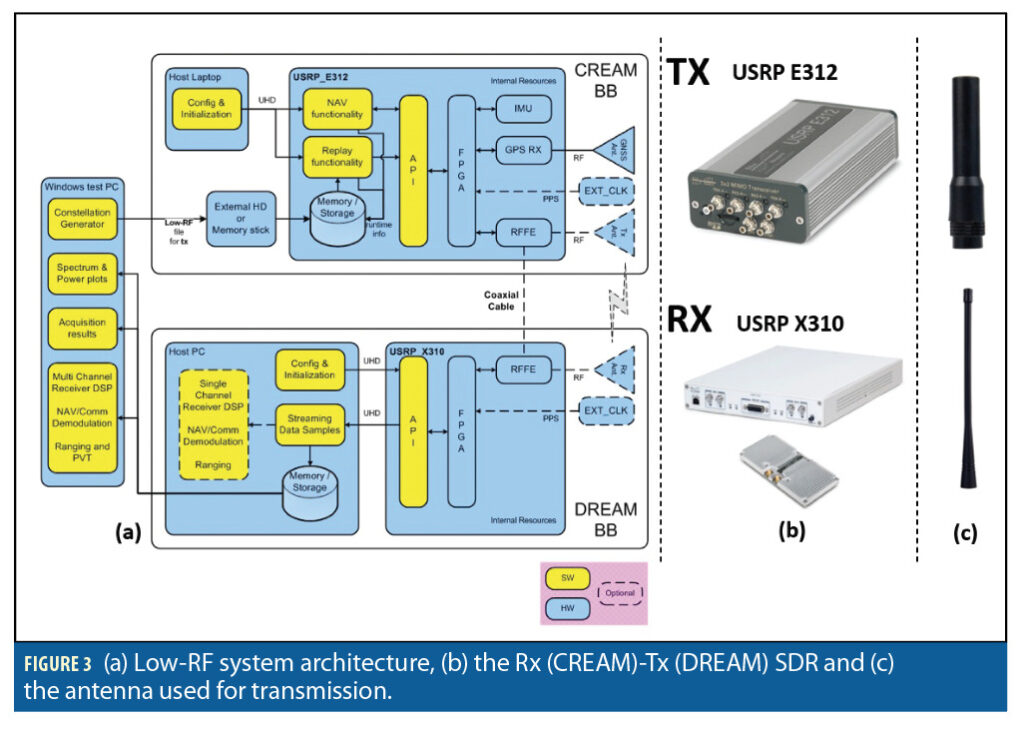
Figure 3a shows the Low-RF system architecture. The Tx unit operates using a battery and has an embedded CPU, FPGA, on-board GPS and IMU sensors. The CPU will prepare the message bit and pseudorandom (PRN) code and then modulate the signal. The prepared signal is then sent to the FPGA system for transmission. The Tx unit also can transmit a replayed signal from files. Although the Tx unit can operate in stand-alone mode, it requires a PC connection to start the operation of the Tx unit for the first time. The Rx unit is a portable SDR and needs to be connected to a host-PC to process received signals, although it could also be a laptop if device specifications are powerful enough for processing. An external clock can be connected to the Rx unit for synchronization purposes if required. All signal processing, including tracking, acquisition and demodulation, is carried out by the host-PC connected to the Rx unit. In general, the Low-RF system can use any suitable SDRs and signal designs.
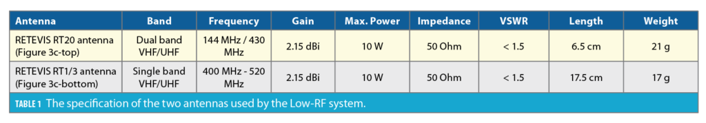
Figure 3b shows the SDR uses in the Low-RF system. The Tx unit uses Ettus USRP E312 [40] and the Rx unit uses Ettus X310 [41] devices. The E312 features a Xilinx Zynq 7020 SoC (7 Series FPGA with ARM Cortex A9 866 MHz dual-core processor) and an Analog Devices AD9361 RFIC as the RF front end. This Tx unit supports an instantaneous bandwidth up to 56 MHz and frequency range between 70 MHz and 6 GHz. The X310 is equipped with a daughterboard UBX160 as a RF front-end and features a large Xilinx Kintex-7 FPGA (XC7K410T), sampling rate up to 120 MHz and frequency between 70 MHz and 6GHz, multiple high-speed interfaces including dual 10GbE, PCIe Express and dual 1 GbE. The flexible clocking architecture allows for a configurable sampling rate and synchronization with the optional high accuracy GPS disciplined oscillators (GPSDO). RF Network on Chip (RFNoC™) FPGA development framework and Ettus UHD are used for software development. Figure 4c shows two types of antennas used for wireless transmission: RETEVIS RT20 and RETEVIS RT1/3. The two antennas are used for transmission at 113 to 500 MHz. Table 1 presents their detailed specifications.
SIGNAL DESIGN AND MESSAGE BIT STRUCTURE
The implemented signal design considers the limited processing capability of the Tx unit due to the trade-off of having low-power consumption and battery-operated capabilities. The processing power is far below a standard workstation, so the unit’s signal design should be simple and efficient. The implemented signal should follow the structure of the spread-spectrum CDMA signal and implement a GPS L1 C/A-like signal structure, transmitted at low frequency 113 MHz to 500 MHz, with a baseband bandwidth of 1.023MHz, following the PRN chip rate as 1.023 Mcps [38]. Navigation data, containing position and velocity, uses binary-phased shifted keying (BPSK) modulated in In-phase and Quadrature (I/Q).
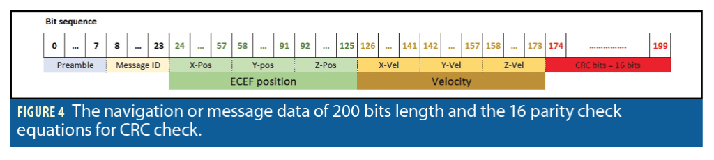
The navigation or message data contains 200 bits that are 8-bit preamble, 16-bit message id, 34-bit for each Earth-center-Earth-fixed (ECEF) X, Y, Z position, 16-bit for each ECEF X, Y, Z velocity and 16-bit cyclic-redundancy check (CRC) code as shown in Figure 4. The selected number of navigation bits is a trade-off between numbers of information to contain and the unit’s hardware limitation. These bit structures use the ECEF coordinate reference system for easy translation to any other coordinate system, have a high-resolution positioning and use message ID for message tracking and verification and Tx-Rx synchronization. The position granularity (resolution) of the navigation bit is computed as follows:
Because the position (in meters) is 24 bits to represent the integer part of the position and 10 bits to represent the decimal point of the position, the smallest value the position bit can represent is when all the bits are zero, except the least significant bit (the 34th bit), is 1. Hence, when only the least significant bit is 1, the bit will represent 1/210, that is the position granularity is approximately 0.000976 m = 0.976 mm.
NAVIGATION MESSAGE PREPARATION AND MODULATION
It is important to note that unlike receiving, where the sampling frequency should not be a multiple integer of the data rate (at a specific input frequency), the sampling frequency for transmitting should be an integer multiple of the data rate [39]. For transmitting the navigation signals, it’s necessary to up-sample the 1.023 Mcps signals to be at least 2 Mcps and the integer multiple of the sampling rate of transmissions. The signal should be up-sampled at least to 2 Mcps before being sent to digital-to-analog (DAC) processing of the Tx unit. To up-sample the signal, the PRN code is processed per one period of 1 ms. The PRN used has 1,023 samples per 1 ms. From these 1,023 samples, an up-sampling process is applied. The up-sampling process increases the number of samples or chips of the one-period PRN from 1,023 samples per 1 ms (equal to 1.023 million samples per 1 s, that is non-integer number per million) to 2,000 chips per 1 ms. By doing this up-sampling, the number of samples of the PRN becomes 2 million samples per 1 s period (integer number per million). Because the up-sampled PRN chips are not exactly 2× (that is 2,000 samples per 1 ms) of the base PRN chips (1,023 samples per 1 ms), there are chips that are multiplied by either 1× or 2×.
For the up-sampled PRN with 2,000 samples per 1 ms, two sets of bit strings are prepared, one with modulo sum 2 with 0 bit (for 0 bit navigation data) and another with modulo sum 2 with 1 bit (for 1 bit navigation data). Because the navigation data has 200 bps, the period of each bit is 5 ms. Hence, the whole navigation message is prepared for every 5 ms. If the navigation data bit is 0, then the set of bit strings that has been modulo summed 2 with 0 bit are used. Finally, all samples of navigation data for 1 s period (2 million samples) are BPSK modulated by changing the 0 bit value into 1 and 1 bit value into -1. From the 2 Mcps of the up-sample signals, these signals are then sent to the TX unit’s DAC at a sampling rate of >2×2M = 4 Mcps. In our case, the Tx sampling rate is set to be 6 Mcps (MHz). This 6 Mcps sampling rate is chosen by experiments. The experiments perform transmission-receiving tests with various different up-sampling rates and transmission sampling rates to find the maximum values the Tx unit can process.
RECEIVER SENSITIVITY
This is estimated experimentally in laboratory conditions. The sensitivity test is performed by reducing the signal power emitted by the Tx unit until the signal can no longer be acquired by the Rx unit. The transmission between the Tx and Rx unit uses a cable connection to avoid any external disturbance. When received signals cannot be acquired, the signals cannot be tracked and subsequently cannot be demodulated. The sensitivity analysis starts by transmitting Tx unit signals at minimum power, which in this case is -43.7 dBm. This power level accounts for the signal generated by the Tx unit plus any attenuation caused by the cable connection. Attenuation is progressively added at the receiver’s input until the signal processing can’t acquire the signals received by the Rx unit. Based on these tests, the Low-RF system sensitivity is between -115 dBm and -120 dBm at 10 MHz bandwidth. It is important to note these sensitivity values are the best possible sensitivity, as attenuation from channel impairments is minimal because of the cable connection. The sensitivity is expected to be lower than the sensitivity obtained from the lab test in real-world scenarios, as more factors such as channel impairments, phase coupling and other signal propagation losses add to the attenuation.
Low-RF Wireless Transmission Experiments in Different Scenarios
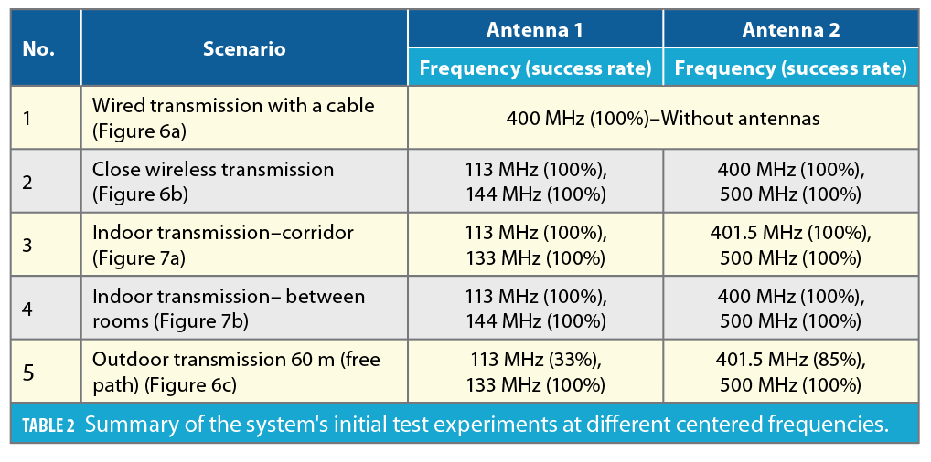
This section presents the results of wireless transmission tests performed both in laboratory, indoor, outdoor (system initial test) and real-world scenarios. To be classified as a successful transmission, the demodulated data at the Rx unit must be correct or match the data sent by the Tx unit. This main criterion is quantified as the success rate, that is the number of correct demodulated data at the Rx unit per total number of transmitted data by the Tx unit. The X,Y,Z positions and velocities in the ECEF coordinate system are obtained from the GPS sensor in the Tx unit and then fixed for the transmission tests. In all experiments, the sampling rate at the Rx unit is 10 MHz. Before real-world scenario tests, system initial tests are performed to verify the end-to-end signal processing chain and to select the best frequency for real-world scenario experiments.
SYSTEM INITIAL TEST EXPERIMENTS:
Controlled transmission with physical channel and closed wireless transmission
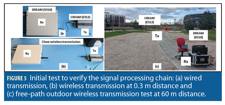
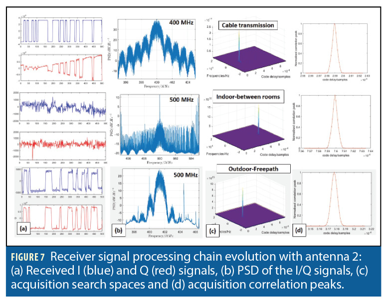
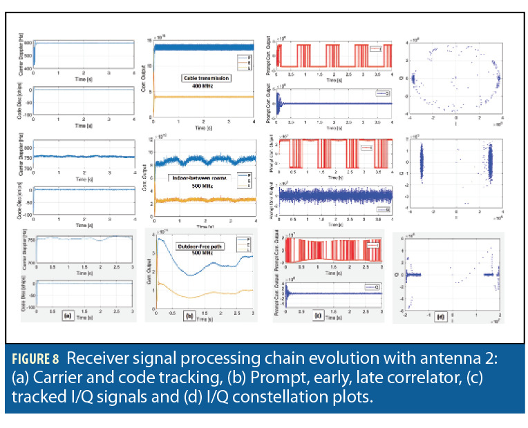
This test validates the signal modulation and demodulation and the antenna characteristics. The activities test the whole end-to-end signal processing chain from navigation message preparation and modulation until the signal receiving, acquisition, tracking and demodulation processes. Figures 5a and Figure 5b show the wired-transmission setup and the wireless transmission at a close line-of-sight of 0.3 m distance. The signal received from the wired transmission at 400 MHz contains minimal noise. The baseband signals have higher power than noise as well as a strong correlation peak (Figure 7-top). The signal tracking processes are very stable (Figure 8-top). Note that, although both the Tx and Rx are static, there is a Doppler frequency up to 400 Hz due to TCXO clock noise, that is commonly 1-2 ppm, at the Rx unit [38]. Similar to the wired transmission, the close-distance wireless transmission (at 113, 144, 400 and 500 MHz) has low noise, except for some fluctuations during signal tracking processes. A success rate of 100% is obtained from the wired and close-distance wireless transmissions (Table 2).
Static indoor-to-indoor transmission
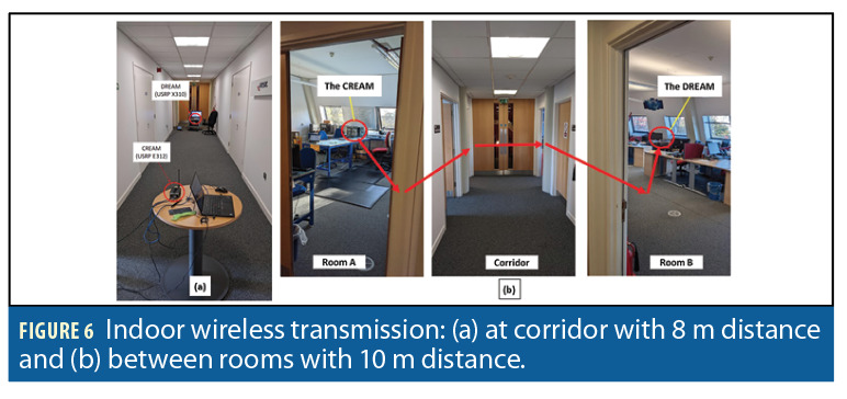
Figure 6a and 6b present indoor-corridor experiments performed at 8 m (corridor width = 2 m) and indoor-between-rooms at 10 m, between the Tx-Rx respectively. These experiments include channel impairments such as multipath and blockade effects. The transmissions consider different setup combinations for antenna 1 and 2 at 113, 133, 144, 400 and 500 MHz. Results from these experiments show a 100% transmission success rate as presented in Table 2. In some cases, the channel impairments add significant noise to the transmitted signals, especially in the indoor-between-room transmissions, where the baseband signals are buried under the noise (Figure 7-middle). Also, for tracking processes, more fluctuations on the carrier Doppler tracking are observed for indoor-between-rooms as multipath and reflection effects are stronger than the indoor-corridor scenario (Figure 8-middle). In these tests, the Doppler is about 500 to 750 Hz.
Static outdoor-to-outdoor transmission
Figure 5c shows the outdoor-free path experiments with both antennas at 113, 133, 401.5 and 500 MHz. The distance between the Tx-Rx is set to be approximately 60 m. Transmission at 113 MHz only shows a 33% success rate so it is concluded that this frequency is not effective for real-word testing. This is because 113 MHz is well outside the main radiation band of the setup antennas, which limits the efficiency of the system at this frequency. Other frequencies show a 100% success rate, except 401.5 MHz, which shows a 85% success rate. From Figure 7-bottom, it can be observed that this free-path transmission has low noise power compared to the baseband signal power (the rectangular waveforms are still observable). There are small fluctuations of the carrier tracking, shown in Figure 8-bottom, which may be caused by power loss variation.
All the correlation peaks of the signal acquisition, for 1 ms correlation length, show obvious triangle shapes indicating the signal correlation can effectively acquire the PRN code from the received signal. The selected 1 ms of correlation length is to speed up computation process and avoid data bit transition during correlations. We decided to bring 133 MHz (with antenna 1), 401.5 MHz (with antenna 2), and 500 MHz (with antenna 2) to the real-world experiments.
Real-world scenario experiments
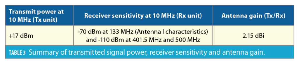
Low-RF real-world experimentations were performed at the Harwell Science and Innovation Campus (UK), which is a suburban area with a low density of two to three story buildings, single-lane roads, and is densely vegetated. Two types of buildings were considered for outdoor-to-indoor transmission: traditional (constructed of red bricks and 40 cm concrete walls) and thermal efficient (constructed of thermally soaked glasses and a steel-beam with 36 cm thickness). Table 3 shows the setup parameters of the experiments for the Tx and Rx units, which are transmitted signal power, antenna gain and effective receiver sensitivity.
Before the real-word experiments, calibrations were performed to estimate the effective signal penetration loss for the two buildings. A series of received power measurements by the Rx unit at different indoor positions were performed for calibrations. The Tx unit is fixed at a 1.9 m height and a distance of 50 m and 13 m from the traditional and thermal-efficient building, respectively (Figure 9). For the traditional building, transmissions are at 133, 401.5 and 500 MHz and for the thermal-efficient building 133 and 500 Mhz. A total of 43 tests were performed considering the different buildings, Rx positions inside the buildings and transmission frequencies, so a reliable estimation of penetration losses could be obtained.
The results of the building penetration loss reference measurements correspond to 10.4 dBm (at 133 MHz), 16 dBm (at 401.5 MHz), and 8 dBm (at 500 MHz) for the traditional building; and 15.2 dBm (at 133 MHz), and 25.2 dBm (at 500 MHz) for the thermal-efficient building. The penetration loss experienced in the thermal-efficient building is higher than the traditional building for about 50%-200%. The penetration loss for the traditional building does not follow the expected trend (the higher the frequency, the higher the loss). This is because there is a high statistical variability component for penetration loss in low-attenuation buildings (i.e. traditional) because of materials used and structure. For thermal-efficient buildings, the penetration loss values match the expected radiofrequency behavior.
Static outdoor-to-indoor transmission: Vertical sweep
This test evaluates and validates the operational range of the Low-RF system by considering multiple Tx height topologies emulating different CARS platforms (2.5 m: emulating a TX mounted on a car; 7.5 m: emulating a lamppost-mounted Tx; 20 m: emulating a Tx deployed on top of a building; 75-120 m: emulating an UAV-mounted Tx) at distant locations from the two buildings. The distance between the Tx-Rx unit is from 500 m to 2 km as shown in Figure 10a. The Rx unit is placed at outdoor and indoor positions. Sixty tests were performed considering the two buildings, Tx-Rx positions and transmission frequencies.
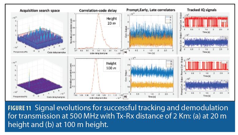
The highest and lowest received signal powers for the traditional building at the indoor location and 2 km Tx-Rx distance are -59 dBm and -61 dBm, -81 dBm and -98 dBm, -85.9 dBm and -94 dBm at 133, 401.5 and 500 MHz, respectively. For the thermal-efficient building, the highest received signal powers at 590 m Tx-Rx distance are -50 dBm -70 dBm for 133 and 500 MHz, respectively. The highest received powers are obtained when the Tx (mounted on the drone) is at 120 m. As expected, the received powers at indoor locations are lower than outdoor locations. A better signal power is generally observed at higher heights due to the decreased presence of low-height obstacles (vegetation, foliage, buildings). Figure 11 shows visual comparisons of signal noise during acquisition, tracking and demodulation when the signal is transmitted with 500 MHz at 20 m and 100 m height where the Tx-Rx distance is 2 km. Figure 11 also illustrates that transmissions at 100 m experience lower signal noise than those at low height.
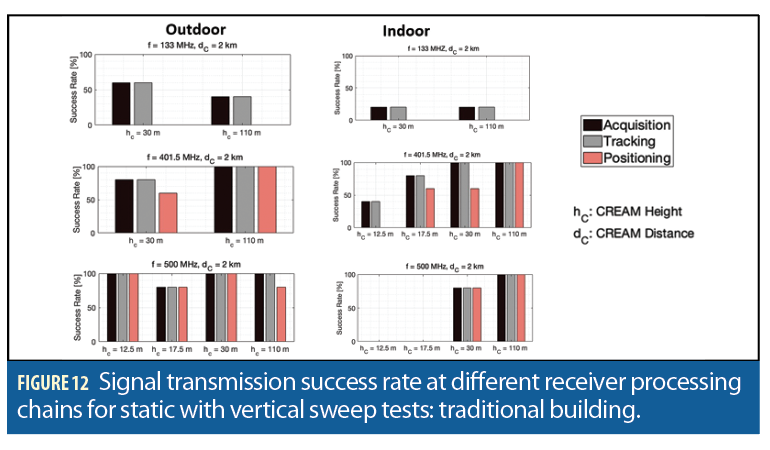
The success rates of the transmission for the traditional building for each receiver block processing at different Tx-Rx positions and frequencies are shown in Figure 12. For 133 MHz, the transmissions are nearly unsuccessful due to antenna and propagation limitations. For 401.5 and 500 MHz, the transmissions were mostly successful, especially at a high Tx (CREAM) position because there are fewer blockades. The transmissions at 500 MHz have the best performance. From Figure 12, it is clear transmissions at 12.5 m height have significantly higher failure rates compared to transmissions at > 20 m height due to obstacles imposing high signal attenuations up to below the Low-RF system sensitivity. It is worth noting that demodulation processes are also affected by near-far effect caused by multiple transmitters at different distances.
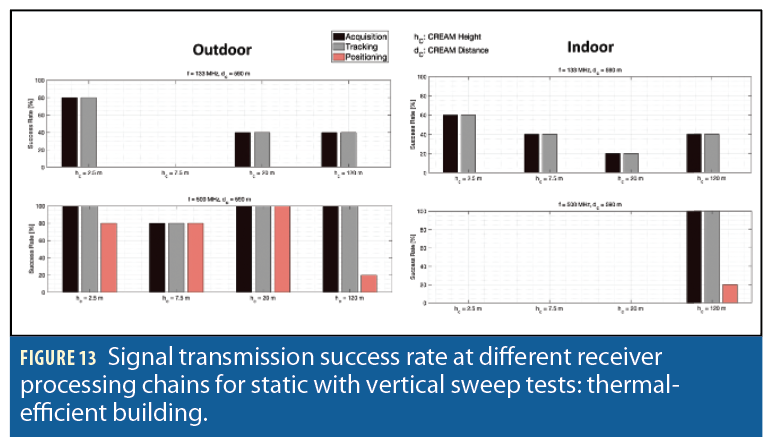
Results of the transmission tests for the thermal efficient buildings are shown in Figure 13. Like the traditional buildings, the transmissions at 133 MHz are not effective. However, transmissions at 500 MHz have a high success rate. For transmissions where the Tx is at low height and the Rx is outdoor, the transmission success rate is significantly lower than the results at > 20 m, due to signal attenuations introduced by the surroundings and the building materials. For transmissions where the Rx unit is indoor, only transmissions from the Tx unit at 120 m height maintain the success rate. Note the demodulation success rate of the transmissions at 120 m for both outdoor and indoor is low. However, because the acquisition and tracking processes are mostly successful, the failure of demodulation is caused by bit flipping. This could be corrected by implementing error correction techniques to improve the demodulation success rate. We found the transmitter CPU computational capacity limits the implementation of such techniques.
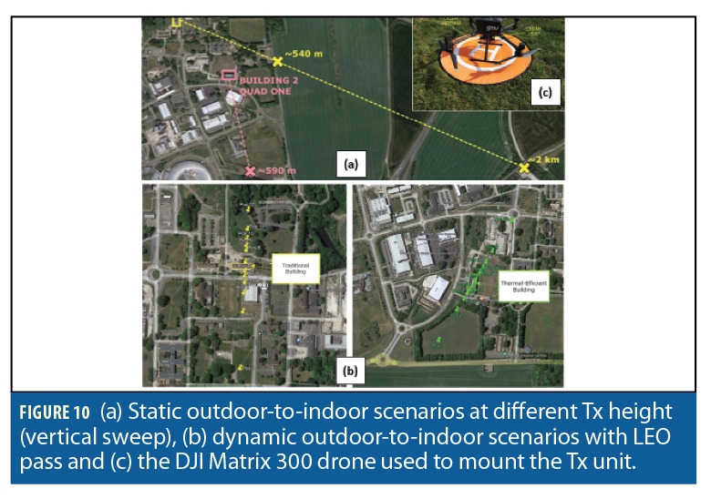
Dynamic outdoor-to-indoor transmission: LEO-pass trajectory
This test analyzes the Low-RF system performance under LEO satellite trajectories. The LEO satellite orbit pass is emulated by flying a UAV, carrying the Tx unit, at 40 m height in a straight line passing over the two buildings and by covering elevation angle α = [10°, 170°] as shown in Figure 10b. Thirteen positions were used to emulate the pass of a LEO satellite over the two buildings. For the traditional building, the Rx unit was located in four different positions: outdoor, indoor—first floor, indoor—first floor, and indoor—second floor. For the thermal-efficient building, the Rx unit is located at two locations: outdoor and indoor positions.
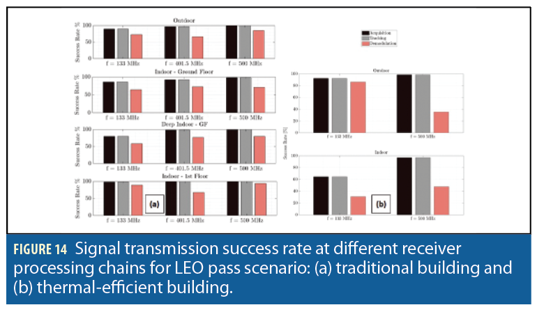
The transmission results for the emulated LEO orbit experiments passing the traditional and thermal-efficient buildings are shown in Figure 14a and 14b. In Figure 14a, the Low-RF system performance for the traditional building has the best performance at 500 MHz, with an acquisition and a tracking success rate of nearly 100%. The demodulation success rate was about 80% for all four positions. At 401.5 MHz, the demodulation success rate is slightly lower than others. That may be caused by interference with other signals at the frequency. The worst performances were at 133 MHz (especially at the indoor ground floor). This is not the design frequency of the antenna set, so signals are transmitted with less power. The thermal-efficient building had a success rate of nearly 100% for acquisition and tracking and about 30 to 50% for demodulation at 500 MHz. Regarding demodulation, due to less received power (large noise) at the Rx unit in the thermal-efficient building, the bit flipping percentage is higher than in traditional buildings. Again, one way to improve the demodulation process is to implement error-correcting techniques (channel coding) in Tx-Rx signals.
When it comes to received powers for experiments at the traditional building, the highest power is at outdoor locations and the lowest at the indoor ground floor, as expected. The highest and lowest received powers are -20 dBm and -55 dBm, -35 dBm and -75 dBm, and -45 dBm and -85 dBm, and for frequency 133, 401.5 and 500 MHz, respectively. The highest received powers are mostly at elevation angles between 10° and 60° where transmitted signals can reach the Rx through windows, thus without suffering wall attenuation. For the thermal efficient building, the highest (outdoor) and lowest (indoor) received powers correspond to -22 dBm and -55 dBm, -30 dBm and -75 dBm, and for frequency 133 and 500 MHz, respectively. Similar to the traditional building, the highest received powers are mostly at elevation angles between 10° to 60°.
From the received Rx power from the LEO pass experiment emulated by the flying drone at 40 m, the power loss from LEO satellites can be extrapolated by an extra path loss factor to account for the expected propagation from a LEO satellite flying at 500 km. By taking into account the realistic elevation geometry and distance (with respect to the emulated LEO-pass test), the extrapolation of the Rx power from LEO orbit is calculated as: received Rx power (at 40 m, elevation angle) – 20×log10 (distance between the Tx to LEO, elevation angle). From the extrapolation, all estimated received LEO RF power levels would be above the sensitivity of an ideal GPS L1 C/A receiver with processing gain PG = 25 dB (-158.5 dBm). All estimated values are based on the Tx-Rx parameters presented in Table 3.
Conclusion and Future Work
The Low-RF system, based on a single Tx-Rx communication link, has successfully demonstrated possible outdoor-to-indoor transmissions both in static and dynamic modes. Promising results were obtained from transmissions at 133 MHz, 401.5 MHz and 500 MHz. With the combination of explored hardware and considered experimental scenarios, the best signal propagation and navigation capabilities are obtained with the 500 MHz transmission. From the demonstration, the developed system, with navigation signals at low frequency (VHF-UHF frequency), efficient spread-spectrum signal structure and flexible Tx-Rx architectures can be used for a full CARS implementation and offers huge potentials for users such as emergency service responders. From real-world scenario experiments (vertical sweep and LEO pass), results show using low frequency signals for CARS is promising because of their improved penetration capability and ability to carry navigation information, which is critical in emergencies. From the results of the LEO pass experiments, it is possible to extract the feasibility of LEO-PNT systems making use of low-frequency transmissions.
Future works include extending transmission testing to other frequencies (C, S and high UHF band), testing in more scenarios (e.g. different types of buildings, urban cluttered areas, vegetations, Tx-Rx topologies and dynamic tests where the Rx moves), testing with different signal design and modulation, for example using a shorter PRN to reduce the spectrum bandwidth, and improving the Low-RF platform by using at least four Tx units, reducing the size, weight and power of the system and increasing the technology-readiness level (TRL) for deployment within an operational environment.
Acknowledgments
This work was supported by the European Space Agency (ESA) NAVISP program Element 1, which aims to innovate the technology of PNT systems. The work described was done under an ESA Contract. Responsibility for the contents resides in the author or organization that prepared it.
We would like to thank David Payne (GMV) who was the drone operator for the duration of the experimentation campaign, Aron Kisdi (GMV) who supported the drone experiments, Tim Whitworth and Yeqiu Ying who were involved in the technical activity at the early phase of this project and Filipa Fernandes for her contributions to reviewing the state of the art. Finally, we would also like to thank Mark Dumville (GMV) for his continuous support throughout the activity.
This article is based on material presented in a technical paper at ION GNSS+ 2022, available at ion.org/publications/order-publications.cfm.
References
(1) Huang, J.S. and Lien, Y.N., 2012, November. “Challenges of emergency communication network for disaster response”, IEEE International Conference on Communication Systems (ICCS), November 2012, pp. 528-532.
(2) Srinivasa, D., Pradep, P. D., Kumar, B. A., “Survey of Emergency Communication Network Architectures,” International Journal of u-and e-Service, Science and Technology, vol. 8, 2015, pp. 61-68.
(3) Nollet, K.E. and Ohto, H., “When all else fails: 21st century Amateur Radio as an emergency communications medium” Transfusion and apheresis science, 49(3), 2013, pp.422-427.
(4) Kunavut, K., “An Overview of Digital Trunked Radio: Technologies and Standards.” Journal of Industrial Technology, 10 (2), 2014, pp.111-121.
(5) FirstNet Authority report, “Understanding the FirstNet Deployable Program High-impact solutions for public safety operations,” 2021, USA.
(6) Mounir, T.A., Samia, M., Mohamed, S. and Bouabdellah, K., “A routing Ad Hoc network for disaster scenarios.” 1st International Conference on Information and Communication Technologies for Disaster Management, pp. 1-8, 2014, March.
(7) Rengaraju, P., Sethuramalingam, K. and Lung, C.H., “Providing Internet Access for Post-Disaster Communications using Balloon Networks.” Proceedings of the 18th ACM Symposium on Performance Evaluation of Wireless Ad Hoc, Sensor, & Ubiquitous Networks, pp. 111-117, 2021, November.
(8) Kishorbhai, V.Y. and Vasantbhai, N.N., “AON: a survey on emergency communication systems during a catastrophic disaster.” Procedia computer science, 115, 2017, pp.838-845.
(9) Portmann, M. and Pirzada, A.A., “Wireless mesh networks for public safety and crisis management applications.” IEEE Internet computing, 12(1), 2008, pp.18-25.
(10) Huang, J.S. and Lien, Y.N., “Challenges of emergency communication network for disaster response.” IEEE International Conference on Communication Systems (ICCS), 2012, November, pp. 528-532.
(11) Hussain, S.A., Ahmad, N., Latiff, L.A., Ahmed, S.B.M. and Mohamed, N., “Disaster Area Network Expansion Using Drones Based Ad-hoc Cellular Communications.” IEEE Symposium On Future Telecommunication Technologies (SOFTT), pp. 22-27, 2021, December.
(12) Shamsoshoara, A., Afghah, F., Blasch, E., Ashdown, J. and Bennis, M., “Uav-assisted communication in remote disaster areas using imitation learning.” IEEE Open Journal of the Communications Society, 2, 2021, pp.738-753.
(13) Wang, Y., Su, Z., Zhang, N. and Fang, D., “Disaster Relief Wireless Networks: Challenges and Solutions.” IEEE Wireless Communications, 28, 2021, pp.148-155.
(14) Fodor, G., Parkvall, S., Sorrentino, S., Wallentin, P., Lu, Q. and Brahmi, N., “Device-to-device communications for national security and public safety.” IEEE Access, 2, 2014, pp.1510-1520.
(15) Chu, Z., Le, T.A., Nguyen, H.X., Nallanathan, A. and Karamanoglu, M., “A stackelberg-game approach for disaster-recovery communications utilizing cooperative D2D.” IEEE Access, 6, 2017, pp.10733-10742.
(16) European Global Navigation Satellite Systems Agency, “What is GNSS?” link: https://www.euspa.europa.eu/european-space/eu-space-programme/what-gnss#:~:text=Global%20Navigation%20Satellite%20System%20(GNSS,definition%2C%20GNSS%20provides%20global%20coverage.
(17) U.S. Department of Defense, “GPS Standard Positioning Service (SPS) Performance Standard,” GPS NAVSTAR, 2008.
(18) European Space Agency, “GLONASS Space Segment,” ESA Navipedia, 2018.
(19) European Global Navigation Satellite Systems Agency, “Galileo: the European global satellite-based navigation system,” European GSA Online, 2018.
(20) China Satellite Navigation Office, “BeiDou System Overview,” 2018
(21) Brena, R.F., García-Vázquez, J.P., Galván-Tejada, C.E., Muñoz-Rodriguez, D., Vargas-Rosales, C. and Fangmeyer, J., “Evolution of indoor positioning technologies: A survey.” Journal of Sensors, 2017.
(22) Karunatilaka, D., Zafar, F., Kalavally, V. and Parthiban, R., “LED based indoor visible light communications: State of the art.” IEEE communications surveys & tutorials, 17(3), 2015, pp.1649-1678.
(23) Haruyama, S., “Visible light communications.” In 36th European Conference and Exhibition on Optical Communication, 2010, September, pp. 1-22.
(24) Ijaz, F., Yang, H.K., Ahmad, A.W. and Lee, C., “Indoor positioning: A review of indoor ultrasonic positioning systems.” 15th International Conference on Advanced Communications Technology (ICACT), 2013, pp. 1146-1150).
(25) Li, K., Gong, Q., Ren, Y., Li, Y., Han, Y., Pang, C. and Kong, H., “Magnetic Field Positioning Technology of Indoor Sports Bodies.” IEEE Sensors Journal, 22(1), 2021, pp.219-228.
(26) Holloway, C.L., Koepke, G., Camell, D., Remley, K.A., Williams, D.F., Schima, S.A., Canales, S. and Tamura, D.T., “Propagation and detection of radio signals before, during, and after the implosion of a 13-story apartment building,” National Institute of Standard Technology Note, 2005, 1540.
(27) Wassie, D.A., Rodriguez, I., Berardinelli, G., Tavares, F.M., Sørensen, T.B., Hansen, T.L. and Mogensen, P., “An agile multi-node multi-antenna wireless channel sounding system,” IEEE Access, 7, 2019, pp.17503-17516.
(28) He, J., Zhou, S.Q., Liao, K., Wei, X.C. and Li, E.P., “Radio frequency propagation characteristics in disaster scenarios,” In Proceedings of 2014 3rd Asia-Pacific Conference on Antennas and Propagation, 2014, July, pp. 818-821.
(29) 3GPP, “Study on channel model for frequencies from 0.5 to 100 GHz (Release 15),” 3GPP TR 38.901, 2018.
(30) European Cooperation in Science and Technology, “Evolution of Land Mobile Radio,” COST 231, Final Report, 1999.
(31) 3GPP, “Study on New Radio (NR) to support non terrestrial networks (Release 15),” 3GPP TR 38.811, 2018.
(32) Rodriguez, I., Nguyen, H.C., Sørensen, T.B., Zhao, Z., Guan, H. and Mogensen, P., “A novel geometrical height gain model for line-of-sight urban micro cells below 6 GHz,” In 2016 International Symposium on Wireless Communication Systems, 2016, September,pp. 393-398.
(33) Colpaert, A., Vinogradov, E. and Pollin, S., “Aerial coverage analysis of cellular systems at LTE and mmWave frequencies using 3D city models,” Sensors, 18(12), 2018, p.4311.
(34) Rodriguez, I., Nguyen, H.C., Kovács, I.Z., Sørensen, T.B. and Mogensen, P., “An empirical outdoor-to-indoor path loss model from below 6 GHz to cm-wave frequency bands.” IEEE antennas and wireless propagation letters, 16,2016, pp.1329-1332.
(35) International Telecommunications Union, “Effects of building materials and structures on radiowave propagation above about 100 MHz,” ITU-R Rec. P.2040-1, 2015.
(36) Koppel, T., Shishkin, A., Haldre, H., Toropovs, N., Vilcane, I. and Tint, P., “Reflection and transmission properties of common construction materials at 2.4 GHz frequency,” Energy Procedia, 113, 2017, pp.158-165.
(37) William, C.S., Gary, R.B. and Robert, E.H., “Electromagnetic signal attenuation in construction materials” USA: National Institute of Standards and Technology, 1997.
(38) Misra, P, Enge, P., “Global Positioning System: Signals, Measurement and Performance,” 2nd Edition, 2006, Ganga-Jamuna Press: USA.
(39) Gallager, R.G., “Principles of digital communication,” 2008, Cambridge: Cambridge University Press.
(40) https://www.ettus.com/all-products/usrp-e312/. Accessed: 20 June 2022.
(41) https://www.ettus.com/all-products/x310-kit/. Accessed: 20 June 2022.
Authors
Wahyudin P. Syam holds a Ph.D. in geometrical measurement and uncertainty analysis from Politecnico di Milano in Milan, Italy. After finishing his Ph.D., he held a post-doctoral research position at the University of Nottingham for five years, where he gained experience in machine learning for measurement and image analysis and hardware-interfacing programming. He joined GMV in February 2021.
David Scott received his MEng in Electrical and Electronic Engineering from Newcastle University in 2019. He has worked at GMV since graduation, where he is involved in several projects related to low frequency communications and alternative PNT solutions. He holds extensive experience in the manipulation of software defined radio (SDR) devices, including universal hardware driver (UHD), libIIO and GNURadio. He also has experience with embedded microcontroller programming in multiple architectures.
Alejandro Pérez Conesa received his B.Sc. degree in computer engineering and his B.Sc. and M.Sc. degrees in telecommunication engineering from the Universitat Autònoma de Barcelona (UAB) in 2018, 2019 and 2020, respectively. He is Project Manager for GMV and an Adjunct Professor at UAB. He worked as research engineer for the Signal Processing for Communications and Navigation (SPCOMNAV) group at UAB in 2019 and 2020 and as GNSS Technical Lead for Indra in 2020 and 2021. He has been involved in numerous activities funded by the European Space Agency (ESA) and other international entities.
Ignacio Rodríguez received B.Sc. and M.Sc. degrees in telecommunication engineering from University of Oviedo, Spain, and a M.Sc. degree in mobile communications and the Ph.D. degree in wireless communications from Aalborg University, Denmark. He is a Ramón y Cajal Research Fellow at University of Oviedo, Spain. Previously, he was an Assistant Professor at Aalborg University, Denmark, where he led the 5G for Industries Research Group; and an External Research Engineer with Nokia Bell Labs, where he was involved in 3GPP and ITU-R standardization activities. He was a co-recipient of the IEEE VTS 2017 Neal Shepherd Memorial Best Propagation Paper Award, and in 2019, was co-awarded the 5G-prize by the Danish Energy Agency and the Danish Society of Telecommunication Engineers.
Melisa López Lechuga received a B.Sc. and M.Sc. in telecommunications engineering from Universitat Politécnica de Catalunya, Spain, in 2016 and 2018, respectively. In 2022, she received a Ph.D. in wireless communications from Aalborg University, Denmark, where she is currently a postdoctoral researcher.
Enric Juan Martinez received a B.Sc. and M.Sc. in telecommunications engineering from Universitat Politécnica de Catalunya, Spain, in 2015 and 2018, respectively. He is currently pursuing a Ph.D. in wireless communications at Aalborg University, Denmark, in collaboration with Nokia, Aalborg, Denmark.
Rigas Themistoklis Ioannides received a B.Eng degree in electronic engineering from the University of Lancaster, Lancaster, UK, in 1995, a M.Sc degree on “Communication and Real Time Electronic Systems” from the University of Bradford, Yorkshire, UK, in 1997, and a Ph.D. from the University of Leeds, Leeds, UK, on modelling and correcting of ionospheric effects on GPS signals in 2002. He joined the European Space Agency in 2010. From 2014, he supported the Galileo Program on the definition and design of the Public Regulated Service. He joined the Galileo Second Generation in 2018, leading the design on OS Authentication techniques. In 2021 he joined the GNSS system Evolutions section under the Horizon Europe Program.


