
Authors develop and demonstrate a receiver agnostic, real-time signal cleaner that uses innovative, efficient algorithms as well as machine learning methods.
WAHYUDIN P. SYAM,* NABEEL ALI KHAN,* MICHAEL TURNER, LUIS ENRIQUE AGUADO,
BEN WALES, LISA GUERRIERO, BARIS TOZ, INCHARA LAKSHMINARAYAN, TOM STACEY,
MARIA IVANOVICI, TERRI RICHARDSON, GMV
GNSS has provided global positioning, navigation and time (PNT) solutions for many application domains covering safety critical, liability critical and commercial applications. However, because of the relatively low-power signal around -128 dBm and the openness of the signal structures, GNSS signals are vulnerable to jamming and spoofing attacks [1,2]. These attacks significantly disrupt GNSS services, making them unavailable or producing invalid PNT solutions that might cause severe impacts on assets or people using the services. There are various well-known interference and jamming attacks including broadband (such as CDMA) jamming, frequency-hopping jamming, narrow-band jammer, and frequency-sweep or chirp (and pulsed chirp) jamming attacks as well as spoofing attacks ranging from a brute force spoofer transmitting GNSS-like signals at higher power, to meaconing (replay), to aligned or overlapping and sophisticated spoofing attacks [3]. Interference could be non-intentional, such as frequency interference from communication signals, or intentional, such as chirp jamming. Spoofing attacks are most likely intentional. With the growing capability and affordability of software-defined radio (SDR) and advanced spoofing generation algorithms, spoofing attacks have become more significant. Because of this, there is a need to develop a receiver-agnostic and flexible signal cleaner system to increase the resilience of GNSS services in vulnerable environments threatened by GNSS interference and spoofing.
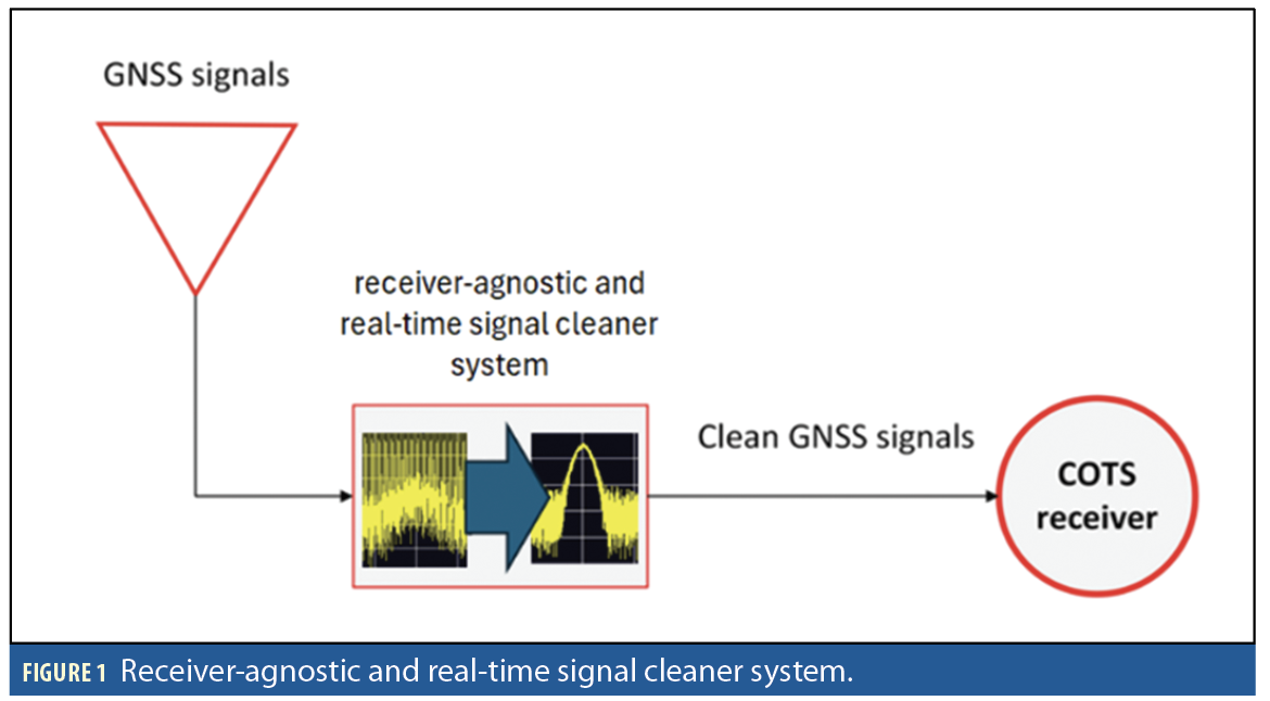
This article aims to develop and demonstrate a receiver-agnostic, real-time signal cleaner system that uses innovative and efficient algorithms for detecting, characterizing and mitigating jamming and spoofing signals. For spoofing, the mitigation focuses on overlapping (aligned) spoofing attacks on the GPS L1 C/A signal. Figure 1 shows the schematic view of the signal cleaner system. In this system, the developed jamming and spoofing detection and mitigation algorithms use optimized signal processing techniques and advanced machine learning algorithms. The system is configurable and uses commercial-off-the-shelf (COTS) components including a GNSS antenna, a high-performance computer for real-time jamming and spoofing detection and mitigation processing, a radio-frequency front-end to receive and transmit GNSS signals, and a downstream commercial receiver to receive and process the mitigated/cleaned signal from the system. The system can operate in real-time up to a 20MHz sampling rate and is designed for flexibility, allowing for seamless integration between a GNSS antenna and a receiver without modifications to the receiver’s existing infrastructure.
Jamming Detection and Mitigation
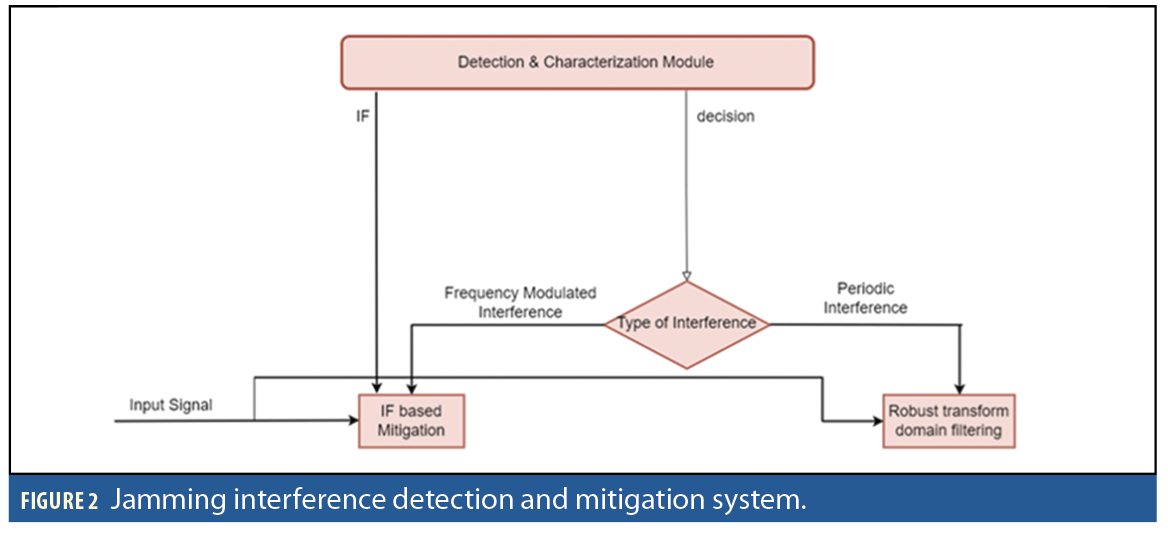
The overall jamming detection and mitigation system is composed of two modules a) an interference detection module and b) an interference mitigation module (Figure 2).
Jamming Detection and Characterization
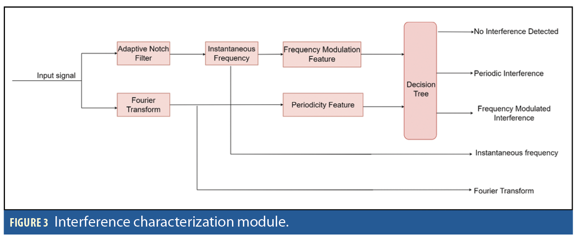
The interference detection and characterization system extract a) periodicity detection feature and b) frequency modulation features from a segment of received signal to detect and characterize interference (Figure 3).
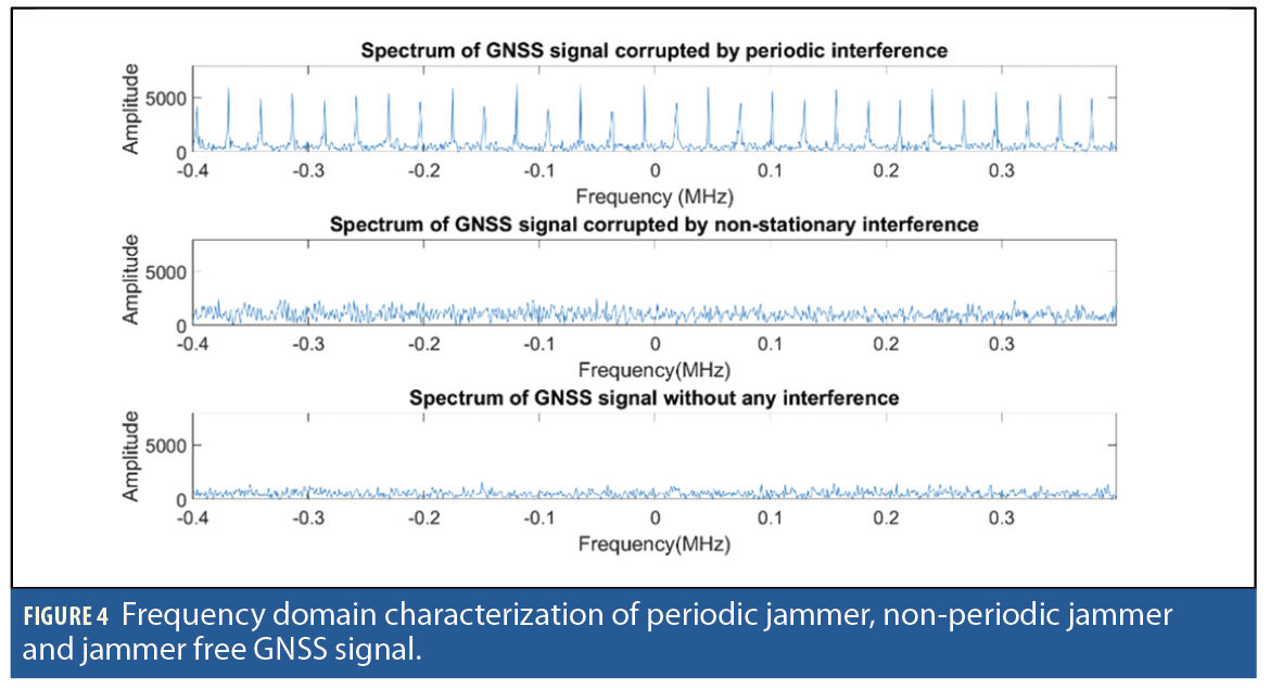
Periodicity Detection Feature: The periodicity check is performed to analyze whether the interfering signal is periodic (x[n]=x[n+K]) or aperiodic. A chirping signal can become a periodic signal if the same sequence is repeated over time. However, this is not always the case. In periodic interference, the interfering signal becomes sparse in the frequency domain and appears as a train of impulses (Figure 4).
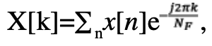
To find out whether the interfering signal is periodic or non-periodic, we first transform a given signal of NF samples in the frequency domain as X[k]=∑nx[n]e. The parameter NF is based on the periodicity interval, i.e., K of the interference signal. It should be at least 8 times the periodicity interval of the interference signal, NF>8K. We detect a M number of strong peaks from the |X[k]|2 and store them in Y[k]. The periodicity detection feature is defined as:
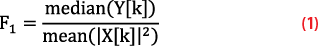
In case of periodic interference, F1 has a higher value whereas for non-periodic interference or noise, F1 has a lower value.
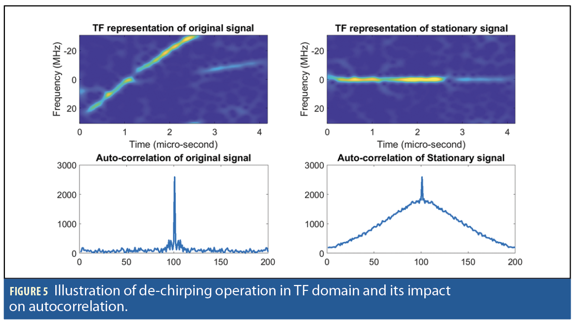
Frequency Modulation Feature: Frequency modulated jammers are modeled as J(t)=Ae(j∫f(τ)dτ), where A is the signal amplitude and f(t) is the instantaneous frequency (IF). To extract the frequency modulation feature, we first employ the adaptive notch filter (ANF) to track the IF curve. The IF information is then used to de-chirp J(t) and the frequency modulation detection feature is extracted based on its covariance matrix.
The steps to estimate the frequency modulation feature are:
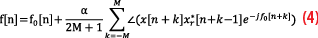
IF estimation: The IF is defined as derivative of the phase of the incoming signal, implying it can be simply estimated as: f0[n]=∠x[n]x*[n-1]. The ANF based IF estimation method adopts a recursive approach where a past estimate of the IF is used as a predicted value and phase difference between the current sample of signal and past sample of its bandpass filtered version are employed to correct the predicted IF [4]:

Where u is update rate, xr [n] is bandpass filtered signal obtained by placing pole close to f0[n] that suppresses out of the band noise:

Where kα is filter bandwidth of the control parameter.
Once crude IF is estimated, the refined estimate is obtained by using f0[n] as the predicted value and performing correction based on the moving average of the phase differences of x[n] and xr [n-1] as discussed in [4]:
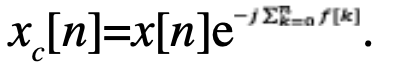
Feature Extraction: Once the IF is estimated, the corresponding instantaneous phase is estimated as: . The estimated instantaneous phase is used to de-chirp the signal as xc[n]=x[n] e-j[n]. This de-chirped signal now has high temporal correlation (Figure 5).
The covariance matrix of xc[n] is computed as:
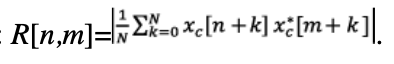
In case of a frequency modulated jamming signal, all the elements of R[n,m] will have values significantly greater than zero whereas for GNSS signals, non-diagonal elements would be close to zero. So, the ratio of the sum of diagonal elements of R[n,m] versus the sum of all the elements can be used as a test statistic [4] of F2 and will have a higher value for pure GNSS signal and a lower value for GNSS signals corrupted by noise, as follows:
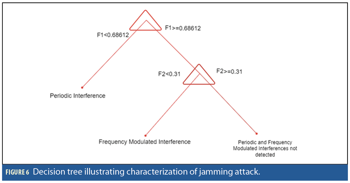
Decision Tree based Classification: We trained a machine learning classifier to solve a multi-class classification problem: detecting periodic and frequency modulated interferences. The training dataset is generated by adding interferences to recorded GNSS signals of 100ms duration and 15MHz bandwidth. The following type interferences are used to train the classifier, which are chirp type non-stationary interference and periodic interference. The decision tree is trained using the frequency modulation feature and periodicity feature for the following classes: (1) Periodic interference, (2) Frequency modulated interference and (3) Interference free GNSS signal. The decision tree is presented in Figure 6.

Jamming Mitigation
The interference mitigation unit employs the outputs of the detection module to select the type of mitigation to be performed. If the interference is frequency modulated, then the IF-based interference mitigation is employed. However, if the interference is classified as periodic interference, e.g., narrow band or CDMA type, then the robust transform domain filtering is employed. If a signal is periodic in the time-domain, e.g., CDMA signal, with period T, then its frequency domain representation becomes sparse with frequency components appearing only at integer multiples of 1/T, (Figure 7). Such interference can be easily removed by applying non-linearity in the frequency domain.
The periodic interference mitigation methods are mentioned in the following steps:
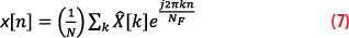
1. Transform a signal into frequency domain as
where NF is the number of samples in the signal. To effectively mitigate the interfering signal, NF needs to have a higher value as it provides higher frequency resolution to identify bins corresponding to interfering signal.
2. Apply Huber’s non-linearity:

3. Inverse transform the signal into time domain as:
Th is a data dependent threshold that is selected so most of the signal energy is passed undistorted and only bins corresponding to the interference are saturated. We know most of the desired signal energy is less than μ+2σ where μ is the mean of |X[k]| and σ is its standard deviation. The strong interference appears as spikes in frequency domain that may bias the estimate of μ and σ, so we use the median in place of mean and median absolute deviation in place of σ. So, the threshold is computed as: T=median (|X[k]|)+2 median (||X[k]|–median (|X[k]|)|).
Frequency modulated interference mitigation is as follows. If frequency modulated interference is detected, then zero-phase notched filter is applied as in [4]:
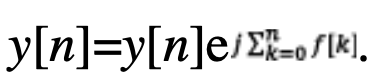
• The signal is de-chirped as:
• The notch filter is applied as: g[n]=βg[n-1]+xc[n]-xc[n-1]
• The output of the notched filter is flipped: [n]=g[-n]
• The notch filter is applied again:[n]=kα
[n-1]+[n]-[n-1].
• The output is flipped yc[n]=[-n]
• The filtered signal is then chirped again:
Note that unlike the conventional ANF that performs mitigation online on a sample-by-sample basis, this method processes stored buffer of sample in both directions. This forward and backward filtering overcomes the non-linear phase distortions common in the conventional ANF.
Spoofing Detection and Mitigation
Spoofing Detection
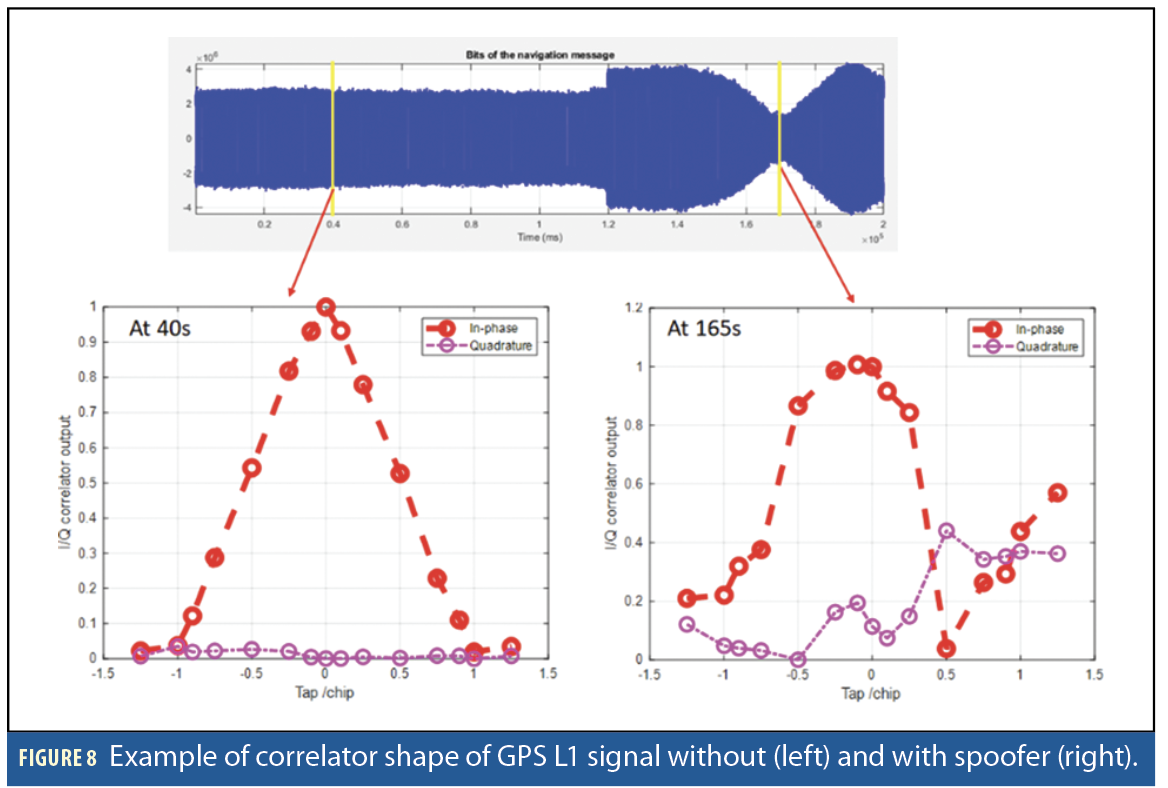
The method of spoofing detection and mitigation focuses on overlapping or aligned spoofing attacks where spoofers code delay is within ±1chip with an authentic signal. This aligned spoofing will significantly degrade the correlator shape of authentic signals and its local pseudorange (PRN) code [6]. Figure 8 shows examples of the correlator shape of an authentic and spoofed GPS L1 C/A signal. When there are no spoofers, the correlator shape is a triangle (at epoch 40s). However, the correlator shape is significantly distorted when an aligned spoofer presents (at epoch 165s). The total correlator taps for spoofing detection and mitigation is selected to be 15-tap considering the correlation resolution for spoofer estimation as well as computational load to satisfy real-time processing. The 15-tap correlators consist of seven taps for both late and early chips, and one tap for the prompt chip. Ideally, correlator tap resolution should be as high as possible to accurately estimate spoofer code delay for spoofing detection and mitigation. Table 1 shows the 15-tap selected to calculate correlation between the GPS signal and its local PRN code.
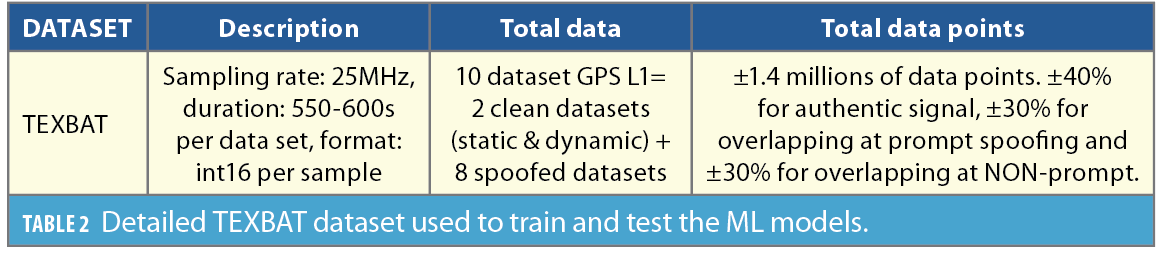
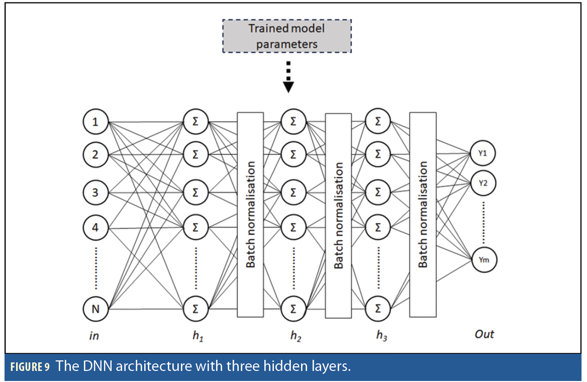
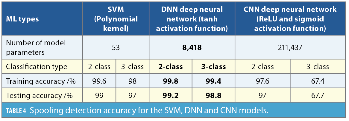
Spoofing detection is performed using a deep neural network (DNN) model [7] that was selected following a trade-off analysis among support vector machines (SVM) and convolutional neural networks (CNNs). The number of parameters of the three evaluated models are 53, 8,418 and 211,437 for SVM, DNN and CNN, respectively. The SVM model has the smallest model size that cause limitations on spoofing detection accuracy [8]. Meanwhile, the CNN, although capable of automatic feature extraction, has a large number of parameters, making training difficult [7]. The DNN model architecture, shown in Figure 9, is a fully connected feed forward neural network with three-hidden layers with tanh activation functions. The selection of this architecture is to trade-off between detection accuracy and detection speed. These models have been trained and tested with the TEXBAT spoofing dataset [9]. Table 2
presents the details of the dataset for training and testing the three ML models. Ten signals cover the clean and spoofed GPS L1 C/A signal.
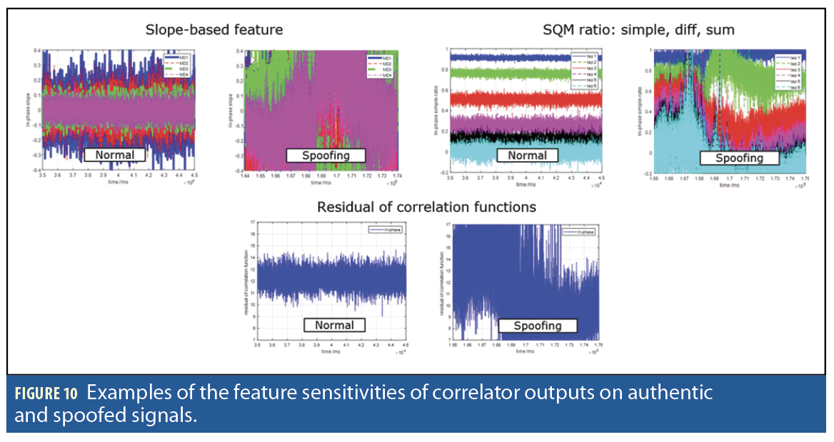
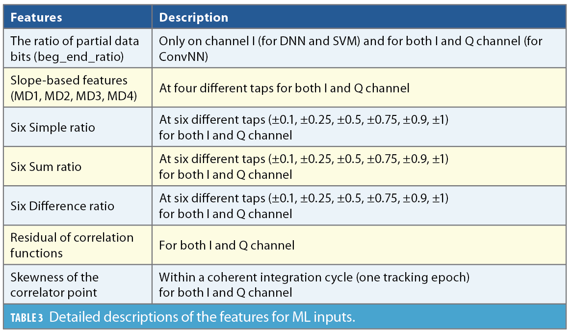
The inputs to the ML models are 50 calculated features extracted from the correlator outputs of both GNSS signals. These features include the ratio of partial data bits [10], slope-based ratios [11], simple ratios, sum ratios, difference ratios [12], residuals of correlation functions [6] and the skewness of correlator points. Table 3 details the description of the calculated features as inputs for the ML models.Figure 10 gives examples of the sensitivity of the features calculated on authentic signals and spoofed signals on the selected TEXBAT signal dataset. The calculated features can capture the degradation of correlator shapes calculated when overlapping or aligned spoofers exist (Figure 10).
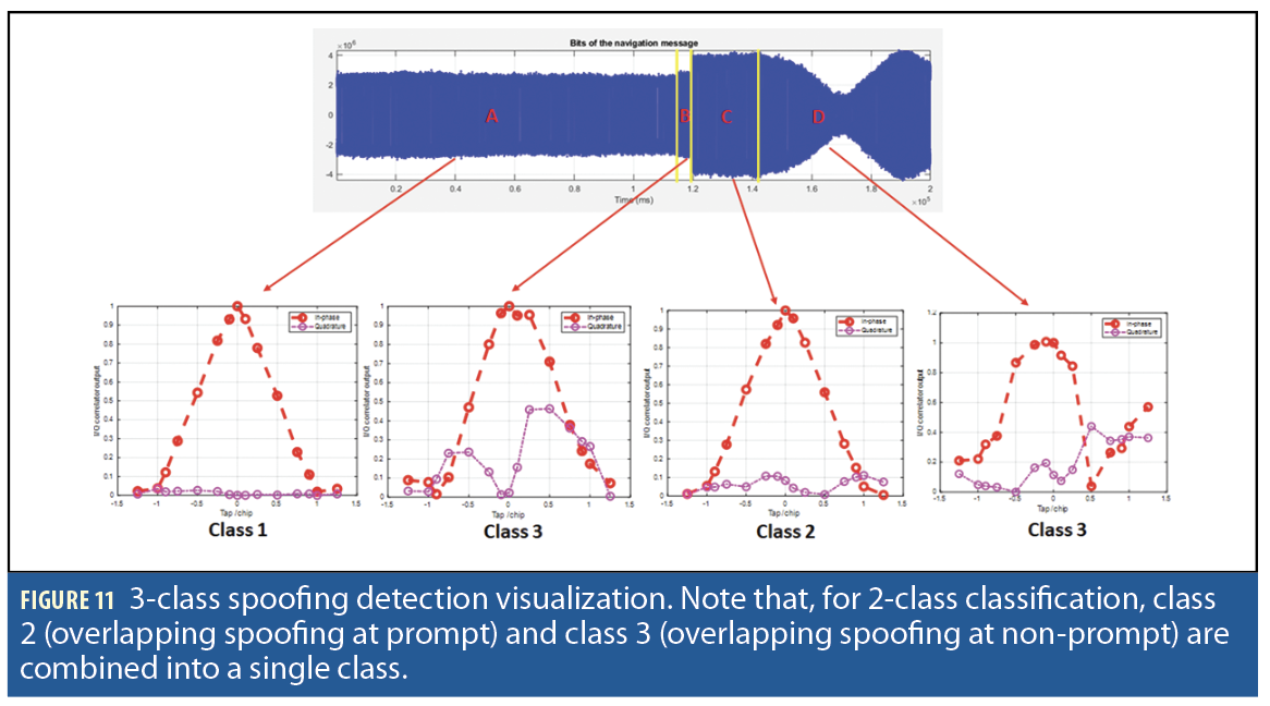
Spoofing detection is classified into 2-class and 3-class detection. Figure 11 shows the 3-class classification where a correlator output is detected as clean (class 1), overlapping at prompt tap (class 2), and overlapping at non-prompt tap (class 3). Meanwhile, 2-class classification only differentiates between clean (class 1) and spoofed situation (class 2+ class 3). Results of spoofing detection (Table 4) show that 3-class classification has lower detection accuracy than 2-class classification. The DNN model performance, with 3-class training and test accuracy of 99.4% and 98.8% respectively, is the best compared to the SVM and CNN model performance. The CNN, especially for 3-class classification, has the worst performance of training and testing accuracy of only 67.4% and 67.7%, respectively. That may be caused by insufficient data to train CNN large model capacity. Note the data for overlapping at prompt tap is much smaller compared to the other class, clean and overlapping at non-prompt tap.
A total of 200s durations of the clean signal in the TEXBAT data set is used to assess the false alarm rate because the spoofing detection is performed per tracking epoch with 1ms coherent integration time. There is a total of 200,000 data points for the false alarm assessment. The spoofing alarm is raised when there are 30 consecutive spoofing detections. When there is a 10ms duration of spoofing detection, a spoofing alarm rises. The false alarm rate is 0.009 for an open-sky signal with no or minimal multipath effect. For a signal with heavy multipath impairments, such as in dense urban areas, the false alarm rate degraded to 0.015. That’s because the overlapping spoofing phenomenon is like multipath phenomenon in terms of degradations of correlator output shapes.
Spoofing Mitigation
The spoofing mitigation method focuses on recovering an authentic GPS L1 C/A signal from an aligned match-power spoofing attack instead of canceling the signal. The spoofing mitigation algorithm uses an impulse method to calculate the second gradient of correlator outputs of GNSS signals to estimate the code delay of authentic and spoofer signals based on the two largest gradient impulses. The final estimated second-gradient impulse is calculated as a weighted average of three neighbor impulses. In addition, using these impulses, the spoofer’s power and phase are estimated. Subsequently, a negative replica of the spoofer signal is generated and subtracted from the original signal (containing both the spoofer and authentic signals). This subtraction process effectively removes the spoofer signal, isolating the authentic signal component.
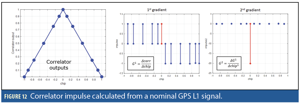
The impulse is the second gradient of correlator outputs. The first G1 and second gradient G2 (the impulse) are calculated as follows:
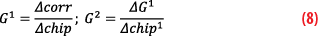
Where Δcorr is the difference between two consecutives correlator outputs and Δchip is the difference between the two consecutive chips. ΔG1 is the difference between two consecutives first gradient G1 outputs and Δchip1 is the difference between the two consecutive chips after the G1 calculation.
The accuracy of spoofer parameter estimation, especially the spoofer code delay, highly depends on the chip tap resolutions. Small chip tap distance will have high accuracy estimation. However, the smaller the chip tap distance (high accuracy detection), the higher the sampling frequency required. There is a trade-off between high accuracy spoofer parameter estimations and computational requirements to process the sampled signal. Because the numbers of 15-tap correlators are considered sparse, we need to improve and smooth the code-delay estimation by using a weighted-average method. The final estimated code delay (tap location) is:
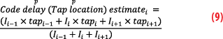
Where Ii is the 2nd gradient impulse at the i-th tap index and Tapi is the i-th tap index. In short, the refined estimate of the code delay or tap location is based on the neighbor’s 2nd gradient impulse at the tap location to be refined. The spoofer is identified as the largest impulse from the two largest gradient impulses.
From these two decomposed signals, we estimate the spoofer’s power and the IQ carrier phase rotation. The power and IQ rotation θ estimation are as follows:

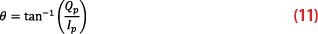
Where Ip and Qp are the I and Q correlator output at the p-th tap location (code delay) estimated by the weighted-average of the 2nd gradient impulse. Poweradjustment is the adjusted power for each decomposed signal that is the ratio of its 2nd gradient impulse over the total summation of the two highest 2nd gradient impulse (impulsei, impulsej).
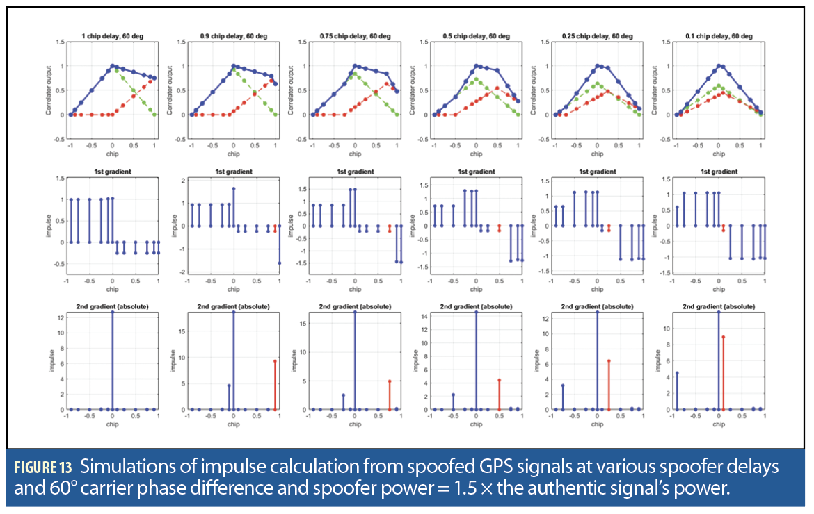
Figure 12 presents the impulse from 15-tap correlator outputs calculated from a nominal GPS L1 signal. In nominal conditions, the highest impulse (2nd gradient) will be at the prompt tap. Simulations of impulse calculation from spoofed GPS signals at various spoofer delays and 60° carrier phase difference between the authentic and spoofer components are shown in Figure 13. The spoofer power is set to be 1.5 × the authentic signal’s power.
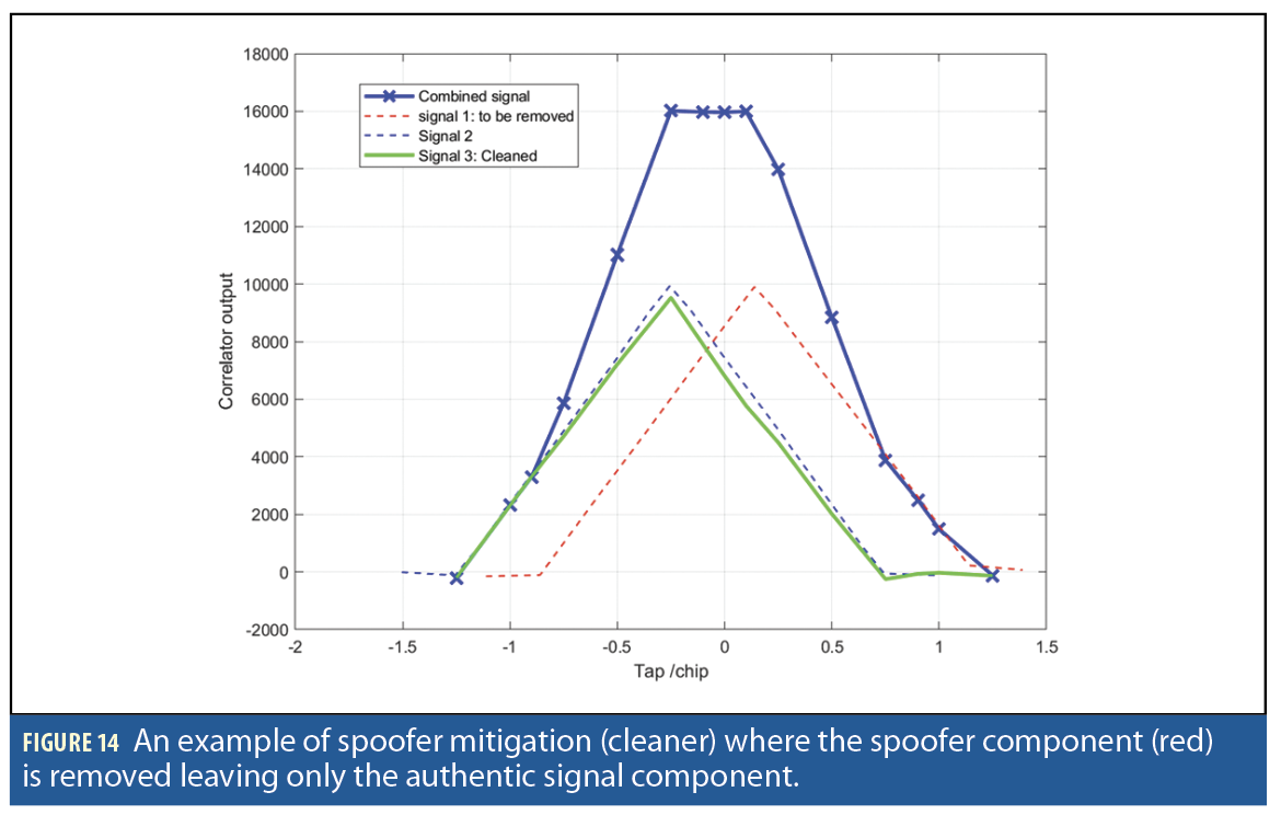
Figure 14 shows a simulated GPS L1 C/A spoofed signal, containing authentic and spoofer components, and the implementation of the spoofer mitigation (cleaner) processes where the spoofer component (red) is removed leaving only the authentic signal component (green). The effectiveness of the mitigation depends on how distorted the signal correlator is. To evaluate the mitigation performance, the mitigation method is applied to different tracking epoch (1ms) to TEXBAT dataset signals at different C/N0. The C/N0 is used as the signal quality measure.
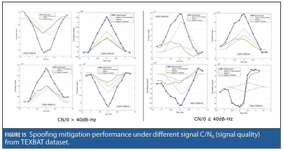
Figure 15 illustrates spoofing mitigation performance under different signal C/N0. From performance test results, the spoofing mitigation can faithfully remove spoofer components and restore authentic components when the C/N0 is > 40dB-Hz. When the signal has C/N0 of < 40dB-Hz, the correlator shape distortion is too large, so we cannot faithfully estimate the spoofer parameters and remove the spoofer components.
Implementation of a Receiver-Agnostic, Real-Time Signal Cleaner
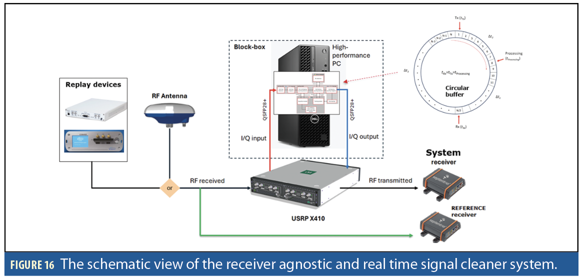
Implementing the signal cleaner fully uses the real-time software approach under the Linux operating system. The main processing unit is a high-performance PC with a multi-core processor. A multi-threading method is used to increase computational speed. However, the processing limitation is the interconnection among multi-cores inside the processor that allows only 40% of the total cores (40 cores) to be used. These internal multicore bottlenecks limit the maximum sampling frequency to operate at 20MHz. Figure 16 shows the schematic view of the developed signal cleaner system. Two receivers are used: “system” and “reference” receivers. The “system” receiver receives the signal after it’s processed by the system and the “reference” signal receives the signal directly from the GNSS antenna used for comparison. A circular buffer system continuously receives (RF), processes (IQ signal) and re-transmits (RF). We use three memory pointers to locate received, processed and transmitted data. In this buffering system, the processing time should be faster than the transmission time to make sure transmitted signal to a downstream receiver is continuous.
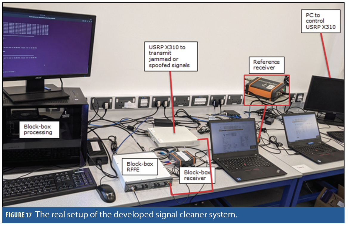
In summary, the final system building blocks consist of a GNSS RF antenna to capture RF GNSS signals (NavXperience 3G+C Reference with 49dB gain with power input < 50mA), RF front-end (RFFE) based on SDR USRP X410 for RF capture and RF reply of GNSS signals, a processing, including storage, unit to process GNSS signals and implement jamming and/or spoofing detections and mitigations (Intel® Core™ i7 20-Core Processor i7 and 64GB RAM) and a GNSS COTS receiver (Septentrio AsteRx SB3 Pro+) as the downstream receiver to process the cleaned signal and provide PVT solutions.
Figure 17 shows the system’s real setup. After characterizing the RFFE device, an important component, the receiver noise is quantified to be 144.8dBm/Hz. The signal dynamic range of the RFEE is 65-75dB-Hz. Meanwhile, the input power dynamic range (where GNSS signal can be faithfully received) of the RFFE is about 85dBm=–50dBm to 135dBm. The transmitter power output is about 17dBm (at 50dB gain) and, by assuming linearity, the power output is –23dBm (at 10dB gain) and at –33dBm (at 0 dB gain).
Experiment Results
The system is tested through experimental campaigns using real datasets obtained from Jammertest 2024 in Andøya, Norway (for jamming mitigation) and the TEXBAT dataset (for spoofing mitigation) by using a professional commercial GNSS receiver. The Jammertest dataset covers various types of jammers, including a low-powered chirp jammer, a ramp-up-and-down CDMA jammer, and a narrow-band jammer with a slow-varying center frequency.
Low Powered Jammer Attack
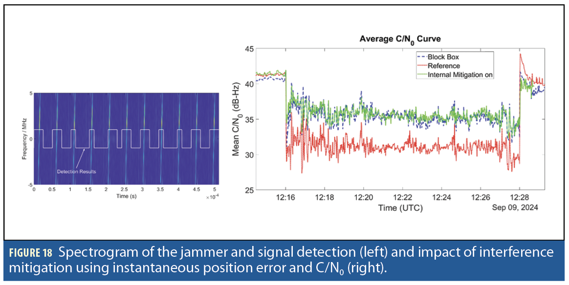
A low powered pulsed jammer (0.2W) with a clean first 90 seconds is replayed using a Spirent transmitter to both reference and develop a system receiver. Reference receiver performance was tested in two modes: a) internal mitigation on and b) internal mitigation off. Figure 18 (left) illustrates the signal detection performance as well as the Spectrogram of the jammed signal.
The interference observed in the given signal is pulsed interference. To evaluate the system’s interference characterization performance, we need to compare the system’s output with the ground truth. The interference appears only for a short duration and affects only a few samples, so we obtain the ground truth by dividing the signal into segments of 128 samples computing energy for each segment. If energy exceeds the manually adjusted threshold, interference is said to be detected in the segment. Otherwise, it’s not. The probability of detection by comparing the developed system output with an energy-based detector is 0.98 and the probability of false alarm is 0.08 if the complete signal is used for analysis. However, if we compute the probability of false alarm, the free part of the signal is 0.04. The performance comparison between the system and reference receiver is performed using average C/N0 (Figure 18, right).
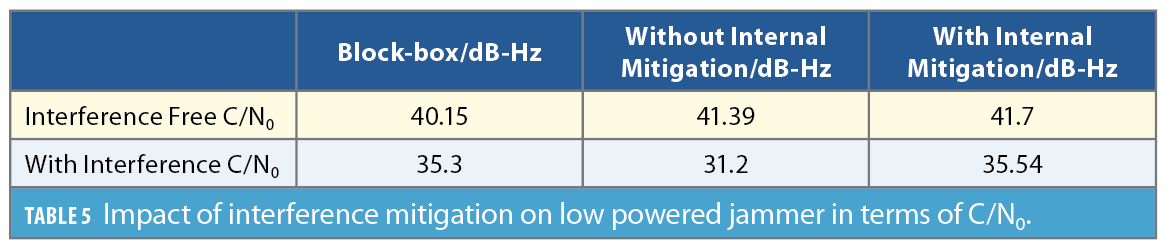
The interference mitigation results in an approximate 5 dB-Hz gain in C/N0. Results show internal mitigation offers a 0.25 dB advantage in terms of C/N0 as compared to block-box during the interference part of the signal. The block-box system itself introduces approximately 1.5 dB distortion in interference in the free part so the block-box algorithm will give approximately 1.25 dB gain if the block-box algorithm is implemented within the GNSS receiver. Table 5 summarizes the impact of interference mitigation on a low powered jammer in terms of C/N0.
Ramp-up Ramp-down jammer attack
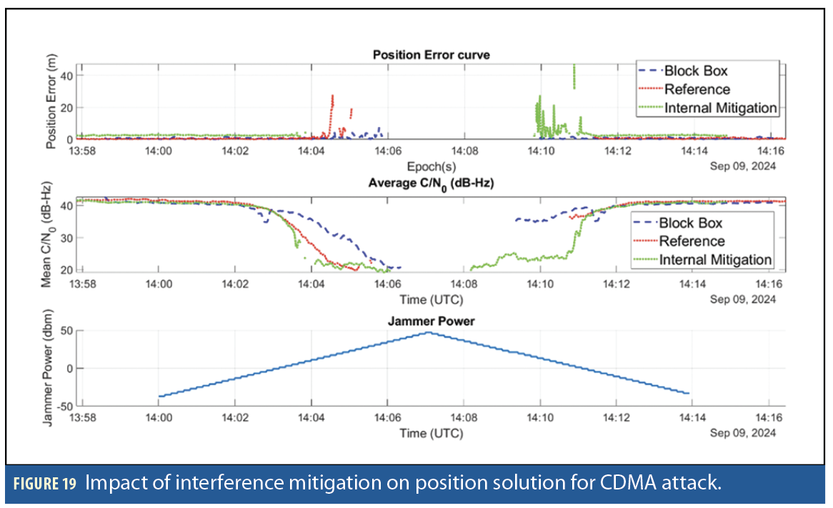
A CDMA type ramp-up ramp-down jammer superimposed on GNSS signals was replayed through Spirent. The jammer power was increased from -37 dBm with a step size of 2dBm to 47 dBm and back. The interference mitigation is performed in real-time using the developed system. The impact of interference mitigation in terms of extraction of position error and average C/N0 is illustrated in Figure 19.
Block-box based interference mitigation allows the receiver to track up to power levels of 31 dBm and restarts tracking at 13 dBm. The reference receiver with no interference mitigation can track up to 19 dBm and regain tracking at -3 dBm. The reference receiver with interference mitigation on state loses track around the 15 dBm jammer power level. It restarts tracking at the same time as the block-box based receiver but with a large position error.
Narrowband Interference
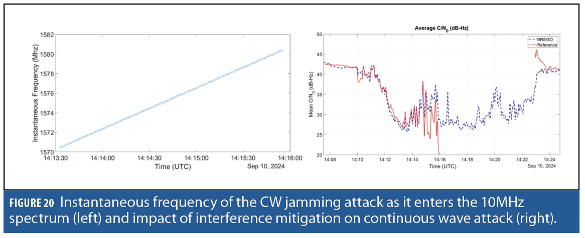
A jammer of power level 50W emitting a continuous wave that drifts from 1545 MHz to 1620 MHz in 15 minutes is added to a GNSS signal of a moving object. The instantaneous frequency of the jamming signal as it appears in the 10 MHz band is illustrated in Figure 20 (left). The developed system classifies the interference as periodic interference and detects it with the probability of detection equal to 0.99 with false alarm equal to 0.0023. The recorded signal is replayed through Spirent. The impact of interference mitigation in terms of the average C/N0 is shown in Figure 20 (right).
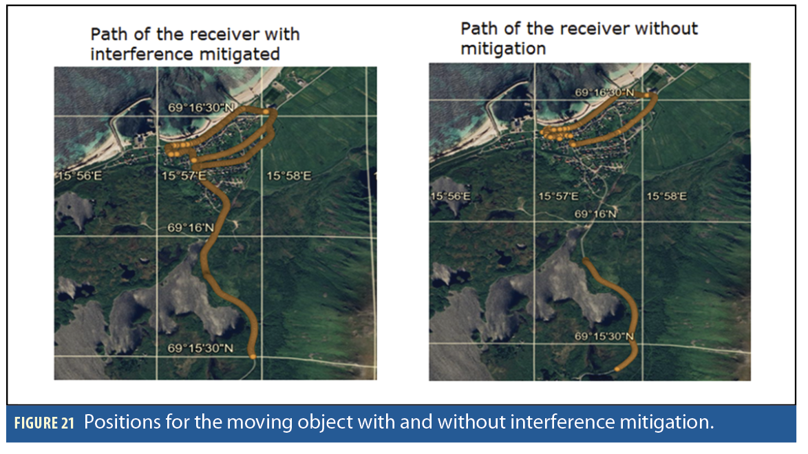
After 14:16, the block box achieves significant improvement over the reference receiver, as the reference receiver fails to estimate C/N0. The reference receiver’s performance deteriorates as the frequency of the interfering signal comes in the center of the L1 band. However, the GNSS receiver can effectively mitigate the interference and extract the position curve (Figure 21). Without interference mitigation, the complete path cannot be extracted.
Spoofing TEXBAT ds3 dataset
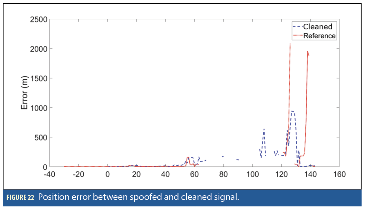
The spoofing mitigation experiments use the TEXBAT ds3 dataset [9], containing a spoofer with 1.3 dB higher power than the authentic signal. In this data set, a spoofer is injected from 120s and the spoofing starts approximately between 150 to 200s. This dataset contains spoofed GPS L1 signals, where a static receiver initially tracks an authentic signal before encountering a spoofer, resulting in a significant shift in the static location for approximately 50 seconds. Figure 22 shows the results of the spoofing mitigation by using the impulse method. The spoofing mitigation shows a reduction in static position error by up to 70% while also improving the duration of position availability.
Results from both jamming and spoofing mitigation evaluations demonstrate the potential benefits of the developed system in providing clean signals to a wide range of receiver types.
Conclusion and Future Work
We have demonstrated that the developed real-time and receiver-agnostic jamming and spoofing detection and mitigation system is effective on real-world data. Potential applications for the system include securing GNSS stations that require continuous, jamming- and spoofing-free GNSS signal recordings to provide publicly accessible data, as well as safeguarding receivers for critical assets. The system has been validated using a professional GNSS receiver and a software receiver (GNSS-SDR). The system is flexible and configurable and can be used with different radio frequency front-end and processing unit devices. A novel variant of the developed adaptive notch filter can track fast time-varying chirps because of an additional post-processing step and mitigates interferences without causing non-linear phase distortions by employing zero-phase filtering. The novel spoofer mitigation technique can remove the spoofer component from the TEXBAT ds3 signal. The developed system has certain limitations, including restricted computational speed due to CPU constraints, reduced effectiveness when mitigating interference from multiple equally powerful chirp jammers, and is dependent on the receiver’s ability to initially track authentic signals as well as on specific signal structures for successful mitigation.
Future work will focus on testing with more spoofing scenarios to improve current mitigation algorithms, integrating feedback from receivers and other sources for spoofing detection and mitigation in wider scenarios and implementing jamming and spoofing detection and mitigation on field programmable grid array (FPGA) for fast processing to create a compact, portable system suitable for a wider range of applications including dynamic environments and moving assets.
Acknowledgment
This work was funded by the European Space Agency (ESA) NAVISP program under the activity NAVISP-EL1-064: “Block-box for an optimized GNSS spectrum monitoring network using artificial intelligence.” We also acknowledge the support of ESA Technical Officer Luciano Musumeci for his contributions throughout the project. The views expressed can in no way be taken to reflect the official opinion of the ESA.
This article is based on material presented in a technical paper at ION GNSS+ 2025, available at ion.org/publications/order-publications.cfm.
References
(1) Misra, P, Enge, P., “Global Positioning System: Signals, Measurement and Performance,” 2nd Edition, 2006, Ganga-Jamuna Press: USA.
(2) Kaplan, E.D. and Hegarty, C., “Understanding GPS/GNSS: principles and applications,” 2017. Artech house.
(3) Dovis, F., “GNSS interference threats and countermeasures,” 2015, Artech House.
(4) Khan, Nabeel Ali, and Luis Enrique Aguado. “Adaptive Notch Filter based Interference Characterization and Mitigation for GNSS Receivers.” Proceedings of the 37th International Technical Meeting of the Satellite Division of The Institute of Navigation (ION GNSS+ 2024). 2024.
(5) Kormylo, J., & Jain, V., “Two-pass recursive digital filter with zero phase shift,” 1974 IEEE Transactions on Acoustics, Speech, and Signal Processing, 22(5), 384-387.
(6) Wesson, K.D., Shepard, D.P., Bhatti, J.A. and Humphreys, T.E., “An evaluation of the vestigial signal defense for civil GPS anti-spoofing.” In Proceedings of the 24th International Technical Meeting of the Satellite Division of the institute of navigation (ION GNSS 2011) (pp. 2646-2656) 2011, September.
(7) Goodfellow, I., Bengio, Y., Courville, A. and Bengio, Y., “Deep learning,” 2016, Cambridge: MIT press.
(8) Murphy, K.P., “Machine learning: a probabilistic perspective,” 2012. MIT press.
(9) Humphreys, T.E., Bhatti, J.A., Shepard, D. and Wesson, K., 2012. The Texas spoofing test battery: Toward a standard for evaluating GPS signal authentication techniques.
(10) Seco-Granados, G., Gómez-Casco, D., López-Salcedo, J.A. and Fernández-Hernández, I., “Detection of replay attacks to GNSS based on partial correlations and authentication data unpredictability,” 2021, Gps Solutions, 25(2), p.33.
(11) Khan, A.M., Iqbal, N., Khan, A.A., Khan, M.F. and Ahmad, A., “Detection of intermediate spoofing attack on global navigation satellite system receiver through slope-based metrics,” 2020, The Journal of Navigation, 73(5), pp.1052-1068.
(12) Negrinho, A., Boto, P., Fernandes, P., Mendonça, V., Nunes, F. and Sousa, F., “Signal Quality Monitoring Aspects in GNSS Signals Affected by Evil Waveforms,” In Proceedings of the 35th International Technical Meeting of the Satellite Division of The Institute of Navigation (ION GNSS+ 2022) (pp. 3947-3958), 2022, September.
Authors
Wahyudin P. Syam has worked on several ESA projects related to end-to-end GNSS transceivers at low frequency, GNSS spoofing, and machine learning for GNSS applications. His main roles at GMV are GNSS-related system development, software engineering and machine learning.
Nabeel Ali Khan develops digital signal processing algorithms for applications involving signal detection, instantaneous frequency estimation, jammer interference characterization and mitigation, design of time-frequency representation, and positioning using signals of opportunity.
Michael Turner is the lead engineer on several timing and navigation projects. He has published several papers on GNSS spoofing detection techniques and has two related patents in this area.
Luis Enrique Aguado is a Section Head in the Assured and Resilient PNT Division at GMV. With a Ph.D. in digital communication from the University of Manchester, UK, he has been active
in GNSS technology developmentsince 2002.
Ben Wales is a technical expert on GNSS systems and related technologies at GMV. With 20 years of experience in the PNT industry, he has been the architect and lead developer on numerous initiatives covering advanced PNT, snapshot positioning, PPP and signals of opportunity, amongst others.
Lisa Guerriero has a BSc in Automation Engineering from Polytechnic of Milan. With over a decade of experience in embedded systems, she specializes in custom firmware development and real-time GNSS solutions. Since 2019, she has contributed to advanced PNT systems at GMV, with expertise in SDR technologies.
Baris Toz has a MEng in Electronic and Communications Engineering from the University of Nottingham and hands-on experience in embedded systems, software development, and IoT technologies. He is skilled in low-level C programming, hardware-software optimization and system testing.
Inchara Lakshminarayan is a navigation engineer at GMV and works on projects for ESA, DSTL, RSSB etc. on topics such as sensor fusion, integrity, reliability and safety. She holds a double master’s degree and a Ph.D. from the University of Minnesota and has previously worked for the location tech team at Qualcomm, USA.
Tom Stacey has a BEng in Electrical and Electronic Engineering from Newcastle, UK, with a background in hardware design and digital signal processing. Since 2018, he has worked on several ESA projects and contributed to GNSS related systems hardware development.
Maria Ivanovici is a Senior Project Manager at GMV. She is responsible for managing a variety of navigation related projects, ranging from product development to service delivery.
Terri Richardson is the CANS-UK Section Head at GMV, where she works on several projects related to advanced GNSS positioning and integrity for user applications. She received a B.Sc. and M.Phil. in Surveying and Land Information from the University of the West Indies and a Ph.D. in Civil Engineering and Geodetic Science from The Ohio State University.
*EQUAL CONTRIBUTION