
In a GNSS spoofing attack, a terrestrial radio transmitter mimics GNSS signals at a greater signal strength than the actual system can transmit. In order to detect and mitigate a spoofing attack, it is important to know where a spoofing signal comes from and what it tries to accomplish for its ultimate neutralization.
A: A spoofing attack attempts to fool a GNSS receiver either by rebroadcasting genuine signals that are captured elsewhere or at a different time (a masking beacon or meaconing) or by broadcasting fake GNSS signals that are created to look like authentic GNSS signals (smart spoofing). A spoofer intends to mislead a GNSS receiver to use the spoofed signals as normal to produce a position fix at some place other than where it actually is (position-push) or to be where it is but at a different time (time-push) without knowing it.
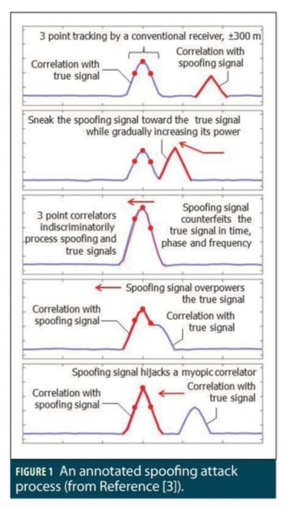
A successful single-channel spoofing attack implemented is annotated in Figure 1, where the blue peak is the correlation with the authentic signal, the red peak is the correlation with the spoofing signal, the red dots represent the early, prompt, and late correlators, and the red arrows indicate how the spoofing signal gets close to and then moves away from the authentic signal.
What does a spoofer need to know to be successful? The spoofer has to know the target receiver well in time, position, and frequency in order to get into its capture window. The receiver has to be indifferent, that is, assume that the received signals are clean without questions asked.
What Makes a GNSS Receiver Vulnerable to Spoofing?
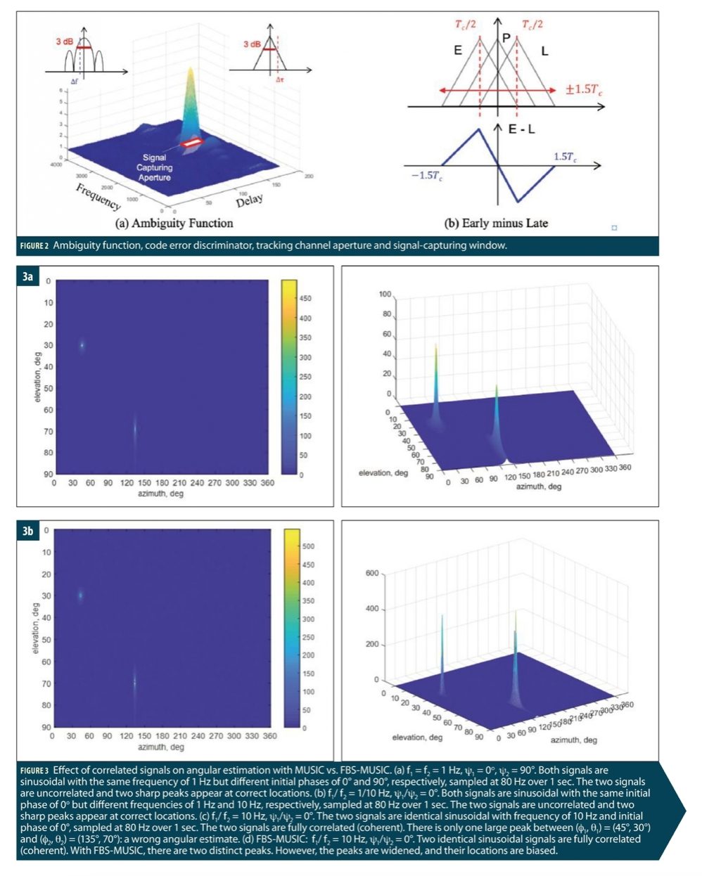
The vulnerability of a conventional GNSS receiver to spoofing stems from its design premise to track a single signal per satellite. Typically, a GNSS receiver uses three 1-ms long correlators in tracking having a 3 dB resolution of ±½ chips (150 m) in time and ±500 Hz in frequency. The code error discriminator in a delay lock loop (DLL) has a non-ideal responsiveness (not a Dirac delta function). Any signal that falls within a resolution cell, the capture window, as illustrated in Figure 2(a) can be “felt” by the receiver. As a result, the contribution to the total correlation values by a spoofing signal, just like multipath, biases the authentic signal estimates, leaving a door open to an encroaching spoofing signal.
Clearly, the early-prompt-late correlator architecture of a conventional GNSS receiver has a signal capturing window that is not narrow enough to reject any harmful signals. It is not wide enough, either, to spot any spurious signals that pop up over the horizon. In other words, this “myopic” architecture cannot “see” beyond ±1.5 chips as shown in Figure 2(b). Except for in the initial acquisition mode, it has no way to detect the presence of a spoofing signal until it is too late, that is, the bad influence has already been exerted. This “myopic” architecture is the root cause of vulnerability of conventional receivers to spoofing.
Spoofing Detection, Mitigation, and Tracking
There are many techniques for post-factual detection of spoofing along the signal processing chain. Notably is the chip transient analysis that can detect the distortion in chip shape caused by overlapped spoofing and authentic signals with a protection level of a fraction of chip at the 30-m level.
The presence of a spoofing signal cannot eradicate the existence of an authentic signal even though it may overpower it. If a spoofing signal always aligns itself to the authentic signal, no harm is done. When a spoofing signal captures a receiver and pulls away, two correlation peaks will emerge in the time-frequency domain. This observation has been used for spoofing detection.
The use of a larger surveillance space (panoramic) eliminates the potential risk of conventional myopic tracking loops, thus detecting the presence of spoofing signals before they become dangerous. The idea was the basis of the Auxiliary Peak Tracking (APT) method and the All Signal Acquisition Processing (ASAP) scheme. The latter goes one step further not only to mitigate the effect of spoofing on the authentic signal (electronic protection) but also to track the spoofing signals and use the spoofed solution for spoofing intent analysis (electronic support).
Spoofing Angular Estimation and Localization
The best way to mitigate spoofing is to prevent it from getting into the tracking and measurement generation processes of a GNSS receiver. From the time-domain waveforms, it is rather difficult to discern a spoofing signal from an authentic signal if they are off only slightly in time, frequency, or phase.
However, a spoofer cannot conceal its own physical presence. It has to counterfeit all satellites in view in order to push the position solution of a target receiver to the intended spoofed-to location. Yet, it is costly and even impractical for a spoofing system to place many transmitters around and above a target receiver to emulate a constellation. The spoofing signals are likely to be emanated from a limited number of directions.
A powerful way to discriminate against a spoofer is to exploit its spatial information, i.e., the angle of arrival (AOA). An antenna array can be used to steer a null in the direction of a spoofer so as to significantly reduce, if not completely eliminating, the influence of spoofing on authentic signals.
The AOA estimates to the spoofer used for spoofing detection and mitigation can be exploited advantageously for spoofer localization via triangulation from several distributed detectors or by one moving along a trajectory having a large angular extent over the spoofer. This provides an effective electronic support to ultimately neutralize the spoofer(s).
Correlated Spoofing: Forward and Backward Smoothing
Both GNSS authentic and spoofing signals are below the noise, which are “picked up” from the noise first by despreading correlation. An obvious benefit of such a post-correlation approach is its ability to exploit AOAs to differentiate the authentic signal from spoofing signal even when their energy peaks coincide in the delay-Doppler domain.
Instead of having a code and carrier tracking loop for each array element, the master-slave architecture only implements one tracking loop for a reference antenna (the master channel), and the code and carrier replicas from the master channel are used to drive the remaining antennas (the salve channels) so as to maintain the coherence across the array. The complex correlators contain the spatial information about both the authentic and spoofing signals that are used for angular estimation. A spoofing signal is mitigated by generating a null in its direction while preserving the authentic signal in the main beam, thus closing the tracking loop for the master channel.
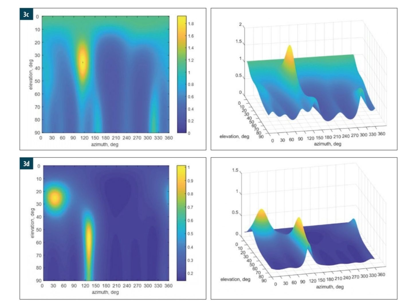
The multiple signal classification (MUSIC) algorithm is widely used for high-resolution angular estimation with an antenna array and has been applied for spoofing detection and mitigation. However, there is a technical complexity in that the MUSIC algorithm does not perform well with correlated signals, which is the case when a spoofing signal gets close to an authentic signal in time, frequency, and phase. A popular method to address this problem is to decorrelate the signals via forward and backward smoothing (FBS). Intuitively, two identical sinewaves are coherent. If they are off in phase by 90 degrees, their cross-correlation is zero and the two coherent signals are effectively de-correlated.
To illustrate the effect, consider the following example with a seven-element controlled reception pattern antenna (CRPA) receiving two signals from the two directions with azimuth and elevation (φ1, θ1) = (45°, 30°) and (φ2, θ2) = (135°, 70°), respectively, and both with SNR = 10 dB. The angular search spacing is 0.5° from 0° to 90° for elevation and 0° to 360° for azimuth.
Figure 3 shows the image (left) and surface (right) of the pseudospectrum of MUSIC or FBS-MUSIC where the peak location provides an angular estimate for uncorrelated signals (a-b) and correlated signals (c-d).
Correlated Spoofing: Nullspace Projection
An alternative way to deal with two correlated signals is to separate them via projection to each other’s null space. Assume that the array output x(t) contains two signals sa(t) and sb(t) in directions a and b, respectively, buried in noise n(t) as:

By projecting x(t) onto the nullspace of sa(t) in direction a via the orthogonal projection matrix P⊥a= I – aaH/(aHa) such that P⊥a a = 0, we obtain the projected signal as:

which removes a yet retains b. Similar operation can be carried out by projecting x(t) onto the nullspace of sb(t) in direction b via P⊥b = I – bbH/(bHb) (P⊥b b = 0) as:

In this way, the two signals in x(t) are spatially separated into za(t) and zb(t) without the influence of one on the other. We can then estimate the directions a and b and track the signals sa(t) and sb(t), respectively.
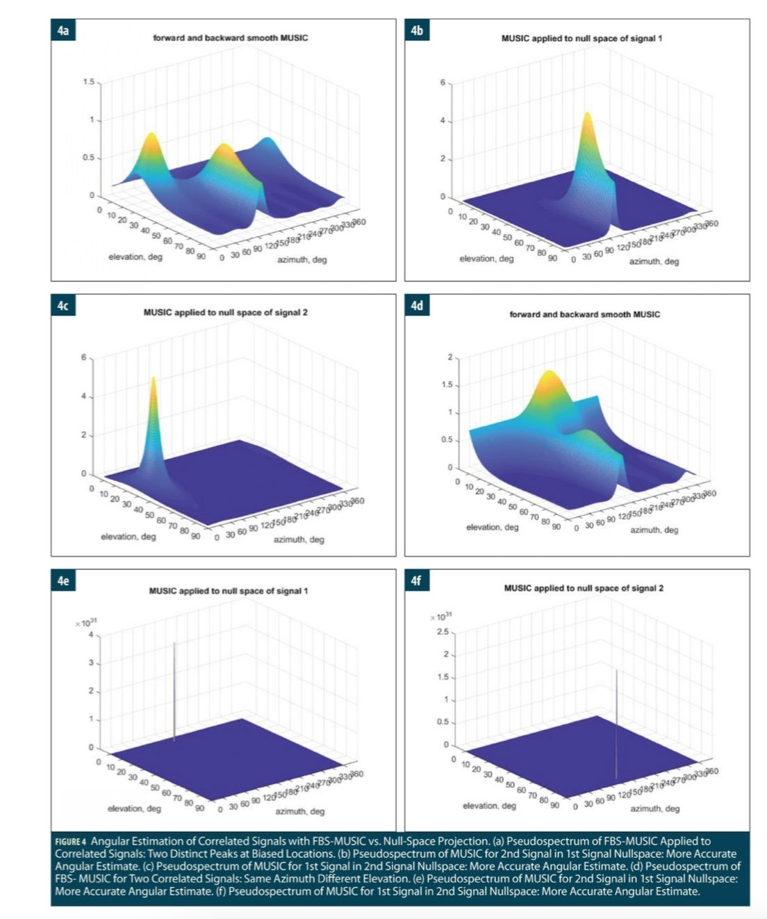
Consider the same example with two identical complex signals at (φ1, θ1)= (45o, 30o) and (φ2, θ2) = (135°, 70°), respectively, with lower SNR = 4.8 dB. Figure 4(a) shows the image and surface plots of the pseudospectrum of FBS-MUSIC. The FBS-MUSIC detects the two correlated signals, but their angular estimates are biased as (φ1, θ1) = (32.00°, 25.50°) and (φ2, θ2) = (133.50°, 64.50°).
Figure 4(b) shows the image and surface plots of the pseudospectrum of MUSIC applied in the nullspace of the first signal whose direction is known with an offset of 1o. After the projection nullifies the first signal, the second signal is detected with a more accurate angular estimate as (φ2, θ2) = (133.00°, 74.00°).
Similarly, Figure 4(c) shows the pseudospectrum of MUSIC applied in the nullspace of the second signal using the direction estimate (φ2, θ2) from the previous step. After the projection nullifies the second signal, MUSIC detects the first signal again with a more accurate angular estimate as (φ1, θ1) = (43.00°, 30.50°).
As shown in Figs. 3(d) and 4(a), FBS-MUSIC can work with correlated signals but may produce biased angular estimates. To further investigate, again consider two identical sinewaves with SNR = 6 dB, which have different elevations of 5° and 75° but the same azimuth of 155°.
Figure 4(d) shows the pseudospectrum of FBS-MUSIC, which has a dominant peak and a second elongated peak at (azimuth, elevation) = (194o, 9o) and (154o, 64o), respectively. Clearly, the angular estimates are biased.
Alternatively, we can project the array output to the nullspace of the first signal and then estimate the second signal and vice versa. An angular error of 1o is added to construct the nullspace projection matrix at (156°, 6°). The resulting pseudospectrum of MUSIC is shown in Figure 4(e), which leads to a more accurate angular estimate of (156°, 78°).
Similarly, construct another nullspace projection matrix at the angular estimate of (156°, 78°) of the second signal and then estimate the first signal. The resulting pseudospectrum of MUSIC is shown in Figure 4(f), which leads to an angular estimate of (150°, 6°). Clearly, the angular biases are largely removed.
Spoofing Signal Tracking and Angular Estimation for Localization
In GNSS applications, we start with no spoofing so a GNSS receiver can obtain good AOA estimates of authentic signals in view. The AOA of each authentic signal is used to form a beam toward the GNSS satellite for tracking in a master-slave architecture on one hand, and to construct a projection matrix with a null toward the satellite on the other hand. In the satellite’s nullspace, spoofing can be detected if present and its AOA is estimated, as illustrated in Figure 5.
In parallel, the AOA estimate of spoofing is used to steer a null toward the spoofer for tracking in the master channel on one hand, and to construct the projection matrix onto the nullspace of the spoofer for authentic signal tracking and AOA estimation on the other hand.
In this way, the spoofing signal is prevented from getting into the master tracking channel but left intact at the master-slave correlator outputs for its angular estimation and localization via triangulation. A tracking loop similar to that for the authentic signal in Figure 5 can be configured to track the spoofing signal and obtain a spoofed navigation solution for spoofing intent analysis.

Authors

Chun Yang is Chun Yang received his title of Docteur en Science from the Université Paris-Saclay (previously known as Université de Paris XI). After postdoctoral research at the University of Connecticut, he has been working on adaptive array, synthetic aperture, and baseband signal processing for GNSS, radar, and communications signals and systems; nonlinear state estimation in target tracking, integrated inertial and distributed collaborative navigation; and optimization in resource management and information fusion. Dr. Yang is the recipient of 2007 ION Samuel M. Burka Award and the winner of 2009 IEEE NAECON Grand Challenge.

Andrey Soloviev is a principal at QuNav. His research and development interests focus on sensor-fusion and signal-processing implementations for GNSS-degraded and GNSS-denied applications. He holds a Ph.D. in electrical engineering from Ohio University. He is a recipient of the Institute of Navigation (ION) Early Achievement Award and the RTCA William Jackson Award.


