The advanced navigation architecture explored combines multi-sensor fusion and resilient PVT techniques.
GIUSEPPE TOMASICCHIO, LUCA ANDOLFI, MARCO BRANCATI, ARSENIO MARIA DI DONNA, SIMONE GIANNATTASIO, TELESPAZIO S.P.A. ROBERTO DEL PRETE, LUCA OSTROGOVICH, ALFREDO RENGA, MICHELE GRASSI, UNIVERSITY OF NAPLES FEDERICO II MICHELE CERESOLI, STEFANO SILVESTRINI, MICHÈLE LAVAGNA, POLITECNICO DI MILANO
Moon exploration has emerged as a significant frontier in the era of space commercialization in recent years, with many public and private entities showing growing interest and investment in lunar missions. This increase in lunar and cislunar activities has prompted outstanding initiatives promoted by NASA and the European Space Agency (ESA). Historically, lunar missions have relied on deep-space Earth ground-segment infrastructures to obtain accurate knowledge of the spacecraft trajectory, but today, many studies are being conducted to demonstrate improvements in user position, velocity and timing (PVT) estimation enabled by a navigation constellation around the Moon.
The objective of this study is to describe an approach that uses sensor-fusion techniques based on a tightly-coupled Extended Kalman Filter (EKF) to integrate lunar GNSS-like one-way
ranging (OWR) signals with a wide range of on-board observables, such as inertial measurement units (IMU), altimeters, two-way ranging (TWR) with an orbiter in Elliptical Lunar Frozen Orbit (ELFO) and visual-based navigation (VBN) techniques for estimating both the spacecraft state and the receiver clock bias and drift, in different phases of a lunar landing at the Shackleton Rim. The VBN algorithms applied are based on seleno-referenced, high-fidelity lunar images (from 30m/px to 5m/px) generated through the Visual Scenario Generator (VSG) module that’s integrated in the Interactive Mission Modeling, Visualization/Validation (IMMV2) tool, developed in the Telespazio Concurrent and Collaborative Design Facility (C2DF). IMMV² implements various functionalities in a digital twin for mission digitalization (MDT), end-to-end testing and validation. Finally, a preliminary measurement outlier rejection strategy was implemented in the loop, as the recent lunar lander missions have demonstrated the importance of identifying and rejecting incorrect measurements that could cause mission failure.
The Era of Future Lunar Exploration Missions
The growing number of initiatives promoted by NASA, ESA and other space agencies underline a concerted effort to expand our understanding and resource use of the lunar environment. One of the principal objectives is to realize a lunar communication and navigation constellation around our natural satellite to support future robotic and human exploration missions, such as Artemis [1] and Argonaut [2]. These services also will support the birth and development of the future “Lunar Economy” in terms of space tourism and, for example, the possibility of using lunar resources on site, which makes exploring other planets in the solar system cheaper and easier.
Guaranteeing accurate position performance is a pillar of such initiatives. The challenge today is to exploit a navigation constellation to improve navigation accuracy performance. Because only a few navigation satellites will be available in the cislunar environment in a first phase, it is fundamental to demonstrate the integration of these observables with other sensors’ measurements, such as IMUs, altimeters, TWR measurements and VBN (Figure 1).
The navigation constellation considered is composed of four spacecraft placed on four ELFOs with a 24-hour orbital period. The selection of orbital parameters was optimized to guarantee good navigation geometrical performance on the South Pole, the primary target for future lunar missions.

Mission Scenario: Landing on lunar South Pole
The study considers a landing trajectory that starts from about -75° latitude, covering a total angle of around 30° and lasting about 22 minutes. The trajectory profile was generated following the guidelines of the reference trajectory of the ESA’s Argonaut lander [2] starting from a LLO and reaching a high gate arrival (HGA), proceeding with an almost vertical descent toward low gate arrival (LGA) and then until touchdown on the Shackleton Rim (Figure 2).
The following assumptions/choices were made:
• An initial LLO at an altitude of about 15 km until the beginning of the first descent maneuver toward the HGA.
• An HGA at an altitude of about 2 km and a LGA at approximately 150 m in the International Celestial Reference Frame (ICRF).
The trajectory segment from the HGA to touchdown was divided into three segments, with the lander performing a finite maneuver at different thrust levels to simulate modulation of the engine during the terminal descent phase in each. For both the ballistic and maneuvered segments, the following forces were considered to propagate the dynamics:
• Gravitational force exerted by the main body, calculated using the LP150Q lunar gravity model, which considers spherical harmonics. up to degree and order 150.
• Third-body effect generated by the Earth and the Sun.
• Solar Radiation Pressure (SRP), calculated with a solar luminosity of 3.828e+26 W, a lander area of 20 m2 and a coefficient of reflectivity, Cr, equal to 1.
In the maneuvered segments, a constant thrust level of 11.622 kN was considered until reaching the HGA, followed by three finite maneuvers with thrust levels of 2.851 kN, 2.786 kN, and 2.704 kN, respectively. A specific impulse of 300 s was considered for the calculation of consumed fuel. The lander has an initial wet mass of 2,500 kg and a dry mass of 1,200 kg.
Shackleton Rim was selected for the landing site based on studies of its average annual exposure to solar illumination providing the most plausible location for lunar landing. It’s also one of the most promising landing sites identified by NASA for the future Artemis missions [3].

Synthetic Data Generation Through the IMMV2 Tool
The IMMV2 tool has been developed within the Telespazio Research and Innovation Laboratories (R&I Labs) [4, 5] and provides a co-simulation realistic virtual environment for mission digitalization, 3D modeling and end-to-end (E2E) testing and validation, known as mission digital twin (MDT). The tool harnesses state-of-the-art technologies, using the unreal engine (UE) platform for realistic rendering, synthetic data generation and virtual reality (VR) interactivity to provide a complete fault analysis, detection and exclusion mechanism for system robustness analysis through an advanced sensor fusion of multiple synthetic data. MDT is fundamental in an era when complex space-based missions demand high safety margins and low risk levels and where it is becoming imperative to foresee all possible unexpected system behaviors that could lead to mission failure.
For this work, the visual scenario generator (VSG) module generated the fully synthetic images and altimetry used for the VBN algorithm and altimetric information. By merging VSG capabilities and a bilateral real-time co-simulation that exploits the user datagram protocol (UDP), named Ping-Pong, between the UE5 and a backend simulation environment, it is possible to import time-defined custom trajectories and attitudes powered by a specific space dynamic propagator build up in the backend environment (e.g. for the lander dynamics simulation). As a result, VSG allows the extraction of georeferenced optical/LiDAR images and other synthetic observables in different conditions. This is crucial to generate vast, fully synthetic datasets to train AI-powered technologies (e.g. VBN) or build up high fidelity mission DT.
The lunar DEM was generated using topographic data collected by the Lunar Reconnaissance Orbiter (LRO) Lunar Orbiter Laser Altimeter (LOLA). Using integrated maps at different resolutions (30m/px to 5m/px), the process generated high fidelity meshes of the lunar region of interest [6]. VSG functionalities are summarized in Figure 3.

Multi-Sensor Fusion Functional Architecture
• The proposed multi-sensor fusion navigation architecture is shown in Figure 4. The part of the scheme reported in the upper part and highlighted with a blue rectangle represents a simplified view of the VBN block. The lower part highlights the other sensors and observables that feed the navigation filter (yellow block) to obtain the estimation of both the spacecraft state and the receiver clock bias and drift (green block).
• The VBN is integrated in the existing navigation architecture with the navigation constellation observables and additional sensor measurements to provide an accurate estimate of the lander position along all the different phases of its trajectory.
• The methods of integrating GNSS-like signals with inertial navigation system (INS) estimates and information from other sensors can be classified in two main approaches: loosely coupled and tightly coupled. In this work, the limited number of navigation satellites makes it unlikely for the first approach to provide a PVT estimate. A tightly coupled integration scheme was chosen as the optimal method to incorporate satellite measurements with the remaining sensors (Figure 4).

VBN, Absolute Module
The VBN module [7, 8] uses topographical markers, specifically craters, and correlates them with an extensive catalogue [9] to achieve high-precision navigation. This module demonstrates robust resilience against errors in initial position estimation, due to its reliance on globally identifiable features. Its absolute working mode operates independently of prior image data or positional history, enabling effective navigation even in “lost-in-space” scenarios. The module operates in three main stages: detection, matching and pose estimation. Initially, high-resolution imagery from the spacecraft is input to a deep learning (DL) based crater detector [10]. Identified craters are matched to a database of known craters using a matching strategy. Finally, the VBN module proceeds to pose estimation, where the transformation from two-dimensional to three-dimensional correspondences is managed by solving a Perspective-n-Point (PnP) problem [11]. Figure 5 illustrates the VBN module architecture [8].

VBN, Relative Mode
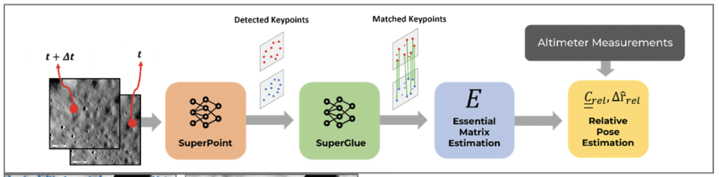
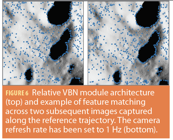
In the final phases of descent, as the spacecraft decreases its altitude, the number of craters visible to the camera diminishes significantly. Furthermore, many of the detected craters are too small to be matched with most existing catalogues [9]. This issue is mitigated at higher altitudes, where the visible craters are more numerous and larger, and are therefore surveyed in many available crater catalogues. To address this challenge, as the altitude decreases above around 15 km, the proposed algorithm bypasses crater detection and matching, instead focusing on identifying and tracking common surface features, such as rocks and rilles, in a sequence of overlapping image pairs captured along the trajectory. By tracking these features from frame to frame, the algorithm estimates the camera’s pose relative to its previous position. The module unfolds across three main stages: first, a fully convolutional neural network, Superpoint, [12] is tasked to detect keypoints in two subsequent frames. Subsequently, an attentional Graph Neural Network (GNN), SuperGlue [13], leverages the attentional mechanism of the transformer architecture [14] to efficiently and reliably match corresponding keypoints across the image pair. By exploiting the resulting epipolar geometry, the relative pose between the two viewpoints can be retrieved (Figure 6, bottom). Altimeter measurements are integrated in the pose estimation pipeline to resolve the scale ambiguity. Relative VBN module architecture is represented in Figure 6, top [8].
Navigation Measures: On-Board Sensors and NAVSATs Observables
Altimeter
When used in conjunction with a navigation constellations’ one-way measurements, altimeters can directly determine the vertical position within a user-centered East-North-Up (ENU) reference frame. In this study, the altimetric measures have been extracted by the synthetic environment reconstructed with the IMMV2 tool. Because the tool provides both ideal and altered measurements, the altimeter readings have been post-processed by introducing additive Gaussian white noise to the vertical component of the spacecraft. To simulate the behavior of contemporary laser altimeter technology, the noise’s standard deviation is adjusted proportionally to 1% of the actual user height [1,15].
IMU
An accelerometer measures the non-gravitational acceleration experienced by the spacecraft. In this case, the accelerometer is key to capturing the thrust maneuvers accelerations. A comprehensive accelerometer model typically includes errors such as misalignment, cross-axis sensitivity, sensor biases, and scale factor errors. However, for this study, the model has been simplified by combining all these errors into additive Gaussian white noise. Although this model may underestimate the impact of those errors in the initial coasting phase, during the thrusting phase the acceleration provided by the thrusters is orders of magnitude greater than the neglected biases. The noise’s standard deviation is representative of commercial high-fidelity accelerometers. This simplification allows for decoupling the orbital estimation problem from the attitude estimation problem, as the accelerometer readings are assumed to be already expressed in the inertial reference frame (specifically, the ICRF) used for propagating spacecraft dynamics.
Navigation Satellites Observables
The one-way measurements obtained from the j-th navigation servicer are determined using the pseudorange and pseudorange-rate
. The pseudorange is calculated using conventional time-of-arrival (TOA) techniques (Equation 1):

The pseudorange
is determined based on the geometric range, where c represents the speed of light. It is computed by considering the system time Tu at which the signal would have reached the user in the absence of errors, the receiver clock bias δtu, the system time Tj at which the signal left the servicer, the offset of the servicer clock from the system time δtj, and the noise

introduced by various sources of errors including interference effects, receiver noise, instrumental delays, multipath losses, and relativistic effects. On the other hand, the pseudorange-rate is obtained from Doppler frequency measurements. It is calculated by taking the difference between the nominal carrier frequency and the received signal frequency (Equation 2):
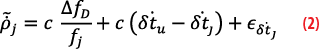
where the terms and
represent the errors associated with the clock drift of the receiver and servicer, respectively. The term
encompasses the remaining noises. To simplify the pseudorange and pseudorange-rate equations, all the error contributions can be combined into single terms as in Equations 3 and 4:


where bc and dc denote the receiver clock bias and drift, respectively, measured in meters and meters per second. These two terms are modeled using a two-state clock model [16]. The frequency deviation, which corresponds to the clock drift, arises from two types of noise: White Frequency Modulation (WFM) and Random Walk Frequency Modulation (RWFM). The resulting clock bias is represented as a combination of Wiener noise and integrated Wiener noise. The dynamical system that simulates the evolution of these quantities is summarized in Equations 5 and 6. The terms and
represent Gaussian white noises. Their standard deviation can be adjusted accordingly to match the Allan variance of the specific type of receiver clock desired for the simulation.


Within the navigation filter, the prediction of pseudorange and pseudorange-rate involves using the information transmitted through the navigation message. This information is used to calculate the position and velocity of the navigation constellation satellites, as well as the corrections needed to synchronize the servicer clocks with the system time. For Galileo and GPS, the broadcast ephemerides are provided in the form of 16 quasi-Keplerian parameters, which enable the computation of the GNSS satellite states in the Earth-Centered Earth-Fixed (ECEF) frame [17]. The specific structure and update frequency of the broadcast navigation message are yet to be determined. Consequently, the residual errors in the predictions arising from the orbit determination and time synchronization (ODTS) process conducted on the ground, referred to as signal in space error (SISE), are modelled as simple additive Gaussian white noises. It is assumed that the retrieved states of the navigation constellation satellites are expressed in the ICRF frame, as a proper definition of an official Moon-Centred Moon-Fixed (MCMF) frame is still not available.
Two-Way Ranging with an Additional Satellite in ELFOAnother source of observables investigated in this study derived from TWR measurements involving an additional ELFO orbiter in a 12-hour orbital period. Unlike OWR, TWR measurements provide range and range-rate between the two spacecrafts that remain unaffected by receiver clock offset, thus offering a more reliable measure compared to standard OWR observables. In this simulation, a simplified TWR measurement model, which does not include remanent biases due to uncalibrated group delays, is implemented. Specifically, the range and range-rate quantities are computed according to Equations 3 and 4 but without the contribution of the clock bias and drift. Although this simplification might lead to an underestimation of the actual errors, it provides an initial reference to improve in future studies. The resulting measurements are forwarded to the EKF and treated similarly to the OWR pseudorange and pseudorange-rate. Navigation Filter The navigation algorithm used in this research is based on an EKF, which estimates the user’s inertial position and velocity, as well as the receiver clock and drift. To achieve precise estimation of orbital states, a specialized orbital dynamical model is implemented, considering the limited availability of observables. A balance between model accuracy and computational efficiency is achieved through a compromise. The model includes gravitational accelerations from the Moon’s central gravity, the J2 effect, and Earth’s third-body perturbation. It is assumed that dedicated look-up tables or Chebyshev polynomial coefficients can be stored on-board or periodically updated to compute Earth’s position at the current epoch. Additionally, measurements from the IMU are used to account for non-gravitational accelerations, such as thrusting maneuvers. The position and velocity components of the state are discretely integrated using an explicit Runge-Kutta (RK) integration scheme. Balancing integration order with computational demands reveals that, for a navigation filter running at 1 Hz, a simple two-stage Heun method reduces propagation times by half while maintaining negligible accuracy loss compared to higher-order RK methods. Conversely, the clock states are integrated using a simple Euler model. The remaining filtering steps follow traditional EKF implementations, with the exception of using the Joseph covariance correction formulation to ensure the covariance matrix remains positive definite. The Mahalanobis distance check method is implemented to reject any outliers in the measurements, ensuring good robustness against possible sensor faults [18].

Results
CASE 1:
Absolute VBN Algorithm PerformanceThe performance evaluation of the absolute pose estimation algorithm is showcased using a series of uniformly spaced images captured along the initial segment of the landing trajectory, from 17 to about 14 km of altitude. Each image was processed by the absolute pose estimation algorithm, which involved detecting craters, matching them with the onboard catalogue, and retrieving the pose by solving the corresponding PnP problem. The camera’s boresight axis was assumed to point in the nadir direction for the entire descent phase. Table 2 reports camera specifications. To optimize the number of detected craters, the Sun elevation angle was maintained at 14 throughout the image sequence reported in [6]. Figure 7 depicts an example of detected and matched craters over a portion of the lunar surface overflown by the lander.Figure 8 illustrates the trend of the total error and its components, both horizontal and vertical, alongside the number of detected and matched craters. The selected lunar region serves as an excellent test case for the algorithm, featuring a diverse array of craters in terms of size, density and distribution. At the beginning of the trajectory segment, the lander overflies an area with a scarce distribution of craters, resulting in increased error. For approximately 10 seconds, the number of matched craters is insufficient to solve the associated EPnP problem [11]. Throughout the trajectory, an increase in the number of detected and matched craters corresponds to a general decrease in the error level. An equal number of matched craters does not always yield the same error level. This discrepancy is due to the presence of mismatched craters and varying crater arrangements within the images. In the final segment of the trajectory, the reduced altitude no longer allows for a sufficient number of craters to be detected or matched with the onboard database. Consequently, it becomes necessary to transition to a relative VBN algorithm. The absolute VBN pipeline has yielded an average position error of 270.14 m, with a horizontal component of 216.11 m and a vertical component of 54.028 m.

CASE 2:
Relative VBN Algorithm PerformanceThe relative displacement and rotation errors with respect to the ground were the performance parameters considered. The proposed algorithm was applied to a sequence of images captured along a portion of the reference trajectory, ranging from 14 km to 2 km of altitude, immediately following the absolute mode of the VBN module. Both instantaneous and mean relative displacement errors along the trajectory were computed. Throughout the testing procedures, the same camera specifications reported in Table 2 were adopted. Figure 9 shows the time evolution of the error in the relative displacement estimate, with its horizontal and vertical components, along the trajectory segment of interest. The mean error is approximately 25 m, with horizontal and vertical components of 22.39 m and 5.83 m, respectively.
CASE 3:
VBN/IMU/Altimeter + 1 Navigation Satellite Figure 10 (top) displays navigation performance when the VBN measurements are integrated within a navigation filter that further leverages IMU and altimeter readings. A summary of the adopted simulation parameters and sensor settings is reported in Table 1. In the initial part, the filter struggles to reach convergence because the altimeter readings alone are unable to provide complete observability of the state. However, as soon as the absolute VBN position measurement becomes available, the error suddenly drops to a few hundreds of meters. As the lander continues along its descent trajectory, the absolute VBN cannot provide any more information, thus the filter starts using estimated velocity measurements. Throughout this phase, the velocity error stabilizes while the position error exhibits a linear drift in time. Simulations have shown using the relative VBN measurement can reduce the final navigation error up to 1 km with respect to the scenario in which only the absolute measurements are leveraged. Finally, once all the VBN measurements become unavailable, the position error keeps increasing because, like the initial few minutes, the filter does not have enough observables to properly determine the lander state.

CASE 4:
VBN/IMU/Altimeter + 4 Navigation SatellitesTo improve navigation accuracy, Figure 10 (center) reports the position error when the previous architecture is further enhanced with one-way measurements from a navigation constellation. Four navigation satellites are visible throughout the landing trajectory. Because of the optimal constellation geometry, once the filter has reached convergence, the navigation error is extremely small. The only exception happens at about 4 minutes, when a peak error of about 80 m is reached. However, such sudden performance drop is caused by the large thrust maneuvers performed to target the desired landing site.
CASE 5:
VBN/IMU/Altimeter + 1 Navigation Satellite + TWRThe navigation constellation visibility pattern gradually shifts throughout the day as the navigation satellites move toward the periselene of their 24-hour orbits. Depending on when the initial landing burn is executed, a different number of navigation signals might be available. For this reason, Figure 10 (bottom) investigates the scenario in which only a single one-way navigation signal is captured by the on-board receiver. However, at the same time, an additional and more accurate observable with respect to the OWR signals is obtained by performing TWR with a satellite in a 12-hour period ELFO. With this configuration, the overall position error never exceeds 200 m. However, it is important to stress that the actual error strongly depends on the relative geometry of the satellites with which OWR and TWR are performed. If they are closely aligned, the information provided by the two will not allow an accurate reconstruction of the trajectory due to the much higher dilution of precision. Additionally, after 9 minutes, i.e., when the VBN measurements cease to be available, the position error gradually increases because a single OWR satellite, together with the TWR and altimeter readings, are not enough to provide complete observability of the state. With this in mind, the benefits of having a VBN solution are clearly evident during the first minutes of the landing, where the position error is consistently kept below 100 m. Conclusions and Future Works In this article, an advanced navigation architecture based on multi-sensor fusion, with the integration of different measurements and VBN module, has been presented showing the application of the IMMV2 tool, developed in the Telespazio R&I Labs. The IMMV2 simulations highlighted that a proper integration of OWR signals provided by a lunar navigation constellation, inertial sensors and VBN can guarantee good navigation performance for a landing user. In particular, a combination of VBN/IMU/altimeter and four navigation satellites can guarantee a position error in the order of tens of meters. If only one satellite is present, a combination of OWR, VBN, IMU and altimeter can guarantee good navigation performance below 100 m until the absolute VBN provides measurements.

As soon as relative navigation is introduced, the position error increases remaining below 1 km. If this last configuration is integrated with a TWR observable provided by an ELFO orbiter in an optimal relative geometrical configuration with respect to the navigation satellite, the position error can be mitigated and lowered below 200 m. The VBN complete pipeline for both absolute and relative mode were also presented, and demonstrate an average position error of 270.14 m, with a horizontal component of 216.11 m and a vertical component of 54.028 m in the case of absolute VBN and 25 m, with horizontal and vertical components of 22.39 m and 5.83 m in case of relative VBN.Finally, a preliminary measurement outlier rejection strategy was implemented to ensure good robustness against possible sensor faults that could cause a lunar landing mission failure. Future works will focus on extending the lunar surface area to test sensor fusion in other scenarios, such as: orbiting users and/or surface rovers; augmenting the synthetic image dataset; testing the effects of varying illumination conditions on the VBN algorithm; improving the navigation filter for the final landing phase; creating a mixed reality framework where the IMMV2 validates algorithm performance and real-time capabilities together with a Processor-in-the-loop (PIL) test setup; and implementing FDE techniques to improve the user mission resilience.


Acknowledgements
This article is based on material presented in a technical paper at ION GNSS+ 2024, available at http://ion.org/publications/order-publications.cfm
References
References
(1) Artemis, https://www.nasa.gov/humans-in-space/artemis/.
(2) “Argonaut,” https://www.esa.int/Science_Exploration/Human_and_Robotic_Exploration/Exploration/Argonaut.
(3) “NASA Identifies Candidate Regions for Landing Next Americans on Moon.”, https://www.nasa.gov/press-release/nasa-identifies-candidate-regions-for-landing-next-americans-on-moon/.
(4) G. Tomasicchio, M. Brancati, A. Ceccarelli, A. De Matteis, L. Spazzacampagna, “An Integrated Concurrent & Collaborative Design and Verification approach for the Telespazio Research & Innovation Laboratories”, POLARIS Innovation Journal, n. 45/2021.
(5) G. Tomasicchio, A. Ceccarelli, A. De Matteis, L. Spazzacampagna, “A Concurrent and Collaborative Design Facility for End to End space mission modelling and design: an integrated approach from mission requirements to satellite operations and service delivery engineering.”, SECESA 2020, ESA/ESTEC.
(6) G. Tomasicchio, L. Andolfi, M. Brancati, A.M. Di Donna, S. Giannattasio, R. Del Prete, L. Ostrogovich, A. Renga, M. Grassi, M. Ceresoli, M. Lavagna, “Multi-Sensor Fusion for Improved Navigation in Lunar Landing Missions”, ION 2023.
(7) Del Prete, R., & Renga, A. (2022). A Novel Visual-Based Terrain Relative Navigation System for Planetary Applications Based on Mask R-CNN and Projective Invariants. Aerotecnica Missili & Spazio, 101(4), 335–349. https://doi.org/10.1007/s42496-022-00139-0.
(8) Ostrogovich, L., Del Prete, R., Tomasicchio, G., Longepe, N., & Renga, A. (2024). A Dual-Mode Approach for Vision-Based Navigation in a Lunar Landing Scenario. In Proceedings of the IEEE/CVF Conference on Computer Vision and Pattern Recognition (pp. 6799-6808).
(9) Robbins, S. J. (2019). A New Global Database of Lunar Impact Craters >1–2 km: 1. Crater Locations and Sizes, Comparisons With Published Databases, and Global Analysis. Journal of Geophysical Research: Planets, 124(4), 871–892. https://doi.org/10.1029/2018JE005592.
(10) Del Prete, R., Saveriano, A., & Renga, A. (2022). A Deep Learning-based Crater Detector for Autonomous Vision-Based Spacecraft Navigation. 2022 IEEE 9th International Workshop on Metrology for AeroSpace (MetroAeroSpace), 231–236. https://doi.org/10.1109/MetroAeroSpace54187.2022.9855951.
(11) Li, S., Xu, C., & Xie, M. (2012). A Robust O(n) Solution to the Perspective-n-Point Problem. IEEE Transactions on Pattern Analysis and Machine Intelligence, 34(7), 1444–1450. https://doi.org/10.1109/TPAMI.2012.41.
(12) D. DeTone, T. Malisiewicz, and A. Rabinovich, “SuperPoint: Self-Supervised Interest Point Detection and Description,” in Proceedings of the IEEE Conference on Computer Vision and Pattern Recognition (CVPR) Workshops, Jun. 2018.
(13) P.-E. Sarlin, D. DeTone, T. Malisiewicz, and A. Rabinovich, “Superglue: Learning feature matching with graph neural networks,” in Proceedings of the IEEE/CVF conference on computer vision and pattern recognition, 2020, pp. 4938–4947.
(14) A. Vaswani et al., “Attention Is All You Need,” Jun. 2017.
(15) S. Silvestrini, M. Piccinin, G. Zanotti, A. Brandonisio, P. Lunghi, and M. Lavagna, “Implicit extended kalman filter for optical terrain relative navigation using delayed measurements,” Aerospace, vol. 9, no. 9, p. 503, 2022.
(16) L. Galleani, “A tutorial on the two-state model of the atomic clock noise,” Metrologia, vol. 45, no. 6, S175, 2008.
(17) J. S. Subirana, J. J. Zornoza, and M. Hernandez-Pajares, ´ GNSS Data Processing Vol. I: Fundamentals and Algorithms. ESA Communications, 2013, vol. 1.
(18) Chang, Guobin. “Robust Kalman filtering based on Mahalanobis distance as outlier judging criterion.” Journal of Geodesy 88.4 (2014): 391-401.
Authors
Luca Andolfi graduated from the University of Naples in 2021 and works at Telespazio S.p.A as a system engineer. In 2020, he took part in the Leonardo Aerotech Academy, an advanced training course on cutting edge engineering subjects and won the TTeC-Technology Telespazio Contest 2020 developing the preliminary design of a telecommunication system for Mars. In 2021, he worked as a research fellow at the University of Rome “La Sapienza.” He joined the Space Generation Advisory Council (SGAC)—Space Exploration Project Group (SEPG) in 2022. He took part in other SGAC events, as delegate for the seventh European Space Generation Workshop in 2023 and a jury member for the fourth Italian Startup Competition in 2022. He acquired the INCOSE System Engineering ASEP Certification in 2023.
Marco Brancati holds a degree in electronic engineering with a focus on telecommunications and radars from the University of Naples Federico II. He began his career at Selenia Industrie before moving to the Telespazio Group in 1990. His experience includes subsystem project manager for the Italsat F1 and SAX satellite missions, program manager for the operations engineering and O&M activities relevant to Iridium and Astrolink programs, key account manager for European Commission and Eumetsat, and head of Telespazio Studies Unit, within the Studies and Innovative Projects Business Unit. He was also responsible for Telespazio Institutional Programs and served as the head of marketing and commercial planning. In 2008, he was appointed VP of Telespazio Network & Connectivity Business Line, and in 2011 became senior VP of Network & Connectivity Business Unit at the Group level. In the same year he completed his Executive Leadership Program at London Imperial College. In 2016, he became chief technology and innovation officer for Telespazio Group and because the SVP of Research, Digital and Innovation Unit, in 2023. He has been vice president of Space Exploration Commission within “Ordine degli Ingegneri” organization in Roma since 2022. He was recently elected as corresponding member on engineering sciences to the International Academy of Astronautics (IAA) and is a member of “Il Quadrato della Radio.” In 2024, he was appointed as technical director of the Leonardo Space Division.
Michele Ceresoli is a PhD candidate in aerospace engineering at Politecnico of Milano, Italy. He has conducted research on space flight dynamics and navigation. He currently focuses on developing GNC algorithms for lunar landing applications in the context of the Moonlight initiative.
Roberto Del Prete specializes in deep learning and edge computing for remote sensing. His work focuses on AI-driven time-critical decision-making for space missions and Earth observation. He is a postdoctoral researcher at ESA’s Φ-lab and holds a Ph.D. in aerospace engineering from the University of Naples Federico II. He designed “FederNet,” a terrain relative navigation system. Previously, he was a visiting researcher at ESA’s Φ-Lab and SmartSat CRC (Australia). He received the 2022 NATO STO Early Career Scientist Award and participated in the 2021 NASA-ESA Trans-Atlantic Training. He has contributed to projects like the Kanyini Mission, developing AI for maritime surveillance and thermal anomaly detection. He has 28 peer-reviewed publications and 16 conference presentations.
Arsenio Maria Di Donna obtained a master’s degree (cum laude) in aerospace engineering at Politecnico di Torino in 2023. After graduation, he began work with the University of Rome La Sapienza with a research contract focused on design and development of control theory-based algorithms with application to the federated learning. Currently, he works as a system engineer and design authority in the Research and Digital Innovation group in Telespazio S.p.A. His work focuses on defining technology and innovation roadmaps concerning space exploration and space station services domains, preparing innovative proposals (mostly related to maritime applications) and testing navigation signal receivers involving the Galileo High Accuracy Service.
Simone Giannattasio earned a master’s degree in aerospace, aeronautics and astronautics engineering at Polytechnic of Turin in 2020 and a second level master’s degree in satellite systems engineering in 2022 at University of Rome La Sapienza (cum laude). Since 2023, after a period as a researcher for La Sapienza and Telespazio S.p.A., he’s been part of Telespazio S.p.A. Technology and Innovation Organisational Unit, in charge of different applications of Artificial Intelligence for space. Focus areas include space navigation, system engineering, space mission design, computer vision and computer graphics, LLMs based engines search, machine learning classification algorithms and machine learning ops. He participated in the IMMV2 project, for which he earned the Telespazio Innovation Award and published seven papers.
Michele Grassi received a master’s degree (cum laude) in aeronautical engineering at the University of Naples in 1989. In 1994, he received a Ph.D. in aerospace engineering at the University of Naples. Since 2017, he has been a full professor of aerospace systems at the University of Naples. He has more than 30 years of experience in dynamics and control of space systems connected by cables, mission analysis for Earth observation applications, guidance, navigation and control, formation flying, sensors and algorithms for proximity operations in on-orbit servicing and active debris removal missions, development of models and algorithms for Air Traffic Management and control. He has co-authored more than 150 papers and has led more than 20 high-impact projects in micro and nanosatellite technologies, formation flying, space guidance, navigation and control, re-entry vehicle dynamics and control, Vision/INS navigation technologies, in-orbit servicing and debris removal, technologies for VLEO missions.
Michèle Lavagna is Full Professor of Flight Mechanics at Politecnico di Milano where she teaches and performs research on design of space systems and missions. She has been principal investigator and project manager of more than 50 research projects in the space engineering domain. Her expertise includes astrodynamics, image based GNC, debris removal technologies, planetary resources manipulation and exploitation and advanced smallsat design and AIV/AIT. She’s authored 340 scientific papers.
Luca Ostrogovich received a BS degree (cum laude) in aerospace engineering in 2020 from the University of Naples Federico II. In 2023, he joined Telespazio S.p.A. as an intern and worked on visual based navigation algorithms for lunar landing and developing software for space mission digitalization and end-to-end (E2E) testing and validation. He received an MS degree (cum laude) in space engineering in 2023 from the University of Naples Federico II. He is currently pursuing a PhD in industrial engineering at the University of Naples Federico II in collaboration with Telespazio S.p.A. In 2024, he and his Telespazio team members were awarded first price at the Leonardo Innovation Awards, in the category “Innovative Ideas.” He also received the IEEE AESS Italy Best Master’s Thesis Award 2024.
Alfredo Renga received a MS degree (cum laude) in aerospace engineering and a PhD in industrial engineering from the University of Naples Federico II, Naples, Italy, in 2006 and 2010, respectively. Since 2010, he has been with the University of Naples Federico, where he is an Associate Professor of Aerospace Systems. His research interests include Earth observation from space, e.g., spaceborne synthetic aperture radar (SAR), bistatic and distributed SAR, maritime sea traffic monitoring, and autonomous navigation in space systems and planetary missions. He has authored more than 180 scientific papers.
Stefano Silvestrini is Assistant Professor of Flight Mechanics at the Aerospace Science and Technology Department of Politecnico di Milano. His research interests include the development of artificial intelligence algorithms for autonomous GNC in distributed space systems and proximity operations, particularly tailored for embedded applications in small platforms.
Giuseppe Tomasicchio received his MSc degree (cum laude) in 1989 in computer vision/artificial intelligence applied to nuclear physics. He also received a post-degree engineering specialization in digital signal processing in 1994 and a postgraduate diploma in educational communication technologies in 1991 from University of Bari (Italy). Since 2019, he has been the head of system engineering and design authority of the Telespazio Technology and Innovation department. He also worked as a senior system engineer at Thales Alenia Space Italy and the Italian Institute of Nuclear Physics and the European Center for Nuclear Physics. In 2016, he became a member of INCOSE as a certified systems engineering professional (CSEP). He coordinates the Telespazio Research & Innovation labs, i.e. Concurrent & Collaborative Design Facility (C2DF), Federated-Labs (FLABS) and XR-Labs. He is author of two patents and many scientific and engineering articles.


