 FIGURE 1: Screenshot of RF simulation software showing GPS + GLONASS + Galileo constellations
In the first article in this series (Inside GNSS, July/August, 2010) we looked at the range of tasks that require GNSS signal simulation during design, manufacturing, certification, and maintenance of GNSS equipment. The second installment (Inside GNSS, September, 2010) described a range of simulation solutions.
In this final article, we try to find a simulation solution that best suits a particular task.
Live Satellites Versus Simulation
Until this point in the series we haven’t really discussed the possibility of using live satellites for testing. The main disadvantage in using live satellites is that a user has much less control over the test environment.
With live satellite testing the user can only to some extent determine the GNSS user equipment’s antenna location and operating environment and has no control over the signal parameters themselves. Therefore, using a live satellite type of testing at R&D, design, certification, and maintenance stages is much less deterministic than use of an RF simulator, and even during manufacturing and QA testing the latter approach has the advantage.
Let’s look, for example, at a few tests that we may wish to do during a receiver design process and see if they can be done using live satellites. We used our software receiver to conduct these tests in combination with a high-end RF simulator for GPS and GLONASS. We also have conducted a number of tests for Galileo, as far as Galileo is supported by the receiver.
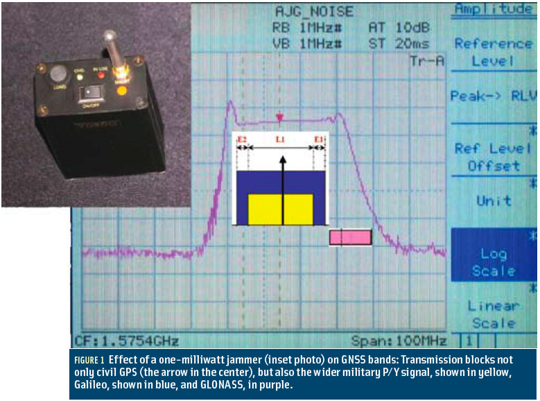
Figure 1 (above, right) shows a screen shot of the total satellite constellation that we simulated during the test.
Our tests mirrored a few general tests and may be described as follows:
1. After receiver tracking loops are designed, we would need to check if they deliver correct observations, such as code phase, carrier phase, Doppler, and carrier-to-noise ratio (C/N0). Using a simulator we know the true observations and directly compare them with those measured epoch by epoch.
This test may be possible to do with live satellites, but with much greater effort and less usable results. Such a test would require us to survey the antenna position in advance, collect the predicted ephemerides, and calculate a predicted range to a satellite and Doppler shift.
This procedure, however, would not guarantee definitive results. For instance, the satellite orbits can be predicted very precisely to satisfy needs of such tests, but the satellite clock predictions may not be so precise and reliable. Consequently, those satellite clock errors will, in effect, show up as incorrectly predicted orbits. Also, separating the receiver hardware–related measurement biases from the satellite hardware and signal propagation–related measurement biases is difficult with this approach.
2. When we are working on a receiver’s navigation processor, we may wish to optimize the equipment’s ionospheric and tropospheric error compensation. In the corresponding test we can toggle the ionospheric and tropospheric errors in a simulator, and the user can directly assess the accuracy and performance of the ionospheric and tropospheric correction algorithms implemented in the receiver.
3. While debugging a navigation processor, we also can compare an encoded navigation message with one decoded by the receiver side by side to ensure the correctness of our decoding algorithm.
4. We should be also interested in measuring receiver sensitivity. We can, in such tests, change signal power level at predefined levels and see how the receiver will react in terms of tracking, acquisition, and navigation.
5. We can also simulate numerous non-standard situations and signal errors to see how our receiver reacts to them.
These types of test are nearly impossible to do with live satellite signals but are rather conventional with simulators, providing that the simulator supports the correspondent functions. Knowing the true model (discussed in Part 2 of this series) and being able to control the signal environment offers many advantages.
The list of possible tests is much longer, and most of them are either impossible or less effective with live satellites.
Record and Playback System: The Recording Function
Record and playback systems (RPSes) have appeared recently as an alternative solution for simulation. They also sometimes referred to as “record and replay systems,” a somwhat inaccurate term because such systems don’t replay the satellite signal, but rather play back the recorded signal. The played back recorded signal could be quite different from the original satellite signal.
An RPS should not be confused with a simulator, because it lacks one of the three simulator’s main features — a controlled environment. That is, unless it plays back a simulated signal, a possibility that we will look at later.
In general an RPS provides a convenient means for repeating a test with live satellites. However, all disadvantages related to live satellite tests are inherited in RPS tests. The two main disadvantages are the absence of control over signal parameters and lack of knowledge of the true model. Only the first test among those we have mentioned earlier could be conducted with an RPS.
. . .
How Good Is an RF Signal On a Disk?
Before we go further, we should look at this recorded RF signal in detail. How good is it?
Here we have a situation similar to the comparison of analog and digital cameras that we used earlier in discussing simulator types. The digital representation of an RF signal, recorded on storage media can be as good as is required.
We convert analog signals to digital ones because a digital signal is easy to analyze, it is more accessible, and our digital instruments are much more precise than analog tools. For years designers have been using oscilloscopes and spectrum analyzers, which work with digitized signals. In fact, if properly done, this signal conversion imposes no limitations at all.
So, let’s look at how an RF signal is transferred to a digitized IF signal. Firstly, the RF signal is down-converted, an operation that keeps all signal features intact and just moves the signal to a lower frequency.
. . .
RPS: The Play Back Function
An RPS is capable of playing back a previously recorded signal. This may come, however, at a price.
When we are testing a receiver with an RPS, we are adding an extra front end — actually two extra front ends, the record and the playback elements — in front of the one under test. In that case, the RPS acts as an extra filter between a satellite signal and the receiver being tested.
. . .
RPS: The Signal Generation
All the limitations related to live satellites are no longer valid if an RPS plays back a simulated signal. In this case the RPS effectively acquires most of the same functionality as a simulator. In order to simulate such signals, we use a PC-based DIF signal generator, the design and functionality of which we described in Part 2 of this series.
Similar to a simulator, which by definition creates a signal indistinguishable from that transmitted by a live satellite, a DIF signal generator creates a DIF file indistinguishable from that recorded by RPS or RF recorder. The generated DIF signal can be played back in the same way as a satellite signal recorded from live satellites.
With such an approach a user still is not being able to control any parameters in real time in the course of a simulation. By contrast, with a conventional simulator we can adjust power for specific satellites or channels in real-time and watch how our receiver reacts to those changes.
. . .
RPS: Mixing Simulated and Real Signals
An interesting feature brought by a RPS system is the possibility of combining a simulated signal with a live satellite signal. This feature can be used in two main application areas — for research into interference and for designing new GNSS systems.
Artificially generated noise or signals can be combined with recorded live satellite signal to simulate interference conditions. This approach has advantages in comparison to that where both signals are simulated. However, as we described in the previous section, high values for the quantization parameter of the artificial signals would be required.
. . .
Jamming Environment Simulation
Thales Avionics has constructed an advanced test to simulate a jamming environment. . . . This is another example of mixing signals for research purposes. In this case, all the mixed signals — involving GPS and Galileo signals — are simulated.
The test was built around a GPS/Galileo RF simulator to research the performance of a multi-antenna, antijamming aviation receiver. The system allows operators to control the simulated distance to a jamming source by adjusting signal power in real time. It also enables control the direction of arrival of a jamming signal by adjusting the phase of each reference clock in the signal generators.
. . .
Simulator Specification Parameters
Here we consider specification parameters mostly for RF simulators. Only some of the parameters of a signal generated from an RPS can be guaranteed because the recorded signal came from a real satellite — which generally is out of reach of user control.
Some parameters also may be less relevant for an RPS because the features of RPSes that we described earlier may mask most of these parameters. So, in the case of RPSes, we will consider only a small part of these parameters.
. . .
Does Size Really Matter?
Essentially the physical dimensions of simulation equipment are always in the specification. For lab tests the dimensions are more flexible as the unit merely needs to fit into a standard lab rack mount. In case of RPSes, field recorders need to be smaller rather than bulky.
Nonetheless, all this equipment is not intended for a consumer market and, unless it is a manufactured in quantities, a small size may signify a compromise of quality. If we look, for example, at computers, desktop solutions still provide better performance specifications than laptops and far better one than handheld computers or smartphones.
What really matters in simulation equipment today is the graphical user interface (GUI). A user-friendly, intuitive GUI is not a luxury any more; it is a requirement. We no longer can say that simulator users must be specialists and able to guide themselves through a complicated set of user actions or expect to struggle along without a user-friendly GUI.
. . .
Conclusion and Guidelines
In looking at options for test solutions, a digital RF simulator is still the optimal one in most areas. When choosing one, make sure that all desired tests are supported and all important models and parameters are editable and configurable. Don’t underestimate the importance of the GUI, because it will give you better control over the tests and save you time.
RPSes and RF recorders give a possibility to record valuable and unique signal data and in that respect represent useful and powerful tools for R&D.
When playing back RF signals from an RPS, make sure that its parameters satisfy your test requirements. Be aware that the RF signal played back from an RPS is changed in respect to the original satellite signal and is, in general, inferior to a signal produced by a simulator. Make sure that the RPS allows you to conduct all required tests, because most of the standard tests cannot be supported by recording and playing back live satellite signals.
For a solution in which a signal for playback is generated in the software, look more carefully at the DIF generator in charge. As with an RF simulator, make sure that all important models and parameters are in place, editable, and configurable.
For many R&D tasks, where the RF part can be bypassed, an RPS with DIF playback may present a very useful simulation solution. In this case, a recorded DIF signal can be streamed to a baseband processor of the receiver under test bypassing two extra RF front ends.
For the complete story, including figures, graphs, and images, please download the PDF of the article, above.
Additional Resources
Tsujii, T., and T. Fujiwara, Y. Suganuma, H. Tomita, and I. Petrovski, “Development of INS-Aided GPS Tracking Loop and Flight Test Evaluation,” 2009 International Symposium on GPS/GNSS, Jeju, Korea, November 4–6, 2009.


