Q: Does the magnitude of the GNSS receiver clock offset matter?
A: It is well known that GNSS receiver clocks drift relative to the stable atomic time scale that ultimately defines a particular GNSS system in the first place. GNSS receiver manufacturers, however, try to limit the magnitude of the time offset to within some predefined range.
This raises the question of whether the magnitude of the offset is significant or not. The short answer is “it depends,” and this column looks at some of the aspects that you may want to consider in your application.
Quick Review
Before looking at the effect of the receiver clock offset on performance, it helps to remind ourselves what the clock offset actually is. In brief, the offset represents the difference between what time the receiver thinks it is, and the true time, with the latter determined by the underlying GNSS atomic time scale.
As is well known, this difference is estimated as a nuisance parameter along with the receiver position. By analogy, the receiver clock drift (time derivative of the clock offset) is often also estimated as a nuisance parameter along with the receiver velocity.
Given that estimates of the offset (and drift) are available within the receiver, GNSS receiver manufacturers adjust the receiver’s estimate of time in order to limit the magnitude of the offset to within predefined limits. Two approaches are possible in this regard. First, the receiver can “steer” the oscillator in order to drive the clock drift to approximately zero, in which case the offset is constant to within the level of noise and tracking jitter.
Second, and perhaps more common, the receiver introduces discrete jumps in the receiver’s estimate of time. These jumps typically occur when the clock offset exceeds one millisecond in magnitude and hence are often called millisecond jumps. In some cases, the jumps are larger than one millisecond, but are always an integer number of milliseconds (in the author’s experience).
With this in mind, we now turn to the three main uses of the receiver’s estimate of time. The first is to compute the time at which the signal left a satellite, which is required to compute the position of the satellite and, in turn, the approximate distance (pseudorange) between it and a receiver. The second is to time-match data from multiple sources. Finally, a receiver’s time estimate is also used to time-tag the user’s position. Each of these deserve some further attention.
Computing Transmit Time
Let us look briefly at how pseudoranges are computed within a receiver. First, the receiver calculates the transmit time of the signal (i.e., the time the signal left the satellite), using a combination of the received navigation message and the receiver’s delay lock loop (DLL, the code tracking loop).
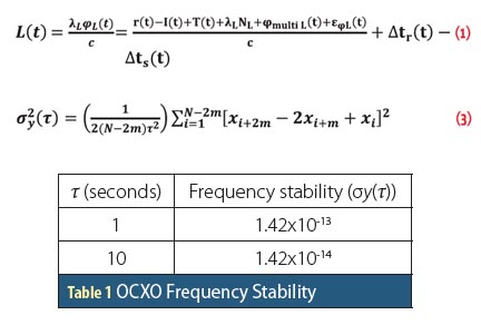
Next, when the receiver thinks it is time to generate measurements, the transmit time is subtracted from the current receiver time. This time difference, when scaled by the speed of light, produces the pseudorange. For the purpose of this work, it can be written as
P = c · (tRxˆ – tTx) = ρ + c · dt + ε
where P is the pseudorange measurement, c is the speed of light, tRxˆ is the receiver’s estimate of time, tTx is the time of transmission (assumed to be perfect, realizing that a receiver can compute this to a high degree of accuracy using the satellite clock correction in the navigation message), ρ is the geometric range/Cartesian distance between the receiver and the satellite, dt is the receiver clock offset, and ε is the sum of all errors (negligible in the context of this article).
The good news is that we can use Equation (1) in reverse to compute the transmit time from pseudoranges time-tagged with tRxˆ. Correspondingly, the transmit time can always be obtained perfectly regardless of the magnitude of the receiver clock offset. In turn, the satellite position is computed without introducing errors in excess of those of the broadcast ephemeris parameters.
Time-Matching Measurements
Differential, or relative, positioning between two (or more) users involves differencing measurements between the receivers involved. Intuitively, this difference should be formed using measurements collected at the same time at all receivers. Obviously, the variations in receivers’ clock offsets means that, in general, this does not happen. With this in mind, the relative clock offsets between the receivers is important.
When differencing data from two receivers, we assume that the measurement errors between them are largely the same. The spatial separation of the receivers results in some residual errors (i.e., not all errors completely cancel). Similarly, if the two receivers’ measurements are not perfectly time synchronized, the temporal variability of GNSS errors will introduce an additional residual error.
Residual error from spatial separation is normally much larger, but the effect stemming from non-synchronized measurements is nevertheless also present. For typical receivers (i.e., maximum offset of one millisecond per receiver, or a worst-case relative offset of two milliseconds), the increase in the residual error due to time synchronization is negligible.
However, because some receivers allow the user to disable receiver clock corrections, the relative clock offset could conceivably become more significant. In this case, the increased residual error may become large enough to adversely affect the carrier phase ambiguity resolution process in high-accuracy applications.
Tagging User Positions
This is perhaps the most obvious use of the output receiver time estimate, but it is arguably the one that is most sensitive to receiver clock offset. Specifically, the existence of the receiver clock offset means that the computed position is inconsistent with the measurement time. That is, the computed position actually corresponds to the true measurement time, not the estimated measurement time.
To get a feel for this, consider a typical receiver with a maximum clock offset of one millisecond (ms). Assuming the user is traveling at 100 kilometers per hour (km/h), a one-millisecond timing error is equivalent to approximately 2.8 centimeters (i.e., 100 km/h x 1 ms). For many commercial applications, this error will be well below the noise. However, for high-accuracy, carrier phase-based applications, this level of error may be quite significant.
Of course, the problem is worse if the clock offset is larger. For example, at least one GNSS manufacturer only resets the receiver clock when the offset exceeds 100 milliseconds. In this case, the resulting position “error” is nearly three meters. This level of error may represent a large proportion of many mass-market applications.
The problem is also compounded if a differential solution is required and both receivers are moving. Perhaps the best example of this is GNSS attitude determination in which the relative position of two or more receivers is computed in a local level frame using carrier phase data (with fixed ambiguities), and then the transformation between the local level frame and a pre-defined vehicle frame is computed.
Returning to our vehicle traveling at 100 km/h, for a worst-case relative clock offset of two milliseconds, the relative positioning error between two receivers is approximately 5.6 centimeters. If we assume a one-meter baseline between receivers (attitude determination systems typically use fairly short baselines), this could result in a worst-case attitude error of about 3.2 degrees (i.e., 5.6 centimeters over 1 meter), which would typically far exceed the nominal performance specifications for such a system.
A Parting Thought
The previous sections have identified how a GNSS receiver clock offset could affect performance. Overall, because GNSS receivers bound the offset within fairly tight constraints (typically one millisecond or less), the corresponding effect on the computed position is usually negligible for all but the most demanding applications.
However, one last thing needs to be considered: the estimation of the receiver clock offset. If the receiver uses a Kalman filter for data processing, which is often the case, care must be taken to properly detect and account for millisecond jumps prior to incorporating measurements into the filter.
Without this data screening process, the filter will effectively see an error of about 300 kilometers (one millisecond) or more on all measurements; however, because the clock offset is usually fairly well constrained — even for a low-performance oscillator — the ranging errors will ultimately end up in the computed position and introduce a very large position error (if the solution is stable at all).


