Global navigation satellite systems provide position, velocity, and time (PVT) solutions to users whose receivers calculate position based on one-way ranging from satellites. As is well-understood, a key step in the positioning process involves a determination of the difference between the time of signal transmission identified in the satellite’s broadcast navigation message and the time of its reception by user equipment.
Global navigation satellite systems provide position, velocity, and time (PVT) solutions to users whose receivers calculate position based on one-way ranging from satellites. As is well-understood, a key step in the positioning process involves a determination of the difference between the time of signal transmission identified in the satellite’s broadcast navigation message and the time of its reception by user equipment.
The accuracy of time of transmission depends on a satellite’s onboard clock stability, with the clock’s short-term stability affecting — among other applications — precise point positioning. Hence, it is very important to monitor the short-term stability of in-orbit satellite clocks and find out the onboard time error compared to the navigation system time.
GNSS satellites transmit navigation signals on L-band and/or S-band frequencies. Highly accurate receivers track carrier phase as well as code phase of transmitted signals and use the carrier phase observables to determine an in-orbit clock’s short-term stability.
These calculations estimate deterministic errors due to geometrical range and range rate by using precise satellite ephemeris data to estimate the short-term stability of the satellite clocks. However, the algorithms employed in these estimation techniques are limited during in-orbit testing of satellite carried out after the launch when precise ephemeris data may not be available for processing. So, it is very important to characterize the onboard clock for initial operations of navigation satellites once in orbit.
This article proposes a mathematical model to remove deterministic errors, without using satellite ephemeris data, to analyze the short-term stability of GNSS in-orbit clocks in the presence of adverse environmental and equipment effects. The proposed technique is useful for geostationary orbit (GEO) or geosynchronous orbit (GSO) navigation satellites where the carrier doppler rate remains constant for short periods of time due to the orbital characteristics.
Description of the Case Study & Algorithm
We chose observation times in which the doppler rate remains constant and free from higher order (greater than second order) doppler effects. In this way, to estimate short-term stability (≤100 seconds) we are able to remove the effect of carrier doppler without using a satellite ephemeris. Hence, from the carrier phase observations, the combined effects of doppler, doppler rate, onboard clock, and receiver clock deterministic errors are removed by a least-squares estimation method.
For analytical purposes, we used typical GEO/GSO navigation satellite signals-in-space (SIS) in a case study, comparing the measured results of the in-orbit satellite clock’s short-term stability against a time reference on the ground.
We begin by modeling carrier phase observables. In our analysis, we used the L5 band SIS to estimate onboard clock stability by measuring the carrier phase differences between the onboard-transmitted carrier phase and that received at the user equipment, which provides a satellite-to-receiver range measurement in terms of the number of carrier phase cycles.
Onboard transmitted carrier phase is generated from highly stable atomic frequency standard, and the receiver measures carrier phase using a reference source, typically a crystal oscillator. These measurements are affected by various parameters such as integer cycles ambiguity, ephemeris errors, satellite clock bias, receiver clock bias, ionosphere effects, troposphere effects, and receiver measurement noise.
The carrier phase observable model equation is
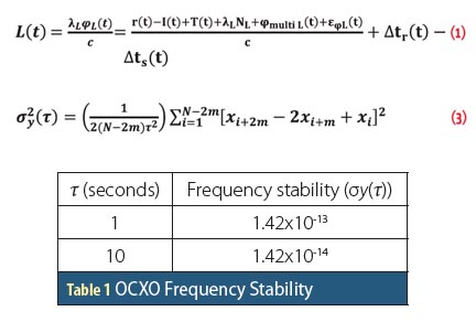
Equation (1) (see inset photo, above right, for equations)
where:
L = measured carrier phase at L5 band in seconds
λL = wavelength at L5 carrier frequency
φL = measured carrier cycles
r = geometrical range between satellite and receiver
c = speed of light
NL = integer cycle ambiguity
Δts = satellite clock bias (bias, drift, drift rate and relativistic error)
Δtr = receiver clock bias
I = ionosphere delay in meters
T = troposphere delay in meters
φmulti L = multipath delay in meters
εφL = carrier tracking error in meters.
A receiver cannot measure the absolute carrier phase difference between satellite and receiver. It measures carrier phase within 0 to 360 degrees of one cycle as a first measurement and then keeps track of change in carrier phase over a period of time. Hence, it has an ambiguity of integer cycles (as a residue of range) that can be estimated based on precise ephemeris parameters and code phase measurements.
Satellite clock errors are deterministic errors, which can be estimated, based on least-squares estimation method. Receiver clock errors are also deterministic in nature. To estimate onboard clock performance, the receiver clock stability should be at least one order of magnitude better than onboard clock stability so that the effects of receiver clock stability do not introduce uncertainties into the carrier phase measurements.
Ionosphere delay is inversely proportional to square of frequency and varies with local time and season. Ionosphere delay adds maximum range errors on carrier phase measurements over a day. Ionosphere delay can be removed using dual frequency measurements.
Troposphere delay affects signals at up to 50 kilometers of altitude and contains delays due to wet and dry components, which can be estimated based on available statistical models or local measurements. Multipath also affects carrier phase measurements, but its contribution will be much less compared to other error sources. The carrier-to-noise density (C/N0) of the link will add to the carrier tracking error on carrier phase measurements.
Analysis Time Period for Estimation of Constant Doppler Rate
To estimate the short-term stability (≤100 seconds) of an in-orbit satellite clock ephemeris parameters are assumed to remain constant. Due to relative motion between satellite and receiver, doppler and doppler rate keep varying with time. So, without the knowledge of precise ephemeris parameters, doppler and doppler rate can not be estimated deterministically. In turn, these time-varying parameters, if not compensated for in carrier phase measurements, will affect the estimation of satellite clock stability.
To solve this problem, we used GEO/GSO satellites’ carrier phase data for periods during which the doppler rate is constant so that higher order effects would not be present and effects due to relative motion on carrier phase measurement could be estimated using a least-squares method. This approach is valid only for navigation satellites in GEO/GSO orbit and not applicable for satellites in middle Earth orbits (MEO).
We used longer-duration double-differenced carrier phase measurements to determine the constant doppler rate in order to estimate clock stability. This process was carried out for two successive days, and approximately 350 seconds (analysis time) of data from each day were used to estimate onboard clock short-term stability using the SIS.
Estimation of Deterministic Errors. As discussed in the section describing our modeling of carrier phase observables, deterministic errors arise from the satellite and receiver clocks as well as those related to relative motion. Our analysis used the stable oven-controlled crystal oscillator (OCXO) from a phase noise measuring instrument as reference source for the payload test receiver (PTR).
The OCXO’s short-term stability is one order of magnitude better than the onboard clock in the observed navigation satellite. So, the effect due to receiver clock stability is nullified in the carrier phase measurements, which were used to estimate and remove the combined deterministic effects of onboard clock errors, receiver clock errors and errors related to relative motion before estimation of clock stability. The combined deterministic error (Ce) model is given in equation (2):
Ce = Δtr – Δts + d0t + d1 t2 (2)
where, Δts and Δtr are the satellite clock bias and receiver clock bias, respectively. d0 (sec/sec) and d1 (sec/sec2) are normalized doppler and doppler rate, respectively.
Frequency Stability. The Allan deviation is the most important time domain measure of frequency stability. Similar to the standard deviation, it is a measure of the fractional frequency error and has the advantage of converging for most types of random clock noise.
In this analysis, we used an overlapped Allan deviation mathematical tool to estimate frequency stability. The result is usually expressed as the square root of the Allan variance, using two samples of fractional frequency errors to estimate the stability of frequency. The overlapped Allan variance in terms of phase data is given as follows:
Equation (3)
where, xi is the ith sample of the N phase data spaced by the measurement averaging time τ = mτ0 (seconds). m is an averaging factor, and τ0 is the basic measurement interval. The relationship between fractional frequency values and phase data is yi = (xi+1–xi)/2.
Because the Allan variance is two-sample variance, any bias and drift components in the phase data will cancel out and thus not affect frequency stability estimation. However, the drift rate on phase data will affect the frequency stability estimation, as discussed in the articles by D. W. Allan and M. Y. Shin et alia listed in the Additional Resources section near the end of this article. Hence, before estimation of the frequency stability of an SIS signal, all possible deterministic errors must be removed from the carrier phase observables.
Test Setup
In the test setup, we used the PTR to obtain the carrier phase observables. The carrier phase measurement accuracy of receiver is better than one millimeter, which corresponds to a white noise less than 3×10-12 at one second. Short-term stability of the OCXO from the phase noise measuring instrument, which was chosen as reference source for measurements, is one order better than observed navigation satellite onboard clock and its stability is given in Table 1 (see inset photo, above right).
A choke ring antenna was used to receive the L5 band signals. Benefit of using choke ring antenna is stable phase center and higher multi-path rejection capabilities. Thus effects due to receiver measurement error, receiver clock stability and multi-path are negligible on carrier phase measurements. Figure 1 shows the test setup for estimating the clock stability.
Results
The carrier phase-observables model shows that carrier phase observables are affected by ionosphere delay as well as troposphere delay. Troposphere delay remains constant for short time durations. The change in ionosphere delay (for a short time period) as compared to the range rate is negligible.
As mentioned earlier, our analysis used at least 350 seconds of data for the estimation of the short-term stability of atomic clock, which will average out random errors. Hence, any change in ionosphere delay or troposphere delay up to 15 millimeters per second will not affect the estimation of short-term stability of the in-orbit clock. Integer cycles ambiguity is also a constant term, which will not affect estimation of clock stability. As discussed earlier, any multipath error and receiver measurement error are also ignored. Now, only deterministic errors due to onboard atomic clock, receiver clock, doppler, and doppler rate need to be estimated and removed from carrier phase observables as per the model proposed earlier.
In analyzing the results, navigation data is not used to estimate the short-term stability of clock. L5 band carrier phase data of a typical GEO/GSO navigation satellite has been collected through the PTR on day of year (DOY) 36 and 37 of 2014, which are shown in Figure 2 and Figure 3, respectively. The carrier phase was measured at a one-second rate. Double differencing of carrier phase data, which results in nothing but the drift rate, is also shown in Figures 4 and 5.
Our analysis selected data from the interval 5600-5950 seconds from the DOY-36 data set and the interval 4050- 4400 seconds from DOY-37 data set for estimation of clock stability, as no higher order errors are present in carrier phase observables during those intervals and the doppler rate is also constant. Figure 6 and Figure 7 shows the fractional frequency error after removing deterministic errors from carrier phase observables as per equation (2) using least-squares estimation method. Figure 8 shows the estimated stability of the onboard clock using one-way carrier phase measurement compared with performance of the time reference on the ground.
Conclusions
This article presented a technique to estimate short-term stability of an onboard satellite clock using one-way carrier phase measurements given a constant carrier doppler rate during the period of analysis. This technique estimates the combined deterministic errors, i.e., satellite and receiver clock errors, doppler and doppler rate. Results are shown for typical GSO navigation satellite SIS compared against ground results. Accuracy of this technique to estimate clock stability is 1×10-13, which is one order of magnitude better than ground performance. This technique will find applications during in-orbit testing of any navigation satellite constellation having GEO or GSO satellite.
Acknowledgments
The authors would like to express sincere gratitude to Shri D K Das, deputy director, ISRO SATCOM & Navigation Payload Area (SNPA), for his encouragement during this work. They would like to thank Shri Sumitesh Sarkar, group director, SAC Satcom & Navigation Payload System Engineering Integration & Check Group (SNSICG), for his valuable guidance and comments during this work. They would also like to thank Shri Alak Banik, program director for the Indian Regional Navigation Satellite Systems, for providing insight of atomic clock.
Additional Resources
[1] Aeroflex, COMSTRON PN9100A Frequency Synthesizer Module
[2] Allan, D. W., “Time and Frequency Time Domain Characterization, Estimation, and Predication of Precision Clocks and Oscillators”, IEEE Transactions on Ultrasonics, Ferroelectrics, and Frequency Control, vol. UFFC-34, No. 6, 647–654, November, 1987
[3] Gonzalez, F., and P. Waller, “Short Term GNSS Clock Characterization Using One-Way Carrier Phase”, Frequency Control Symposium, Joint with the 21st European Frequency and Time Form, pp. 517–522, IEEE International, May 2007
[4] Hesselbarth, A., and L. Wanninger, “Shortterm Stability of GNSS Satellite Clocks and its Effects on Precise Point Positioning”, Proceedings of ION GNSS 2008, pp. 1855-1863, Savannah, Georgia, USA, 2008
[5] Shin, M. Y., and C. Park and S. J. Lee, “Atomic Clock Error Modelling for GNSS Software Platform,” Proceedings of the Position, Location and Navigation Symposium (PLANS) 2008, pp. 71–76, IEEE/ION, May 2008
[6] Waller, P. “In-Orbit Performance Assessment of GIOVE Clocks”, Proceedings of 40th Annual Precise Time and Time Interval (PTTI) Meeting, pp. 69-82, December 2008


