
Interference mitigation techniques should protect GNSS receivers from interference and jamming without biasing their final position, velocity and timing solution. This column analyses five popular interference mitigation techniques, including the Adaptive Notch Filter (ANF) and Pulse Blanking (PB), evaluating their impact on pseudoranges and on the final position and timing solution. Several GNSS modulations are considered, showing the advantage of using GNSS signals with similar spectral characteristics.
GNSS receivers are now required to operate in complex radio frequency (RF) environments and to withstand significant levels of interference and jamming. For these reasons, receiver manufacturers are now implementing interference mitigation techniques able to improve receiver performance in the presence of jamming. Among the different techniques available in the literature, the most popular ones are probably pulse blanking (PB), to reduce the impact of pulsed interference, and notch filtering for continuous wave (CW) removal. While these techniques can significantly improve receiver robustness, they can also introduce biases and distortions. For example, the notch filter is known to introduce biases at the measurement level. When the frequency of the filter notch is known and fixed, these biases can, however, be determined and compensated for during the process of measurement generation.
A review on interference mitigation can be found in the article published in the September 2017 issue of Inside GNSS listed in Additional Resources. The review also includes the framework of robust interference mitigation (RIM) that exploits principles from robust statistics. Techniques such as PB and frequency excision belong to the class of RIM techniques.
While significant work has characterized interference mitigation techniques at the signal-processing level, limited analysis has assessed their impact in the measurement and position domains. This article fills this gap and analyzes five popular interference mitigation techniques at the measurement and position levels, studying the potential introduction of biases. The impact on the timing solution has also been analyzed.
The five interference mitigation techniques considered include the Adaptive Notch Filter (ANF), a form of notch filter where the notch frequency is dynamically estimated, and four RIM techniques. The impact of the techniques is assessed considering several GNSS signals on two frequencies: on L1 (1575.42 MHz) the GPS L1 C/A signal and the binary offset carrier (BOC) modulation adopted by the Galileo E1B/C and the Beidou B1C signals are considered, while the wideband binary phase shift keying (BPSK) modulation adopted by the Galileo E5B and the Beidou B2bI signals is analyzed on the 1207.14 MHz frequency.
The analysis highlights the complex interaction between the different GNSS modulations, interference mitigation techniques, measurement generation and position computation.
Interference Mitigation Techniques
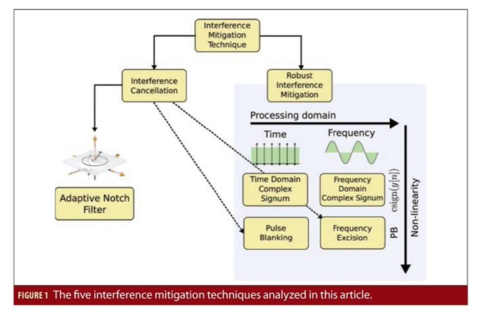
The five interference mitigation techniques considered here can be classified according to the schematic representation provided in Figure 1. Interference mitigation techniques can be designed according to the interference cancellation (IC) principle: the mitigation algorithm estimates at first the interfering signal that is then removed (canceled) from the input samples. The ANF uses this principle and estimates the parameters of frequency modulated signals. IC mitigation techniques usually adopt a signal model for the interfering signal. The ANF assumes that the interfering signal has a practically constant amplitude. Alternatively, mitigation techniques can be designed using principles from robust statistics. In this case, the interfering signal is at first projected into a transformed domain where it is expected to assume a sparse representation, i.e. to affect a limited number of samples that can be treated as outliers. A non-linearity is then used to mitigate the impact of these outliers. Finally, an inverse transform is used to bring the signal back into the time domain. Techniques implementing these three operations belong to the class of RIM. PB and frequency excision are obtained when the following non-linearity.

is adopted. Y[k] denotes the signal samples brought into the transformed domain and Th is a decision threshold. When processing is performed directly in the time domain, PB is obtained. If a Discrete Fourier Transform (DFT) is used to bring the samples in the frequency domain, then frequency excision is implemented. Incidentally, PB and frequency excision can also be interpreted as forms of IC where, in the first case, the interference term is modeled as a sequence of pulses and in the second as a combination of complex sinusoids.
In addition to non-linearity (1), we also considered the complex signum non-linearity:

Combining the two processing domains and the two non-linearities a total of four RIM techniques are obtained: time domain pulse blanking (TDPB), time domain complex signum (TDCS), frequency domain pulse blanking (FDPB) and frequency Domain complex signum (FDCS).
IC and RIM techniques are effective when model assumptions are valid, i.e. when the interference signal has an almost constant amplitude for the ANF and when it has a sparse support in the processing domain of RIM techniques. We also consider here the case of pulsed interference. When the DFT is applied to this type of signals and frequency domain RIM is used, the interference term is spread over several samples, the sparsity assumption is violated and receiver performance is actually degraded.
Measurement, Position and Timing
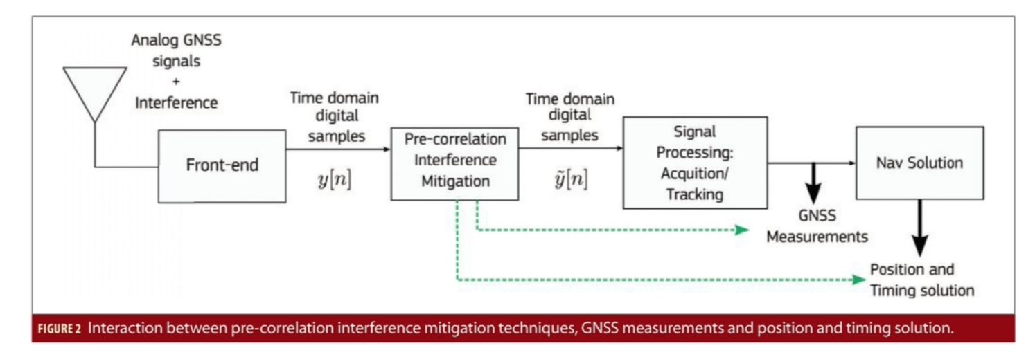
The five techniques considered are pre-correlation approaches that act directly on the samples provided by the receiver front-end. After pre-correlation interference mitigation, a new set of time domain samples is produced and passed to standard acquisition and tracking stages that process the GNSS signals and extract measurements such as pseudoranges, carrier phases and Doppler frequencies. Finally, GNSS measurements are used for computing the user position and clock parameters. In this respect, a potentially complex interaction occurs between pre-correlation interference mitigation techniques, measurements, the position and the clock solution. A schematic representation of the processing stages implemented in a GNSS receiver is provided in Figure 2. The complexity mainly arises from the relative distance, in terms of processing blocks, between interference mitigation, measurement generation and position solution.
For this reason, we adopted an experimental approach coupled with the software defined radio (SDR) paradigm to evaluate the impact of interference mitigation techniques. More specifically, a fully software GNSS receiver was used to process data collected in the presence of jamming and to assess the impact of interference mitigation techniques on the measurements and on the position and clock solution. The datasets collected according to the experimental setup described in the next section have been processed several times using the different interference mitigation techniques and the results obtained have been compared with those provided by standard processing in the absence of mitigation.
In the measurement domain, the analysis focused on pseudoranges and for each interference mitigation strategy, differences between pseudoranges computed with and without mitigation were formed:

where PRdiff[m] is the pseudorange difference at the epoch m and PRMit and PRStandard are the pseudoranges obtained with and without interference mitigation. This approach leads to the cancellation of all common errors preserving the differences introduced by the specific processing scheme. Ideally, interference mitigation techniques should not bias pseudoranges and pseudorange differences (3) should be zero mean. In this respect, we investigated the mean of pseudorange differences.
To analyze the impact of interference mitigation on the position solution, positioning errors were computed for all the processing strategies considered. Since the antenna of the receiver was carefully surveyed, it was possible to compute position errors with respect to the known antenna location. The errors were computed in a local East, North, Up (ENU) frame centered into the antenna reference position. In this way, it was possible to directly compare the position errors and analyse the impact of interference mitigation. The analysis focused on single point positioning (SPP) computed using a weighted least squares (WLS) approach where the weights were determined as a function of the satellite elevation.
Finally, we analyzed the clock bias. In particular, the antenna coordinates were fixed and a clock-only solution was computed. We considered this type of solution since it is usually adopted by GNSS timing receivers that fix at first the user position and compute only the clock bias. The clock time series were then compared.
Experimental Setup
Several experiments assessed the impact of interference mitigation in the measurement, position and clock domains. A SDR front-end collected in-phase/quadrature (I/Q) samples that were then processed using a custom Matlab software receiver.
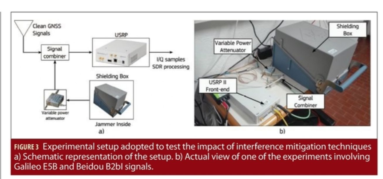
A dedicated experimental setup was developed where a jammer was placed inside a shielding box whose output was connected to a variable attenuator, adopted to generate different jamming power levels. At the beginning of each test, the attenuation was set to a significant value and the amount of jamming power leaking through the attenuator was negligible. In this way, the first part of each test allowed the assessment of the impact of interference mitigation in the absence of interference.
The output of the variable attenuator was then combined with clean GNSS signals collected from a rooftop antenna. In this way, jammed GNSS signals were obtained. A schematic representation of the experimental setup adopted for testing the impact of interference mitigation and a view of one of the experiment conducted is provided in Figure 3.
Three modulations were considered: the BPSK(1) of GPS L1 C/A signals, the BOC(1, 1) modulation adopted by Galileo E1B/C and by the Beidou B1C signals and the wideband BPSK(10) modulation adopted by the Galileo E5B and Beidou B2bI component. For Galileo E1C, Beidou B1C and Galileo E5B signals, pilot processing was implemented. Signals on the L1 frequency were collected with a 10 MHz sampling frequency, whereas the E5B components were collected using a 25 MHz sampling frequency. The Galileo E5B and the Beidou B2bI signals are considered wideband, and the main lobe of their spectrum occupies most of the frequencies captured by the SDR front-end. The custom software receiver generates Receiver INdependent EXchange Format (RINEX) files that were used for the measurement and position domain analysis. The parameters used for the different tests are summarized in Table 1 that also describes the attenuation profile used for each experiment.
Three tests were considered:
• Test 1: performed on the L1 frequency band (1575.42 MHz centre frequency) with a 8 bit quantization. This test was used to analyse the impact of interference mitigation on the GPS BPSK(1) modulation and on the Galileo/Beidou BOC(1,1) component.
• Test 2: also performed on the L1 frequency band but with a 16 bit quantization. This test was conducted to analyse potential differences between 8 bit/16 bit quantization.
• Test E5B: performed on the E5B/B2bI frequency band (1207.14 MHz centre frequency). This test was conducted to analyse the impact of RIM on a wideband GNSS modulation.
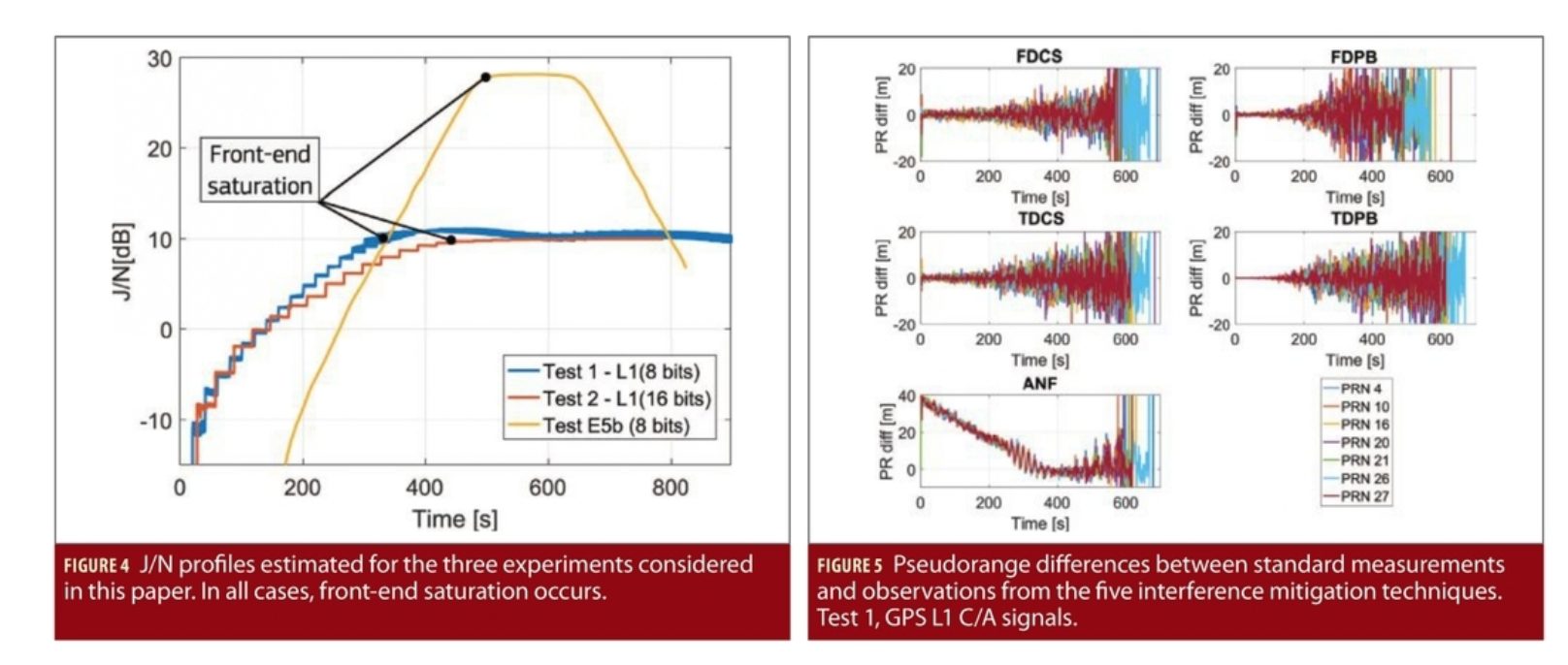
The power profiles obtained for the three tests are analysed in Figure 4 that shows the jamming to noise power ratio (J/N) estimated from the samples collected using the SDR front-end. While a linear J/N profile was expected (see the corresponding parameters in Table 1), in all three cases the front-end experiences saturation. In this case, the jamming signal is so powerful to exceed the capabilities of the front-end quantization function that effectively clips the received samples to the minimum and maximum values allowed by 8/16 bits. Front-end saturation introduces significant signal distortions that further impact receiver operations. For the third test, the jammer attenuation was increased again after 550 seconds from the start of the test.
Additional details on the three tests and on the properties of the jamming signals used in each experiment can be found in the paper presented by the authors at the International Technical Meeting (ITM) of the Institute of Navigation (ION) and listed in Additional Resources.
Experimental Results
The pseudorange differences obtained for Test 1 and for GPS L1 C/A signals are shown in Figure 5. The four upper boxes correspond to the differences obtained for RIM techniques: in these cases, the time series are zero mean and no clear trend is introduced by the mitigation techniques. The first 200 seconds of the test are characterized by J/N values lower than 5 dB, which make the jamming component negligible. In this portion of the test, pseudorange differences oscillates around zeros with variations lower than 5 metres. The variance of the pseudorange differences increases with the J/N: this fact is expected and reflects the increased equivalent noise caused by the jamming component. The zero mean property observed for RIM techniques confirms the theoretical result obtained by Borio and Closas in their paper listed in Additional Resources.
RIM techniques do not bias the Cross-Ambiguity Function (CAF), the main quantity evaluated by the acquisition and tracking blocks. The CAF is a generalized version of the correlation function and has a main peak in correspondence of the Doppler frequency and code delay of the signals acquired and tracked by the receiver. Since the CAF is not biased by RIM techniques, also the pseudoranges are not biased by this type of approaches. The results in the four upper boxes of Figure 5 confirm this theoretical finding.
The impact of the ANF is analysed in the bottom left box of Figure 5: in this case, a significant bias can be observed. The ANF delays pseudoranges and introduces a time-varying bias. At the beginning of the test, the impact of jamming can be neglected and the only interfering term is a CW generated by the clock of the SDR front-end used for the data collection. This CW has a frequency equal to 1575 MHz, which is close to the GPS L1 C/A centre frequency. Thus, the ANF significantly impacts GPS L1 C/A signals. As the jamming power increases, the adaptive block of the ANF converges to a different solution leading to different biases on the pseudoranges. Indeed, the time-varying behaviour of the ANF is due to the changing jamming conditions occurring in Test 1.
While it is difficult to theoretically predict the bias introduced by the ANF, this delay is common to all measurements and a limited impact is found on the SPP solution, as better analysed in the following. Indeed, most of the bias introduced by the ANF is absorbed by the clock bias term.
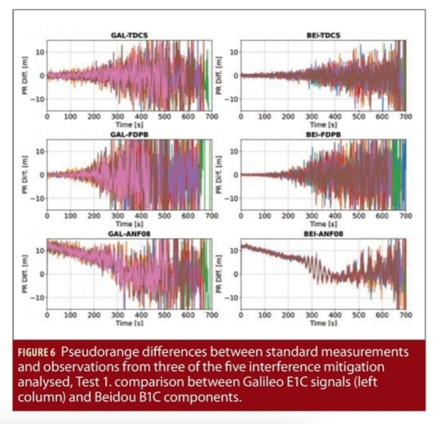
The impact of interference mitigation techniques on Galileo E1C and Beidou B1C pseudoranges is analysed in Figure 6. In the figure, two RIM techniques and the ANF are considered. Also in this case, RIM techniques do not introduce biases on the measurements whereas the ANF delays the pseudoranges. The delay introduced on the Galileo E1C and Beidou B1C signals is however different from that observed for the GPS L1 C/A components. This difference is due to the different spectral interaction between the ANF transfer function and the BOC and BPSK modulations adopted by the Galileo E1C/Beidou B1C and GPS L1 C/A signals, respectively.
At the beginning of the test, the delay introduced by the ANF on the Galileo/Beidou pseudoranges is about 10 metres against the 35 metres observed for the GPS L1 C/A components. The lower delay observed for Galileo/Beidou signals is due to the fact that the ANF notch is placed around 1575 MHz that it close to a spectral zero of the BOC modulation that is less distorted than the GPS L1 C/A signals. Thus, a lower delay is observed.
Far from its notch, the ANF transfer function is almost flat with a negligible group delay. For this reason, signals occupying spectral regions far from the ANF notch are less delayed. As for the previous GPS case, the biases introduced by the ANF are mostly common to all Galileo/Beidou pseudoranges and will be absorbed by the clock bias term in a Galileo- or Beidou-only solution. In a multi-constellation solution, these delays will be absorbed by the inter-system bias estimated by the receiver. Figure 6 also provides a direct comparison between Galileo and Beidou pseudorange differences: the same delay is introduced by the ANF on the two components. In this case, only the BOC(1,1) component of the Beidou and Galileo signals is processed and the ANF affects in a similar way modulations with the same spectral characteristics.
This result shows the advantages of using signals with the same spectral characteristics: the same delay is introduced by the ANF on interoperable modulations. In this way, the inter-system bias between Galileo and Beidou is not affected by the ANF allowing the use of advanced positioning algorithms exploiting the stability of inter-system biases. Beidou pseudorange differences are less noisy than the Galileo ones. This fact is due to the longer integration time (10 ms) adopted for the Beidou signals.
Results similar to those obtained for Test 1 were obtained in Test 2. These results can be found in our paper listed in Additional resources.
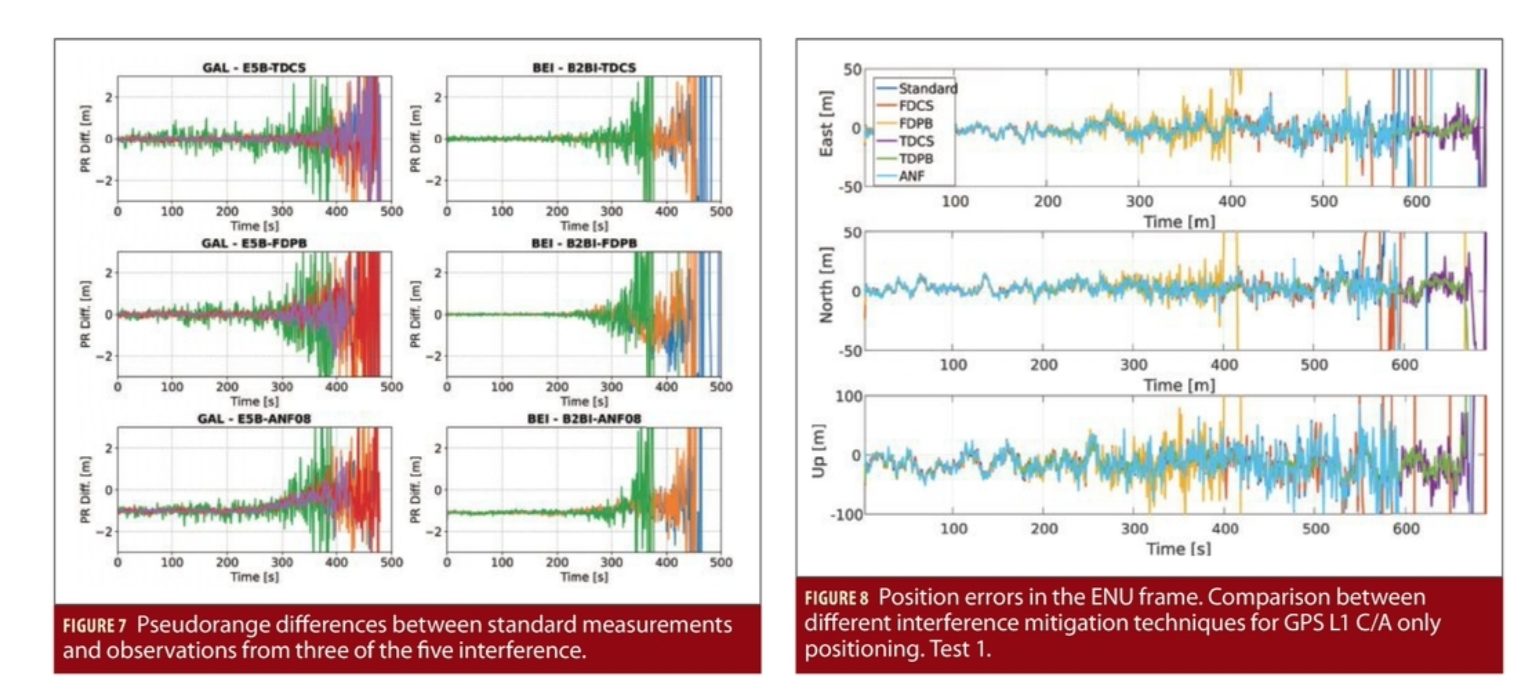
The results obtained for the test on the E5B/B2B frequency are shown in Figure 7: similar results are observed for the Galileo and Beidou signals. As for the previous cases, RIM techniques do not introduce biases in the pseudoranges and zero-mean differences are obtained. Moreover, since the Beidou and Galileo signals adopt the same modulation, the same delay is introduced by the ANF.
When comparing Test 1 and Test E5B results, significantly lower differences are observed in the second case. More specifically, the ANF introduces a bias of about a metre, whereas RIM techniques lead to average pseudorange differences in the millilitre level. These significantly lower differences are due to the wideband nature of the E5B/B2I signal and to the higher accuracy of the resulting pseudoranges.
Position solutions have been analysed for Test 1 in Figure 8 that shows the position errors obtained using GPS L1 C/A pseudoranges. From the figure, it emerges that all five interference mitigation techniques do not bias the final SPP solution and, at least under low jamming conditions, all the time series are characterized by the same trend. The standard solution without mitigation provides reasonable position estimates for the first 550 seconds of test whereas time domain RIM techniques improve receiver performance leading to reduced errors for the first 700 seconds.
For Test 1, the jamming power was increased of 1 dB every 20 seconds. This implies that time domain techniques provided a margin of about 7.5 dB in terms of resilience to jamming power. In addition to this, the receiver front-end started saturating after about 400 seconds from the beginning of the experiment. Thus, time domain RIM allows receiver operations even in the presence of significant levels of front-end saturation. In this case, frequency domain RIM and the ANF provided limited benefits. Indeed, FDPB worsen the receiver performance. This fact is clearly visible in Figure 8 where no position solution is available in the FDPB case after about 400 seconds from the start of the experiment. This result is due to the nature of the jamming signal used for Test 1 and to the selection of the FDPB threshold. Indeed the jamming signal used for Test 1 is pulsed in nature (see the papers from the authors listed in Additional resources). When the DFT is used to bring the samples in the frequency domain, the interference pulses are spread among all the frequencies and thus the signal does not admit a sparse representation, violating the main assumption of this type of processing. The second factor compromising the performance of FDPB is the selection of the decision threshold in (1). We used a threshold equal to 3 times the standard deviation of the samples in the absence of interference:

where the variance Var{Y[k]} has been estimated from the samples collected at the beginning of the experiment.
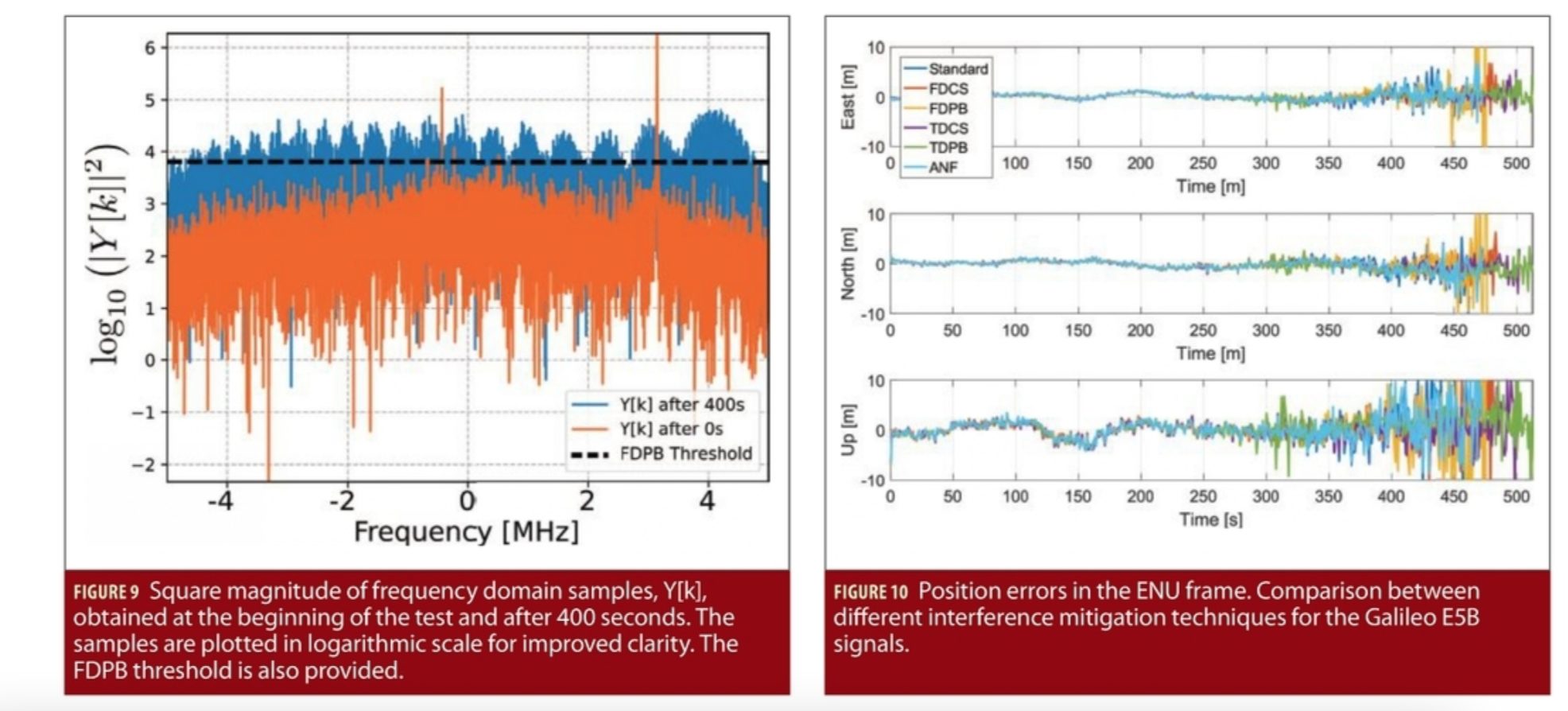
This choice has been dictated by the fact that, in the absence of interference, the samples, Y[k], should approximately follow a Gaussian distribution and, under this hypothesis, only few of them should assume values greater than 3 times their standard deviation. This choice is however too conservative for the specific jamming signal used in Test 1. This fact is analyzed in Figure 9 that shows the square magnitude of the frequency domain samples collected at the beginning of the test and after 400 seconds. The corresponding FDPB threshold is also provided. At the beginning of the test, a very limited number of peaks passes the FDPB threshold. The two main peaks passing the threshold correspond to the clock CWs that are correctly excised. After 400 seconds, the jamming signal is so strong that most of the samples pass the threshold leading to the removal of a significant portion of the useful signals as well.
This result shows the importance of properly selecting the domain of operations and the parameter settings of interference mitigation techniques. Parametric approaches such PB and frequency excision may be significantly influenced by the selection of the decision threshold. The ANF and FDCS do not significantly improve the receiver performance but do not suffer the degradations of FDPB.
Results similar to those shown in Figure 8 were obtained for the Galileo and Beidou signals in a single-constellation SPP solution. Also Test 2 led to similar findings and the interested reader is referred to our paper published in NAVIGATION.
Position errors obtained for the test conducted on the Galileo E5B signals are shown in Figure 10: also in this case all the techniques lead to time series with a consistent trend. The advantages of using a wideband signal such as the Galileo E5B component are also evident: the position errors are significantly lower in magnitude then those observed for the GPS L1 C/A modulation.
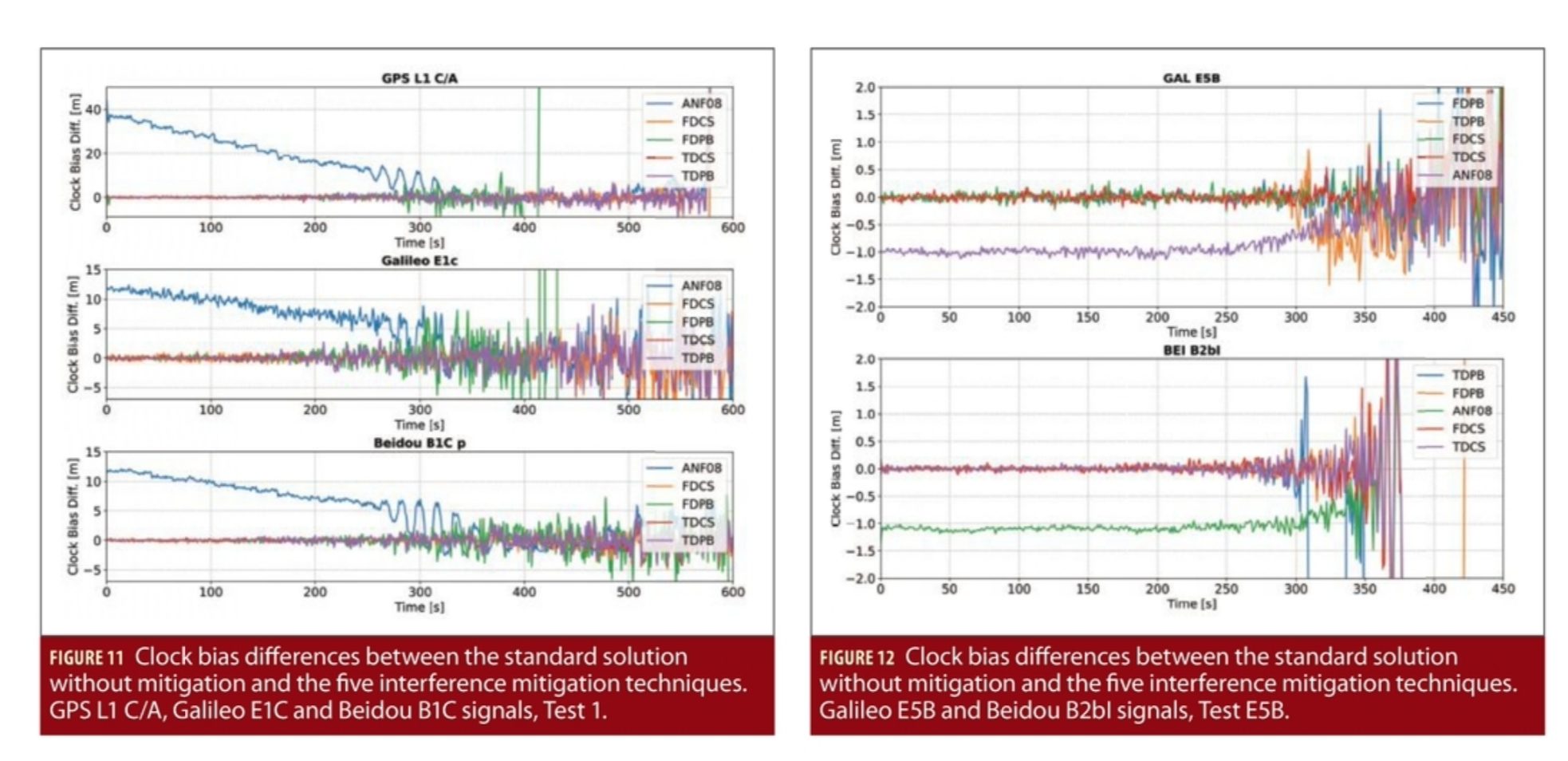
The impact of interference mitigation on the clock bias is analysed in Figure 11 and Figure 12 that consider Test 1 and Test E5B, respectively. As discussed above, the clock bias absorbs most of the delays introduced by the ANF on the pseudoranges. From Figure 11, a delay up to 35 metres is introduced by the ANF on the GPS L1 C/A clock term whereas a bias of about 12 metres is observed for both Galileo E1C and Beidou B1C solutions. The delay on the GPS L1 C/A solution corresponds to about 120 nanoseconds. Since the clock bias is used by timing receivers to steer the local time to the GPS/Universal Time Coordinated (UTC) time scales, the ANF can render timing solutions unsuitable for high-end timing applications. On the contrary, RIM techniques do not introduce biases and the corresponding time series in Figure 11 and Figure 12 are zero mean. The results on the clock bias confirm the fact that the ANF affects Galileo and Beidou signals, which share the same spectral characteristics, in the same way introducing a common delay.
Finally, Figure 12 further highlights the advantages of using wideband signals such as the Galileo E5B and Beidou B2bI components. The time series are less noisy than the ones obtained in Test 1. Moreover, the bias caused by the ANF is reduced to about a metre.
Conclusions
This article experimentally evaluated the impact of five interference mitigation techniques on pseudoranges and on the final position and timing solutions. The analysis included the ANF, time domain PB, frequency excision and two additional RIM techniques. Moreover, several GNSS modulations were considered from three GNSSs: GPS, Galileo and Beidou. From the analysis, it emerged that RIM techniques, including time domain PB and frequency excision, do not introduce biases at both measurement and position/clock level whereas the ANF delays pseudoranges. The delays are however common to all the measurements and only the clock component is affected in the final position solution. In this respect, delays of several tens of nanoseconds were observed. These delays, which are difficult to predict and depend on the jamming signal tracked by the ANF, are modulation dependent: signals sharing similar spectral characteristics are delayed in a similar way.
The analysis focused on a SPP solution and additional work is required to determine if a more evident effect could emerge in a Precise Point Positioning (PPP) framework. The analysis also confirmed that the domain of operation of RIM has to be carefully selected along with the parameters of the RIM non-linearity. In this respect, parameters improperly set can lead to performance degradations.
Manufacturers
The SDR front-end used for the experiments is an Ettus Universal Software Radio Platform 2 (USRP 2) device from Ettus Research, a National Instrument Brand, Santa Clara, California.
Additional Resources
(1) D. Borio and C. Gioia “Robust Interference Mitigation: a Measurement and Position Domain Assessment,” Proceedings of the 2020 International Technical Meeting of The Institute of Navigation, San Diego, California, January 2020, pp. 274-288.
(2) D. Borio and C. Gioia “GNSS Interference Mitigation: a Measurement and Position Domain Assessment” NAVIGATION, the Journal of the Institute of Navigation. Spring 2021; Vol. 68, Issue 1, pp. 93-114, https://onlinelibrary.wiley.com/doi/full/10.1002/navi.391.
(3) D. Borio and P. Closas “A Fresh Look at GNSS Anti-Jamming”, Inside GNSS, Volume 12, Number 6, September/October 2017, pp. 54-61.
(4) D. Borio and P. Closas “Robust Transform Domain Signal Processing for GNSS”. NAVIGATION, the Journal of the Institute of Navigation. Summer 2019; Vol. 66, Issue 2, pp. 305–323, https://onlinelibrary.wiley.com/doi/full/10.1002/navi.300.
Authors

Daniele Borio holds doctoral degree in electrical engineering from Politecnico di Torino in April 2008. He worked a senior research associate in the PLAN group of the University of Calgary and is currently a scientific policy officer at the Joint Research Centre of the European Commission (EC) in the fields of digital and wireless communications, location and navigation.

Ciro Gioia received a Ph.D. in navigation sciences from Parthenope University. After working as an external consultant at JRC, he is now scientific project officer at the JRC focusing on location and navigation.


