For driverless vehicles, current GNSS meter-level positioning accuracy still serves for lane-level detection. However, hazardous misleading information poses a serious, disruptive and critical safety concern.
GNSS is well-versed and well-used for vehicle in-dash navigation, where no catastrophe ensues if positioning is interrupted or wrong. Those days are soon over. Multiconstellation/ multi-frequency (MCMF) GNSS with protection limits and correction services are necessary to move forward safely.
This technology does not work off the small-size, single- frequency, narrow-band antennas that cars currently carry. Solutions in other sectors do not fit automotive market requirements.
NovAtel joined Inside GNSS to sponsor a webinar presenting experts in the automotive field with deep experience in automotive autonomy. They shared their research, solutions and insights.
Here’s what engineers must consider:
To use MCMF chipsets for safe and assured lane-level positioning, these factors should be taken into account:
- New patch or helix technology that covers multiple frequencies.
- The stability of the frequency response in those bands.
- Ground planes for the antennas to ensure the antenna can cover the large frequency range.
- Multipath effects.
- Doing all of this to automotive standards, in high volume, for low cost.
These experts understand the entire signal chain from antenna to receiver, to protection limits, and how everything works together.
Webinar panelists included:
Kevin Doherty, team lead, technical sales for NovAtel.
Curtis Hay, technical fellow at General Motors/OnStar. Kazuma Gunning, Ph.D. candidate in the GPS Research Laboratory of the Department of Aeronautics and Astronautics at Stanford University. They shared their expertise and answered live audience questions during the December 2019 webinar.
CHANGES ON THE ROAD
Kevin Doherty began the webinar by discussing the traditional application of GNSS in the automotive world: navigation to guide the driver from Point A to Point B. This doesn’t have a need for high precision, because the onus for the actual vehicle operation remains on the driver. These applications use simple algorithms based on pseudoranges, and don’t require any corrections services. They are singlefrequency, supporting L1.
The situation is now changing. Traditional antennas simply can’t keep up with trends toward autonomy in the automotive market. Automotive manufacturers are taking more controls out of the hands of the driver and putting it into the mind of the autonomous vehicle. Safety and efficiency require lane-level resolution, maximum availability, and assured reliability—guarantees that the positioning information can be trusted.
He continued with a specific set of metrics for the new antenna solution: it must be multi-frequency, it must be multi-constellation, and its phase center offset center variation must deliver unit-to-unit repeatability and multi-frequency coincidence; that is, how well reference points from L1 and L5, for example, overlap in the horizontal reference plane.
Phase center variation in the antenna will also affect the accuracy of delivered measurements.
He covered ground plane requirements for antenna installation and integration issues with the inertial sensor, and error factors that can be mitigated at the antenna level.
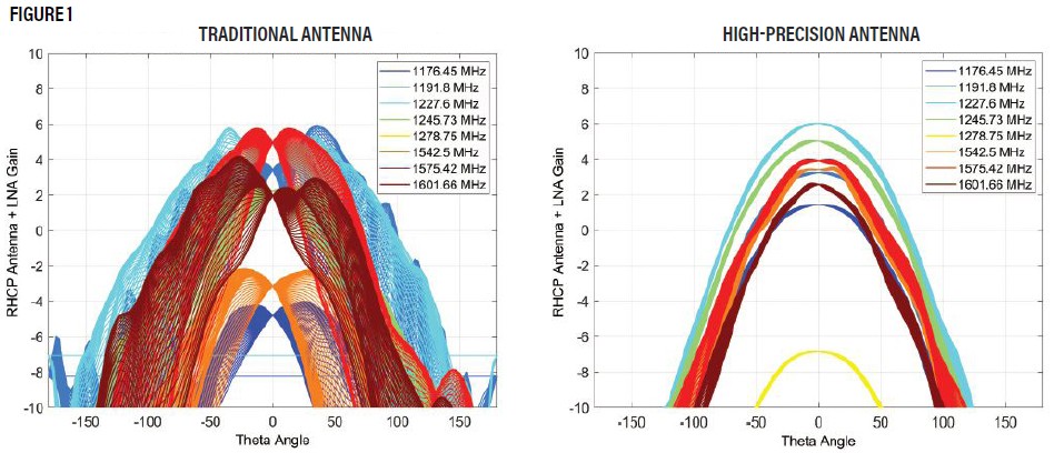
“An antenna designed for highprecision automotive applications produces a consistent gain pattern for all satellites across the sky, minimizing variability and helping to maintain tracking,” he explained, referring to the plot on the right in Figure 1. “In a traditional antenna, shown on the left, major inconsistencies in the pattern would lead to an inability to maintain lock while changing direction. We’ve actually seen this in some of our testing of traditional antennas, where a number of observations just dropped off while we were driving around a traffic circle.”
THE AUTOMAKER’S PERSPECTIVE
Curtis Hay from General Motors/ OnStar differentiated perception sensors and absolute vehicle localization sensors. The first group, consisting of radar, LiDAR and cameras, each bring distinct pros and cons.
Absolute localization (latitude, longitude, elevation and heading) as furnished by GNSS can be used for lane identification, to complement other sensors with redundancy, and as an enabler for high-definition map crowd-sourcing.
He considered several other influential factors, such as wireless connectivity, important for the delivery of GNSS corrections as well as map updates and traffic information, and practical considerations such as the real estate under the typical antenna sharkfin. With several different kinds of antenna housed inside, potential interference becomes just one of several design parameters to resolve.
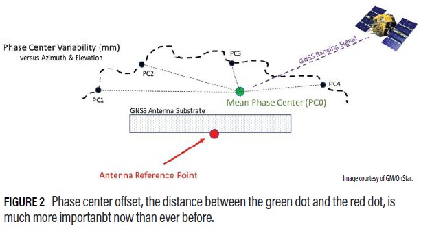
He then took a short deeper dive into the issues of phase center offset and phase center variability raised by Kevin Doherty: axial ratio, response, RF isolation, and more (Figure 2). He concluded with a short discussion of anti-jam.
UNDER OBSTRUCTION
Kaz Gunning from Stanford showed results from his research into positioning integrity for tightly coupled precise point positioning (PPP) and an inertial measurement unit (IMU). Antenna multipath rejection capabilities took center stage here, again with phase center offset and phase center variation playing key roles.
“Phase center offset is really important, especially when you have an IMU involved in your navigation solution because of the lever arm offset. This is the position delta between your IMU and the phase center of your GNSS antenna. Even small variations in those can introduce pretty big errors. It’s really important to keep the phase center offset stable from unit to unit so that you don’t have to calibrate for each antenna.”
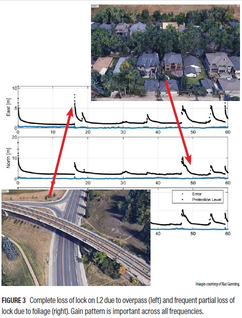
Gunning’s results (Figure 3) demonstrated how a receiver loses lock under a highway overpass and under suburban tree canopy. The blue line is the position error compared to a truth reference system onboard the vehicle, and the black is the protection level, the computed error balance.
To hear more, download the webinar at www.novatel.com/webinars.

 Workshop")

