The ability of a simulator to drive IMU interfaces correctly and precisely is vital to understanding, testing and validating GNSS/INS performance in high-end systems.
The development, refinement and evaluation of embedded GNSS/in- ertial navigation systems (EGIs) is a complex undertaking. GNSS/INS synchro- nization requires a precisely coordinated simulation of numerous navigation signals with a tightly coupled or ultra-tightly cou- pled GNSS/INS navigation system.
The ability of a simulator to drive IMU interfaces is often the differentiator to ef- fectively understanding, testing and vali- dating GNSS/INS performance in high-end systems.
THE CROQUET CHALLENGE
The quality of a strapdown IMU is defined by the accuracy of its gyroscopes and accelerometers as well as the signal pro- cessing pipeline and the minimization of errors such as bias errors, velocity errors, platform tilt, and errors induced by limited inertial sensor bandwidth.
While GNSS systems determine position from point to point, simulating an IMU for proper performance is analogous to hitting a croquet ball through wickets—it’s a steady and calculated bump along a path. John Clark, Vice President of Engineering at CAST Navigation, explains, “Hit too hard and you miss a wicket and head off in the wrong direction with no easy way to correct. To stimulate an IMU, you give it a starting location and you bump along with stimulus. You need to model the IMU correctly with considerations for GNSS coherence and for values such as coning, sculling and other error sources such as bias and individual sensor noise.”
Military and government labs have very strict requirements for dynamic ground testing of new navigation systems prior to flight testing. RF simulators can help recreate the conditions of a real flight. “With high-fidelity sensor error models, a simulator can include the addition of errors into the inertial stimulus thus allowing for a better overall system simulation allowing for realistic system performance measurements,” he adds.
REPLICATING REALISM
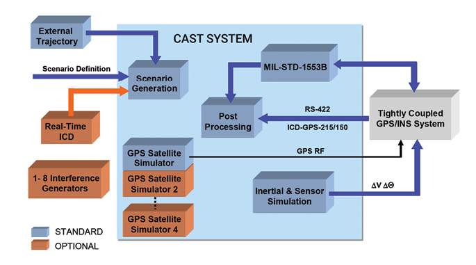
CAST Navigation’s INS Systems simulate dynamics for both the GNSS and INS por- tions of EGI and GNSS/INS systems in a coordinated and coherent way so that the GNSS and INS navigation solutions do not diverge and the solution precisely dupli- cates real world conditions (Figure 1).
While some simulators construct an INS error model and add its output to the true user state, CAST’s approach more closely imitates the operation of an INS. Essentially, the CAST INS Systems drive inertial measurements. Clark explains, “It electrically disconnects or puts the gyros and accelerometer to sleep and sends delta V and delta θ to a Kalman filter in order to test system dynamics. In this condition, the EGI can output raw IMU measure- ments to a receiver under test, which allows users to test GNSS receivers that are tightly integrated with a strapdown IMU.”
Initially, the CAST INS Systems simulate an ideal IMU by computing error-free inertial measurements using a complete whole-state model of the inertial system. Then the simulator adds errors to the measurements using detailed sensor error models and simulates the output of the IMU.
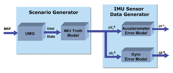
As shown in Figure 2, the user motion profile is defined by the MSF (Maneuver Segments File). The UMG (User Motion Generator) expands the maneuvers in the file into a trajectory (defined by the user state at various times). The IMU truth model uses the user state to compute error-free values of specific force and al- titude. The Sensor Data Generator then uses the gyro error model to compute error-free Delta θ measurements from changes in altitude. The accelerometer error model adds the error measurements to the ideal specific force measurements. Delta θB and Delta VB (relating to the ve- hicle body frame) are properly formatted, and output through the appropriate interface with the correct timing.
“The CAST INS Systems read the file, performs the necessary formatting, and outputs the measurements through the appropriate interface with the correct timing,” confirms Clark.
RELIABLE PERFORMANCE
As a leader in mixed-signal optics and Systron Donner Inertial MEMS-based products for aerospace and defense systems, EMCORE Corp. relies on GNSS/INS simulators for hardware-in-the-loop testing to verify the expected performance of algorithms.
Andy Williams, senior field applications engineer with EMCORE explains, “Few things can be as rewarding as a successful field test or as embarrassing and detrimental as a failed field test. Vetting the system as thoroughly as is reasonably possible is essential. Hardware-in-the-loop testing is a critical part of that vetting process.”
A proper evaluation of an GNSS/IMU device requires the IMU behavior to be accurately replicated and synchronized to the GNSS radio frequency (rf) for a given flight path, the CAST simulator provides error free IMU data to our GNSS/IMU data to our GNSS/IMU system,” he continues. “In real time, the GNSS/IMU system perturbs the data from the CAST simulator with data from the internal gyroscopes and accelerometers to replicate sensor imperfections. Simultaneously, the GNSS/IMU system receives from the CAST simulator GNSS rf that is synchronized to the error free IMU data. The GNSS receiver and navigation algorithms are tested over a variety of situations with relative ease and minimal cost.”
TACTICALLY SOUND THROUGH SIMULATION
In a recent study, EMCORE engineers sought to validate the velocity and altitude limits of a new GNSS receiver along with the algorithm performance in a tactical grade SDN500 system.
The test requires altitude over 24,000 meters and velocities over 600 m/s. Only a few aircraft in the world have such capabilities. While a test flight on an SR-71 Blackbird might be appealing to many, it isn’t practical. On the other hand, simulating the test flight with the CAST system is straightforward and cost-effective. The CAST GNSS/INS simulation generates GNSS and IMU signals corresponding to a user-defined flight trajectory.
The SDN500 receives the dynamic inertial data from the CAST simulator for the flight trajectory and combines that data with the imperfect inertial data from the IMU sensors. Simultaneously, the GNSS receiver in the SDN500 receives the synchronized GNSS rf from the CAST system. The SDN500 navigation processor uses the combined inertial data and the GNSS receiver output in the navigation algorithm to provide a navigation solution to the user.
The hardware-in-the-loop use of inertial data perturbed in real-time by the actual IMU sensors and the real-time data from the embedded GNSS receiver provides a more accurate representation of the SDN500 system performance than would otherwise be achieved by an equivalent pure software simulation.
The test began with a stationary period on the ground while the SDN500 initializes and transitions into air navigation mode. After the initial hold period, the flight trajectory entered a series of maneuvers that provided observability for various parameters with corresponding changes in the calculated figures of merit. The flight scenario then continued through a series of speed and altitude changes.
The dynamic constraints tested include:
• Max altitude of 24,000 meters
• Max velocity of 600 m/s
• COCOM combined altitude (18,000 m) and velocity (1000 knots/514 m/s) limits
A TRUE REFERENCE
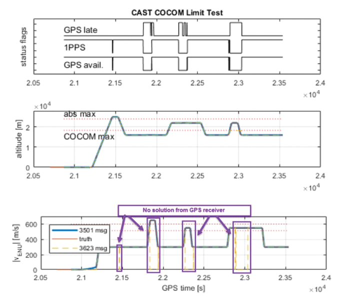
A sampling of the test results for the GNSS/INS simulation is shown in Figure 3, which begins with the ‘flight’ on the ground and climbing to an altitude of 25,000 meters (above the absolute max altitude defined by manufacturer=24,000 meters) and then dropping to an altitude of about 15,000 meters (graph 3b between 2.1-2.2).
The top graph (3a) plots the system status flags pertaining to GNSS availability to the SDN500. The second graph (3b) tracks the altitude throughout flight while the third graph (3c) shows the magnitude of velocity of the solution compared to truth reference system (solid orange line).
Throughout the test, the CAST simulation continues to test COCOM restrictions, initially with the sequence of altitude greater than 18,000 meters and then for a velocity exceeding 514 m/s. Notice both altitude and velocity must violate the respective limits before the GNSS receiver fails in order to provide the 1PPS and position/velocity solution. Next, the sequence is reversed with the velocity exceeding the COCOM limits first, followed by altitude. Critical to the test results is that the blue 3501 msg data (SDN500) and orange truth (CAST trajectory input) lines overlapped throughout even when there was no valid solution from the GNSS receiver.
Williams explains, “During the times when there was no valid solution from the GNSS receiver the algorithm maintained an accurate solution using only the data from the IMU. In addition, there was no algorithm instability or discontinuity when the GNSS receiver resumed, providing a solution to the algorithm. Throughout this entire profile, even when GNSS signal is lost, the SDN500 maintains an accurate navigation solution. This test is not possible without the synchronized GNSS rf and trajectory matching IMU data provided by the CAST system.”
Bottom line, the GNSS receiver and navigation algorithm was confirmed to operate as expected throughout the operation for all three of the dynamic constraint scenarios.
MANAGING INTERFERENCE
The CAST INS Systems simulator has the capability to interface with GNSS/INS navigation system under test in such a way as to record the navigation messages from the GNSS receiver that report jamming relevant values. Typically these messages include J/S ratios, satellite azimuth and elevation, and sometimes even individual satellite pseudoranges. By making these recordings available to users, the test report creation process is greatly simplified.
The CAST INS system can handle up to eight independently controlled jamming signals. Each generator can be assigned a speed, altitude, and trajectory profile. The jamming modes include Continuous Wave, Pulsed Continuous Wave, Swept Continuous Wave, FM Noise, Pulsed FM Noise, and Wideband Noise.
Properly simulating modern integrated navigation systems requires the ability to provide high rate inertial data with exceptional fidelity. CAST INS systems are equipped to test a wide variety of vehicle types including airborne, terrestrial, aquatic (including the sea-state) and space-based orbital vehicles for military, industrial, and commercial laboratory clients


