
Guest columnist Mark Looney on how enhanced performance has led MEMS IMUs to be key enablers for scalable AV platforms.
MARK LOONEY, APPLICATIONS ENGINEERING MANAGER, INERTIAL MEMS TECHNOLOGY GROUP, ANALOG DEVICES
GPS and Inertial sensing are key parts of Guidance Navigation Control (GNC) systems in emerging autonomous vehicles (AV). For position tracking and other sub-functions in the GNC, establishing a common time reference between GPS position updates and inertial measurement units (IMU) data sampling can be an important objective, especially in situations that value the tightest level of coupling between these two inertial tracking sub-system elements.
While this seems like a simple task, there are two important things to consider when seeking to synchronize these two sensing functions: (1) both systems tend to operate autonomously from one another and (2) some IMU-supported functions require much higher sample rates than those in GPS systems. GPS systems typically update at rates that are between 1 and 20Hz. IMU update rates are typically well beyond 1,000Hz.
The solution to the first challenge of synchronizing two “typically independent and autonomous functions” is establishing external control of data sampling as a requirement when selecting a MEMS IMU for the platform. Using the GPS clock and a phased locked loop function to scale up to a sample rate that supports all possible use cases for the IMU is the solution to the second problem.
Recently released IMUs contain functions that can address both challenges by including the clock scaling function inside the clock management function. Recognizing potential value for this type of synchronization can lead to a specific design requirement for connecting the GPS clock reference and the MEMS IMU, even in early prototyping. Establishing this connection will provide software developers with the option of using this feature when operational environments warrant such tight coupling while retaining the value of higher IMU sample rates.
MEMS Inertial Measurement Units
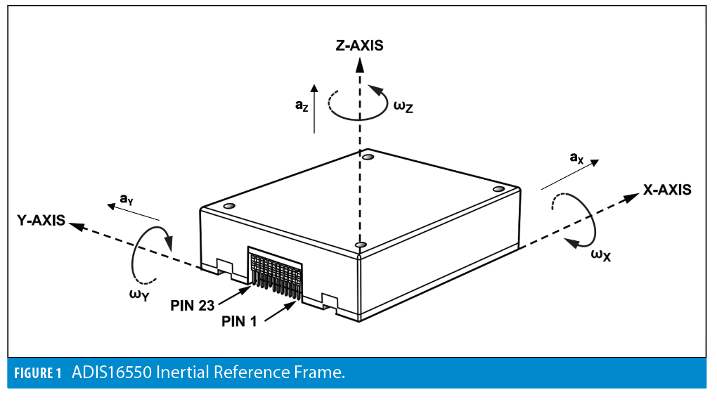
MEMS IMUs typically include triaxial angular rate (gyroscope) and linear accelerometer sensing functions. Figure 1 provides an example of MEMS IMU axial definitions, including the direction/polarity of each sensor [1]. When used in the GNC system for an AV platform, the Cartesian coordinate assignments from Figure 1 often translate into roll (X), pitch (Y) and yaw (Z) axial titles. MEMS IMU data sampling and processing rates are often driven by unexpected motion artifacts, such as vibration or underdamped mechanical response to bumps and abrupt changes in the terrain. Even in benign environments, such as a warehouse, under sampling the response of running over a small board or a tool left on the ground can lead to steering errors and require human-level intervention to restore full operation.
MEMS technology has always offered breakthrough levels of size, weight, power, cost, and ease of use but now is starting to reach performance levels that overlap with more contemporary technologies, such as Fiber Optic Gyroscopes (FOG). This performance enhancement is causing MEMS IMUs to be a key enabler for scalable AV platforms, such as local “last mile” delivery platforms.
Autonomous Ground Vehicles
The dull, the dirty, the dangerous. That has been the classic answer to the question, “What do autonomous vehicles do?” This description covers a wide range of missions in airborne, surface marine, submarine, and ground-based operating environments. For simplicity, let’s focus the rest of the discussion on a single platform type: autonomous ground vehicles (AGV) that will operate outdoors through complex terrain on dirt trails/roads. Perhaps ironically, AGV GNC platforms are still using many of the same functions published 10+ years ago, but with substantial advancement in all these functions. An outdoor cargo AGV may have any combination of the following functions: GPS, RTK, LiDAR, radar, wheel-based odometry, video, air speed and IMUs.
AGV Use Cases for IMU
Steering Feedback
The process of converting measured wheel speeds and direction into a steering solution is called reverse kinematics [2]. The precision of the reverse kinematics process relies on several factors, which are often difficult to control. Wheel diameter varies with tire pressure and temperature. Mechanical gear backlash can introduce asymmetry between forward and reverse motion on each wheel. In addition to the mechanical limitations of this system, wheel slippage also can introduce substantial errors in the steering feedback loop. This is especially true for platforms that are navigating over loose dirt surfaces and have time pressure that forces “best available” velocity. On an AGV, the MEMS IMU’s yaw (z) axis gyroscope often aligns with the primary steering axis, which allows the GNC system to track angular changes during commanded maneuvers. When operating in this manner, IMU sample rates are often much greater than the bandwidths of the steering feedback loop.
Terrain Compensation
GPS antennas must be on the top side of an AGV to have the best available access to GPS satellite-driven signals. When AGVs are navigating through complex terrains, the resultant roll and pitch angles (away from horizon) will cause alignment error between the GPS antenna and the steering references on the ground. Terrain compensation systems use both accelerometers and gyroscopes to track the attitude angles in real time so the GNC can correct the difference between the GPS location and the steering reference point on the vehicle.
Position/velocity tracking
Most outdoor platforms have regular access to GPS, but there are a number of use cases in which MEMS IMUs contribute to position and velocity tracking between GPS updates and partial GPS denial mitigation strategies. Strapdown navigation is one of the most common techniques for using MEMS IMUs to estimate velocity and position. The strapdown architecture uses gyroscopes to track and remove the gravity vector from the accelerometers so gravity will not contribute to the integration (velocity) and double integration (position) error growth models.
MEMS IMU Performance Advancement
Given the increasing dependence that AV platforms are placing on both short-term and long-term performance attributes, it is important to understand key performance attributes when developing selection criteria for the MEMS IMU. Since FOGs inspired the vision for early development of high-performance MEMS IMUs, Appendix C of IEEE-STD-975-1997 provided the basis for early definition of many MEMS IMUs performance attributes. As the vision for MEMS IMUs expanded out of automotive safety systems and into gaming and fitness tracking applications, there was extraordinary integration along with reduction in size, weight, power and cost. Because these applications focused on tracking simple, repetitive motion profiles, the most important performance attributes focused on short-term noise and stability attributes.
For example, Angle Random Walk (ARW) describes the rate of drift from integrating the random noise of a gyroscope, with respect to time. Rate Noise Density (RND) describes the magnitude of the noise in spectral terms for those trying to assess loop bandwidth for angular jitter contribution from the noise in their feedback loops. In-Run Bias Stability (IRBS) comes from the minima of the Allan Deviation curve and quantifies the best-available observability of bias error under static inertial conditions and benign environments.
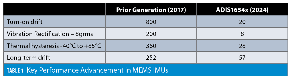
For AV platforms that have simple mission profiles and can afford the latency times associated with correction feedback that comes from other sensor platforms, these noise/stability metrics are the primary points of interest. When the mission profile has demanding inertial attributes, operates in challenging environments and the consequences of failure are elevated, GNC systems are sensitive to a much broader range of condition-dependent behaviors. Turn-on drift, Thermal hysteresis, long-term and vibration rejection are examples of these behaviors [3].
Turn-on drift typically comes from thermal settling but can have other contributors. This typically follows a first-order, decaying exponential, so the key attributes to understand are the initial error and the time constant. This error source typically has a deterministic model, but the key attributes are often dependent on both ambient temperature and proximity to thermal equilibrium. Thermal hysteresis is the difference between the sensor’s bias when moving up and down, in temperature. This attribute is dependent on thermal ramp rate and other mechanical stress attributes, which make it exceedingly difficult to model. Long-term aging typically comes from a combination of electrotonic drift and mechanical settling. The dependence on mechanical settling means thermal shock and other drastic changes in the force profile can change the drift model over time. The bottom line is this error window requires bias estimation loops to manage it. Finally, Vibration Rectification Error (VRE) is the most common metric for quantifying vibration rejection in both accelerometers and gyroscopes. This attribute typically impacts drones but can influence AGVs as well.
Table 1 shows an example of the type of advancements in MEMS IMUs over the past generation of devices [1]. The net result of these improvements is that in the most demanding environments, system algorithms can reduce latency and convergence times in the estimation loops, widening the conditions the platform can operate through.
MEMS IMU Operation
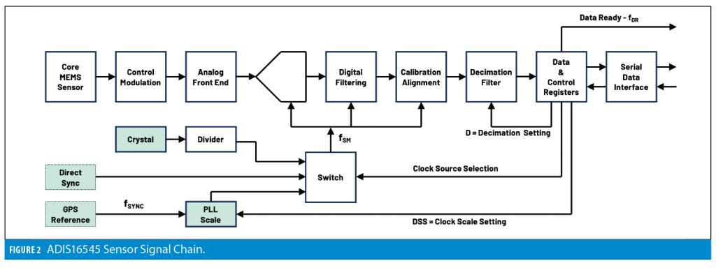
Modern MEMS IMUs, such as the ADIS16550, contain complete “motion to calibrated bits” signal chains that provide AV GNC systems with simple, configurable access to inertial sensing. They typically only need a decent power supply to self-initialize and begin producing quality data without requiring any external configuration. That data is available through communication channels that most embedded platforms support with minimal configuration. Figure 2 provides an example of a MEMS IMU functional block diagram.
MEMS sensors typically rely on tiny spring-tethered “proof masses,” which provide a center-tap for a differential capacitive network. When these devices experience acceleration, the proof mass sets back from the acceleration, causing a differential imbalance in the distances from each side of the fixed frame. In their simplest form, a modulation signal feeds through the center tap (proof mass) and through the capacitive path into two ends of the differential capacitor path. After demodulation, the residual signal represents the acceleration. For gyroscopes, the control and modulation schemes are a bit more complex, but for those that rely on the Coriolis acceleration, the net result is the same.
After demodulation, the residual acceleration (or angular rate) signal goes through an Analog Front End (AFE), which applies filtering to help manage noise and establish the desired sample rate to signal bandwidth ratios. The AFE also applies the signal to optimize the resolution of the digital portion of the signal chain for a given measurement range for each sensor.
Once the signals are through the analog to digital conversion process, they typically go through the primary digital filtering stage and then into the calibration and alignment process. On high-performance MEMS IMUs, calibration typically comes from an extensive inertial testing process, which observes bias, sensitivity (scale factor) and alignment at several different temperatures over the operating temperature. This information feeds into computation of sensor-specific, temperature-controlled correction polynomials for correction value, in the following calibration formula:
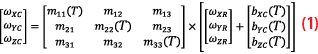
• ωXC, ωXC, and ωXC represents the calibrated gyroscopes for each axis.
• ωXR, ωXR, and ωXR represents the calibrated gyroscopes for each axis.
• bXC(T), bYC(T), and bZC(T) represent the bias correction function, which is typically temperature-dependent and can be implemented via look-up table or polynomial function.
• m11(T), m12, m13, m21, m22(T), m23, m31, m32 and m33(T) represent the sensitivity and alignment correction functions. The diagonal terms are typically temperature-dependent, while the off-diagonal terms are typically constant, with respect to temperature.
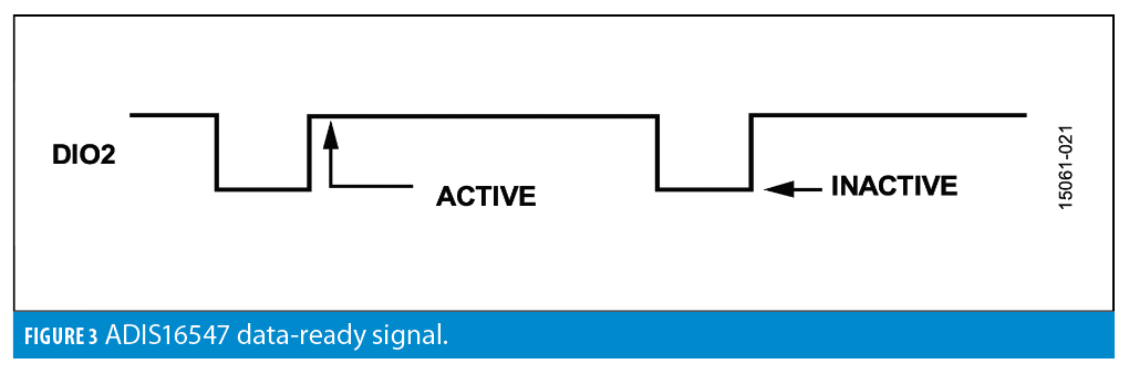
Finally, some IMUs provide a data-ready indicator function, which can help synchronize data collection and sampling in the GNC’s host processor. Figure 3 provides an example of such a signal, which pulses to an inactive state to indicate when the IMU’s processor is loading new data into the output registers. The inactive time provides a “do not access” time and the second edge of the pulse (inactive to active) can trigger the interrupt service routine (ISR) on the AGV GNC’s host processor.
IMU Data Synchronization
In addition to the basic signal flow, Figure 2 also shows three different options for driving data sampling and primary digital processing functions: Internal (crystal), Direct Sync and Scaled Sync (portrayed as GPS Reference). The internal clock source is the most common approach, as it enables fully
autonomous operation without requiring any external signals or commands to produce data. In the ADIS16547 IMUs the natural sample rate is 4,000Hz. This clock source comes from dividing the crystal frequency.
The Direct Sync functions allows an external clock source to drive the data sampling and processing. For optimal operation on the ADIS16547, the optimal external clock rate is 4,000Hz, but it will operate over a wider range of 3,000Hz to 4,500Hz.
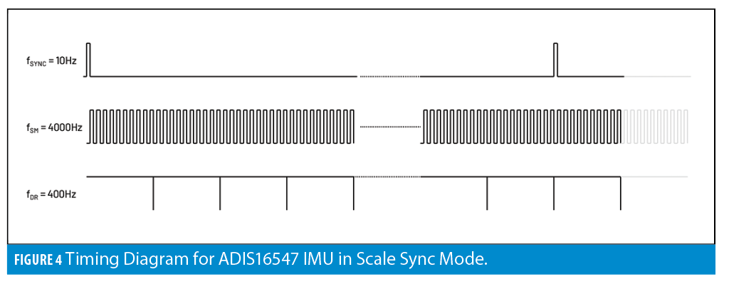
The Scale Sync function allows AGV GNC systems to provide a much slower clock reference (such as GPS or Video sync) while maintaining the optimal sample rate for the gyroscopes and accelerometers. Figure 4 provides an illustration for how this can work when feeding the ADIS16547 with a 10Hz reference signal from the GPS receiver. In this example, the GNC’s host processor will configure the ADIS16547 to operate in Scaled Sync mode and will configure the clock scale factor to 400 to cause the data sampling and processing to be at 4,000 Hz. This example also uses the decimation filter to average 10 samples (4,000Hz) together to produce each fresh data set for an output data rate (ODR) of 400Hz. This solves both problems of synchronization and reduces the output data rate to ease the processing burden on the GNC processor while retaining all the benefits of the higher sample rates in the initial stages of the IMU’s signal chain.
Conclusion
Given the performance advancement and functional integration, AV system architects are now able to reap the benefits of synchronizing MEMS IMU data sampling with GPS reference signals while retaining the benefits of sampling MEMS IMUs at higher sample rates. Having the flexibility to turn this connection on and off with simple register write cycles enables platforms to quickly transition to and from environments that deny GPS. In addition to software programmable switching between clock sources, programmable scale factors also enable quick reconfiguration when different GPS receivers are in use.
References
(1) Analog Devices Datasheet ADIS16550 Autonomous Grade, Six Degrees of Freedom Inertial Sensor, https://www.analog.com/media/en/technical-documentation/data-sheets/adis16550.pdf
(2) Looney, Mark, “Inertial Sensors Facilitate Autonomous Operation in Mobile Robots,” Analog Dialogue, 2010, vol. 44.
(3) I. Prikhodko, J. Geen, C. Merritt and S. Zhang, “Vibration Immune, Long-Term Stable and Low Noise Synchronized Mass MEMS Gyroscope,” 2021 IEEE International Symposium on Inertial Sensors and Systems (INERTIAL), Kailua-Kona, HI, USA, 2021, pp. 1-4
(4) Analog Devices Datasheet ADIS16547 Tactical Grade, Six Degrees of Freedom Inertial Sensors, https://www.analog.com/media/en/technicaldocumentation/data-sheets/adis16545-16547.pdf
Author
Mark Looney joined Analog Devices, Inc. in 1998 and is currently the Application Engineering Manager for the Inertial Sensing Technology Group. He earned Bachelor of Science (1994) and Master of Science (1995) degrees in Electrical Engineering from the University of Nevada. Since joining the industry in 1995, Mark has worked in development, characterization and system level integration of inertial sensing, high-speed analog-to-digital conversion, clock management, power management and embedded processing technologies. Prior to joining Analog Devices, Mark was a design engineer for the Interpoint Corporation and was a founding member of IMATS, a vehicle fleet and traffic solutions start-up company.


