 FIGURES 1, 2 & 3
For the complete story, including figures, graphs, and images, please download the PDF of the article, above.
In satellite navigation, a GNSS receiver must account for several sources of error such as relativistic effects, atmospheric propagation delay, offset of satellite clocks from system time and satellite ephemeris. In order to accurately compute user position, velocity, and time (PVT), these errors need to be predicted/estimated precisely.
The navigation signals transmitted on each carrier frequency are imperfectly synchronized due to different hardware paths corresponding to each signal. Each satellite’s navigation message contains parameters describing the timing bias. A user receiver uses these parameters to compute the clock correction for each observation.
Dual-frequency receivers directly employ such corrections. However, before a single frequency receiver can use the computed offset, it must be adjusted to account for the differential group delay between the principal signal and the signal on the other frequency. This timing group delay, annotated as TGD, results from hardware differences in the onboard signal paths and will vary among satellites.
The dual-frequency signal timing difference is used to infer the line-of-sight delay caused by the ionosphere, subject to the bias difference between the satellite transmissions at the two frequencies. Recently, the satellite navigation community has improved the inter-frequency/signal correction values contained in navigation messages.
This article will describe the timing group delays anticipated in the Indian Regional Navigation Satellite System (IRNSS) and the inter-signal delay correction (ISC) parameters that will be included in the navigation messages in order to improve the system’s PVT accuracy.
GNSS Service Regions
In the future, GNSS systems will have two types of service regions: a terrestrial service volume (TSV) and a space service volume (SSV). The IRNSS ISCs will take into consideration signal differences as they appear in these service regions.
We can characterize the TSV as a shell that begins at the surface of the earth and extends up to an altitude of 3,000 kilometers. The transmitted position-determination parameters are valid for the entire region, ensuring similar performance for all users within it. Users operating in the TSV have coverage from the main beams of the satellites.
The SSV is a shell extending from 3,000-kilometers to approximately the geostationary altitude, that is, around 36,000 kilometers. The SSV is further subdivided into two regions: from 3,000 to 8000 kilometers, and from 8,000 to 36,000 kilometers.
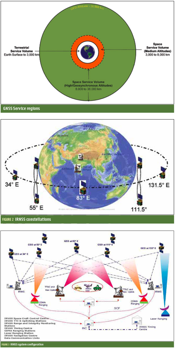
Space users (SU) will have varying levels of performance depending on the altitude. Within the SSV, nearly all navigation signals emanate from satellites across the limb of the Earth. Users within this region may experience periods during which no navigation satellite signals are available and, when they are, received power levels will be weaker than for the terrestrial users (TU). Timing correction for space users need to be provided. Figure 1 (above right) shows the shells of the various service regions.
IRNSS
The Indian Regional Navigation Satellite System envisages establishment of a constellation made up of a combination of geostationary Earth orbit (GEO) and geosynchronous orbit (GSO) spacecraft over the Indian region.
The IRNSS constellation will consist of seven satellites —three in GEO orbit (at 34º E, 83º E and 131.5º E) and four in GSO orbit inclined at 29 degrees to the equatorial plane with their longitude crossings at 55º E and 111.5º E (two in each plane) as shown in Figure 2. All the satellites will be continuously visible in the Indian region for 24 hours a day.
Figure 3 shows a detailed diagram of the IRNSS system configuration.
The IRNSS is expected to provide position accuracy (two sigma) of better than 20 meters over India and a region extending outside the landmass to about 1,500 kilometers. The system will provide two types of services, a Standard Positioning Service hereafter referred to as SPS, and a Restricted/Authorized Service or RS. Both of these services will be provided at two frequencies, one in the L5 band and the other in S-band.
. . .
Timing Group Delay
The time of radiation of the navigation signals on each carrier frequency and among frequencies is not synchronized due to the different digital and analog signal paths that each signal must travel from the IRNSS satellite signal generator to the transmit antenna. This hardware group delay is defined as a time difference between the transmitted RF signal (measured at the phase center of a transmitting antenna) and the signal at the output of the onboard frequency source.
Three different parameters comprise this group delay: a fixed/bias group delay, a differential group delay and a group delay uncertainty in bias and differential value.
. . .
IRNSS Group Delay Parameters
The uploaded data and the onboard-generated data will be formatted in a specific IRNSS format. As code, data, sub-frames, and main frame are synchronized to the space vehicle (SV) time (tSV), the principal code (RS) epoch is used to generate SV time.
The SV time is measured relative to the leading edge of the first chip of the first code sequence of the first frame symbol and represents the time of transmission of the signal from the satellite. The reference of transmission of signals is the antenna phase center. But, as mentioned earlier, a time delay occurs in the navigation payload between the time of signal generation and its actual time of transmission from the antenna array…
- Estimated Differential Group Delay.
- Group Delay Differential Correction.
. . .
IRNSS Group Delay Correction Algorithm
GNSS receivers designed to process IRNSS signals should account for the group delays, depending on the specific signals used and the service region in which they will operate.
- Single Frequency S-RS and L5-RS Users.
- Single Frequency S-SPS and L5-SPS Users.
- Corrected Pseudo Range For Dual Frequency Users.
. . .
Conclusion
The IRNSS signal structure has one group delay differential correction parameter (TGD). TGD is to correct for S- and L5- band RS signal group delays. To obtain better position accuracy, other single-frequency users require inter-signal group delay correction parameters (ISCL5-SPS, ISCS-SPS). For space navigation users with off-nadir angles greater than 8.4 degrees with respect to an IRNSS satellite, an SUD correction is required. The SUD bias will provide additional improvement on the order of three nanoseconds to space users. These will be transmitted in navigation data in the future.
For the complete story, including figures, graphs, and images, please download the PDF of the article, above.
Acknowledgments
The authors would like to express their sincere gratitude to Dr K.S. Dasgupta, deputy director of the SATCOM and Navigation Payload Area, Space Applications Centre‑ Indian Space Research Organization (SAC-ISRO), for his valuable guidance and encouragement during this study.
Additional Resources
[1] Hegarty, C., “Accounting for Timing Biases between GPS. Modernized GPS, And Galileo Signals,” 36th Annual Precise Time and Time Interval Meeting, Washington, D.C., December 2004
[2] Parkinson, B. W., and J. J. Spilker Jr., “Global Positioning System: Theory and Applications,” Volume I, Bradford W. Parkinson and James J. Spilker Jr.
[3] Tetewsky, A., and J. Ross, A. Soltz, N. Vaughn, J. Anszperger, C. O’Brien, D. Graham, D. Craig, and J. Lozow, “Making Sense of Inter-Signal corrections: Accounting for GPS Satellite Calibration Parameters in Legacy and Modernized Ionosphere Correction Algorithms,” Inside GNSS, July/August 2009
[4] U.S. Air Force, GPS Directorate, “Interface Specification IS-GPS-200,” Revision D, IRN-200D-001, March 2006
[5] U.S. Air Force, GPS Directorate, IS-GPS-800, Navstar GPS Space Segment/User Segment L1C Interface, August 2007, U.S. Air Force, GPS Directorate
[6] U.S. Air Force, GPS Directorate, Signal in Space Interface Control Document OS SIS ICD, Draft 1, GPS ICD, February 2008
[7] Wilson B., and C. Yinger, W. Feess, and C. Shank, “New and Improved: The Broadcast Interfrequency Biases,” Brian D. Wilson, Colleen H. Yinger and Willian A. Feess, Captain Chris Shank, GPS World, September 1999


