Working Papers explore the technical and scientific themes that underpin GNSS programs and applications. This regular column is coordinated by Prof. Dr.-Ing. Günter Hein, head of Europe’s Galileo Operations and Evolution.
Working Papers explore the technical and scientific themes that underpin GNSS programs and applications. This regular column is coordinated by Prof. Dr.-Ing. Günter Hein, head of Europe’s Galileo Operations and Evolution.
Modern global navigation satellite systems have adopted binary offset carrier (BOC) modulations to increase radio frequency (RF) compatibility among different signals and to improve ranging accuracy. BOC modulations use an additional signal component, the subcarrier, to move the signal power away from the signal center frequency and to obtain two main lobes displaced by fsub, the subcarrier repetition frequency.
The subcarrier significantly reduces interference issues and leads to signals with sharp autocorrelation functions, i.e., with improved ranging capabilities. BOC signals are, however, characterized by multi-peaked correlation functions, and, as a result, secondary peak lock can occur. Thus, several techniques have been designed to avoid secondary peak lock and to track unambiguously the main signal correlation peak. The design of unambiguous BOC tracking algorithms has been strongly influenced by the perception of the subcarrier, which evolved significantly over the last two decades.
This article will first review the various perceptions of the BOC subcarrier and then describe a new view of the subcarrier along with an advanced tracking algorithm that exploits this subcarrier concept to fully benefit from the structure of BOC modulated signals.
Subcarrier Perception
Modern GNSS signals can be modeled as the product of four components:
where
x(t) = d(t)c(t)sb(t)cos(2πfRFt) (1)
- d(t) is the navigation message containing the ephemerides and other navigation parameters
- c(t) is a pseudorandom sequence selected from a family of quasi-orthogonal codes. c(t) is binary phase shift keying (BPSK)–modulated, i.e., each element of the code is represented as a constant (positive or negative) value.
- sb(t) is the subcarrier obtained by periodically repeating a basic waveform
- the cosine term is the carrier which is used to up-convert the signal to the RF, fRF.
Figure 1 provides a schematic representation of the various signal components. (The figure ignores the navigation message, which slowly varies over time).
The code and carrier components are also present in legacy GPS signals and are usually processed using dedicated tracking loops: the delay lock loop (DLL) and the phase lock loop (PLL). The subcarrier has been introduced with the advent of Galileo (e.g., Open Service signal) and the modernization of GPS (e.g., L-band civil signal, L1C) to improve RF compatibility among different GNSS signals and increase ranging accuracy. (See the article by J. W. Betz, referenced in the Additional Resources section near the end of this article.)
The subcarrier has been considered in various ways by researchers and GNSS receiver designers, and its perception has been progressively changing over time. The subcarrier has been originally recognized as part of the ranging code, c(t), and jointly processed with it using a modified DLL. When considered in this way, the subcarrier modifies the code correlation function by leading to a narrower main correlation peak and by introducing secondary peaks.
Secondary peaks can be the source of ambiguity, and a standard DLL can erroneously lock on them, leading to biased pseudorange measurements. For this reason, one class of BOC tracking algorithms aimed to remove such ambiguity, for example, by introducing sentinel correlators as in the “Bump Jump” method detailed in the paper by P. Fine and W. Wilson, cited in Additional Resources. The sentinel correlators are used to verify that the peak locked by the DLL is the main one.
The subcarrier was then perceived as a nuisance component to be removed. In order to remove the subcarrier, several techniques were suggested such as the “SubCarrier Cancellation (SCC)” method described by P. Ward et alia (Additional Resources), side-band processing, and subcarrier pre-filtering. Although subcarrier removal can lead to robust signal tracking, the advantages brought by the subcarrier are generally lost in the process. In particular, these techniques usually lead to losses in terms of measurements accuracy, as they are unable to obtain code correlation functions with a narrow peak.
A new view of the subcarrier implies that the subcarrier should be considered similarly to the signal code and carrier in which a dedicated tracking loop is allocated to each component, including the subcarrier. Moreover, this approach suggests that the subcarrier should be exploited as a source of measurements in the same way as the code is used to generate pseudoranges and the carrier to produce carrier phase observations. For this reason, the subcarrier would also be used to generate subcarrier phase/delay measurements. Further, the subcarrier has characteristics intermediate between the code and carrier and, thus, can be processed by modifying techniques originally designed for these two signal components.
A fundamental step towards such a concept of the subcarrier was the “Double Estimator (DE)” suggested by M.S. Hodgart et alia (in this article) where the code and subcarrier are processed independently. In particular, the subcarrier is processed similarly to the code using a dedicated loop, the “Subcarrier Lock Loop” (SLL).
This method introduces subcarrier “Early” and “Late” correlators and uses these to track the subcarrier component. Moreover, this approach employs the concept of “subcarrier delay,” but only for tracking purposes. The subcarrier is not used for generating measurements, and code and subcarrier delays are recombined in order to generate pseudorange observations.
The DE method assimilates the subcarrier to an additional code superimposed through a multiplication of the BPSK-modulated ranging code. At the same time, a progressive understanding has emerged that the subcarrier is also similar to the carrier component. In the SCC method, two orthogonal sine waves are used as local subcarriers for the removal of the subcarrier component. In his Ph.D. thesis (see Additional Resources), C. Palestini used the subcarrier delay to smooth code measurements using a Hatch filter. J. Wendel and S. Hager (cited in Addition Resources) solved the subcarrier ambiguity problem using the LAMBDA method. These are approaches typically adopted for processing carrier phase measurements. The subcarrier is thus implicitly recognized as a source of measurements.
The “Double Phase Estimator (DPE)” described in the next section exploits this new conception of the subcarrier, which is approximated as a pure sinusoid and processed using a modified PLL, the “Subcarrier Phase Lock Loop (SPLL).”
The Double Phase Estimator
The DPE exploits the commonalities between carrier and subcarrier. Moreover, it takes into account the effects of the receiver front-end. In particular, Equation (1) models the transmitted GNSS signal but does not consider several propagation and reception effects, such as those caused by the receiver front-end.
In an article from the author listed in Additional Resources, it is shown that, in the presence of front-end filtering, the subcarrier of the received signal can be effectively approximated as a pure sinusoid. When assimilated as a pure sinusoid, the subcarrier can then be tracked using a modified PLL, the SPLL, which exploits the correlation of the input signal with two orthogonal local sinusoids.
Figure 2 provides a schematic representation of the DPE. The signal at the input of the DPE is denoted by y[n]. Note that y[n] is a digital sequence obtained by sampling a filtered and down-converted version of the signal recovered by the receiver antenna. The residual signal Doppler effect is at first removed using the complex exponential generated by the PLL used to track the signal carrier. Code and subcarrier components are then processed independently using a standard DLL and a SPLL, respectively.
The SPLL uses an additional correlator, denoted as quadrature prompt correlator, to estimate the residual subcarrier phase error. This correlator is obtained by correlating the input signal with a local replica orthogonal to the input signal subcarrier. This orthogonal subcarrier is obtained by delaying by Tsub/4 the standard subcarrier used for the evaluation of the standard prompt correlator.
Equation (a) (see inset photo, above right, for equations)
is the subcarrier period.
In Figure 2, the standard subcarrier appears as a sine wave, whereas the orthogonal subcarrier is a cosine wave. This choice is dictated by the fact that a sine-phased BOC modulation is considered in Figure 2. When a cosine-phased modulation is processed, cosine and sine waves should be adopted for the generation of standard and quadrature components, respectively.
In Figure 2, the symbol N represents the number of samples used for the signal correlation, and Fc(z) and Fsb(z) denote the transfer functions of the filters adopted by the DLL and the SPLL, respectively. In equations (2) and (3), the symbols P and PQ are used to denote the standard and quadrature prompt correlators. Two subcarrier discriminators can be used to extract the residual subcarrier delay error, as follows:
Equation (2)
Equation (3)
Discriminator (2) is sensitive to residual phase errors from the PLL whereas (3) is non-coherent and can operate in the presence of residual phase errors. Δτs is the residual subcarrier delay error, which leads to the discriminator outputs, εc and εnc, used to drive the SPLL.
Performance Analysis
In the DPE, the local subcarrier is a pure sinusoid. When a wideband front-end is used, the subcarrier of the received signal can be effectively approximated as a square wave. Under these conditions, a mismatch between received and local subcarrier could occur, which can introduce a signal-to-noise ratio (SNR) loss. In the worst case, this loss is equal to
Equation (4)
The SNR considered here is the coherent output SNR evaluated at the output of the prompt correlator. This SNR loss is present only in the absence of front-end filtering. An expression for the SNR loss (L0) can be found in the article by author cited in Additional Resources. L0 can become a gain when the signal is heavily filtered and the subcarrier of the received signal is more similar to a pure sinusoid than to an ideal square wave.
This fact clearly emerges in Figure 3 where the SNR loss is shown as a function of the front-end bandwidth. More specifically, a 9th-order Butterworth filter was used to simulate the effects of front-end filtering, and L0 was evaluated as a function of its cut-off frequency. Figure 3 considers the cases of sine BOC(1, 1) and cosine BOC(15, 2.5) and reveals that the DPE provides a gain for the processing of wide-band BOC–modulated signals. This is the case of the cosine BOC(15, 2.5) modulation adopted for the Galileo Public Regulated Service (PRS) signal: a front-end with a total bandwidth greater than 45 megahertz is required to obtain an actual loss.
Note that signal band-limiting can also be introduced on the transmitter side. For example, the cosine BOC(15, 2.5) transmitted by the GIOVE-B satellite was characterized by a bandwidth of about 40 megahertz. In this case, the DPE will always provide better performance with respect to standard techniques.
The use of pure sinusoids as local subcarriers also affects the correlation functions evaluated by the receiver. In particular, in the DE and in the DPE techniques, a two-dimensional crosscorrelation function is obtained:
Equation (5)
Note that these two components are delayed independently by τc and τs, the code and subcarrier delays tested by the receiver. The symbol ‘-’ has been introduced on the local subcarrier to indicate that a sequence different from the signal subcarrier, sb(•), can be used for the computation of cross-correlation (5). The DE uses a subcarrier equal to that of the input signal, whereas the DE uses sinusoidal subcarriers.
From the two-dimensional cross-correlation, it is possible to extract the following:
- the code correlation, when the subcarrier delay, τs, is matched to that of the incoming signal y[n]
- the subcarrier correlation, when the code delay, τc, is matched to that of the incoming signal y[n]
- the composite correlation, when the code and subcarrier delays are constrained to be equal, τc = τs. This is the correlation obtained by standard BOC tracking algorithms.
The following discussion only considers the subcarrier and composite correlations.
When a wideband front-end is used, the DE and standard BOC tracking algorithms are able to obtain sharp cross-correlation functions close to the “Ideal” curves depicted in Figure 4. In the presence of front-end filtering, the correlation functions obtained using square waves as local subcarrier are strongly impacted. This fact clearly emerges from Figure 4, which shows in the top and bottom panels, respectively, the composite and subcarrier correlation functions of a cosine BOC(15, 2.5) signal in the presence of front-end filtering. Signal band-limiting has been simulated by filtering the input signal with a 9th-order Butterworth filter and cut-off frequency f0 = 40 MHz.
In Figure 4, the curves denoted as “Ideal” and “Sin” are those obtained for the DE (square subcarrier wave) and for the DPE in the absence of filtering. When filtering is simulated, the correlation function computed using standard techniques are smoothed (“Filtered” curves in Figure 4). No significant difference can be observed for the DPE: Because only the first frequency component is retained, signal band-limiting has almost no effect on the correlation process, which implicitly performs filtering. The bottom part of Figure 4 reveals that when the front-end filter preserves only the main signal component, the DE and DPE operate on equivalent subcarrier correlation functions, which can be effectively modelled as pure cosine waves.
Tracking Jitter
The tracking jitter is a measure of the uncertainty of the final output provided by a tracking loop. The following discussion analyzes and compares the tracking jitter of the SPLL used in the DPE with that of the SLL of the DE. In particular, the tracking jitter can be computed as (see the book chapter by A. J. Van Dierendonck, Additional Resources):
Equation (6)
where σd is the standard deviation of the discriminator output, Beq is the loop equivalent bandwidth, and Tc = NTs is the coherent integration time. Gd is the discriminator gain defined as
Equation (7)
where S(τ) is the discriminator input-output function. S(τ) depends on the type of discriminator and can be computed using definitions (2) and (3).
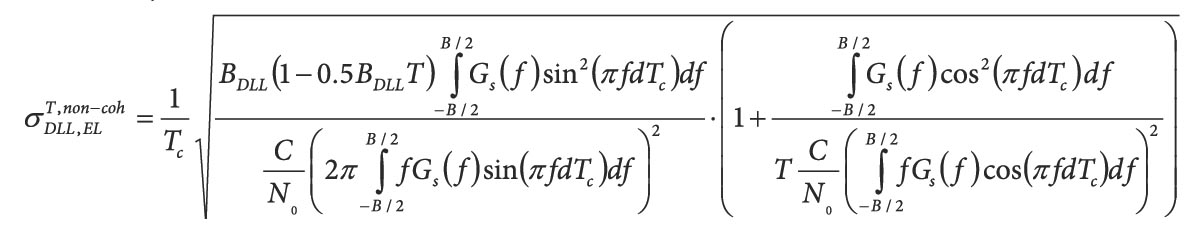
The 2014 article by the author shows that the following equation gives the tracking jitter of the SPLL, for both coherent and non-coherent discriminators:
Equation (8)
The last approximation in (8) was obtained by exploiting the hypothesis that the front-end bandwidth is approximately equal to half the sampling frequency, as follows:
Equation (9)
The tracking jitter of the output of the SLL used by the DE is given by
Equation (10)
and depends on ds, the subcarrier Early-minus-Late chip spacing. As previously mentioned, the DE treats the subcarrier similarly to the code, and two additional subcarrier correlators are used to track the main peak of the subcarrier correlation function. In Equation (10), ds is normalized by the subcarrier period, Tsub, and thus is unitless.
Figure 5 compares the tracking jitter of the SLL with that of the SPLL. The curves shown in the figure were obtained using the parameters listed in Table 1.
The performance of the SLL strongly depends on the Early-minus-Late spacing adopted: for narrow ds, the SLL outperforms the SPLL, which becomes preferable for ds greater than 0.25. For ds = 0.25, the SLL and SPLL have similar performance as predicted by (8) and (10) when
Equation (b)
The curves in Figure 5 were obtained in the least favorable case for the SPLL, i.e., in the absence of front-end filtering.
Figure 5 also provides the tracking jitter of the DLL of the SCC technique. Note that when recombining subcarrier and code measurements as in the DE, the dominant source of error stems from the SLL. Thus, we can effectively approximate the final tracking jitter using the subcarrier delay estimate. For this reason, the tracking jitter of the SCC can be compared with that of the SLL and SPLL.
Because no theoretical results are currently available for the SCC tracking jitter, Figure 5 only presents simulation results. The algorithm detailed in the article by P. Ward et alia was implemented and used for the analysis: Subcarrier Cancellation also requires the computation of Early and Late correlators for the DLL and the performance of the loop strongly depends on the Early-minus-Late chip spacing, ds, of these two correlators.
The results provided in Figure 5 indicate that the SCC is always outperformed by the other techniques. This anticipated outcome is due to the subcarrier removal operated by the SCC technique. Although the SCC uses a sinusoidal representation of the subcarrier, its performance is significantly worse than that of the DPE.
Real Data Processing
In order to test the effectiveness of the DPE, cosine BOC(15, 2.5) signals collected from the GIOVE-B satellite were used. Note that the European Space Agency decommissioned GIOVE-B satellite in July 2012 and that the dataset used in this paper was collected on November 5, 2011. The use of such a dataset is justified by the fact that it contains valid cosine BOC(15, 2.5) data with a known pseudorandom noise (PRN) code. Thus, the use of this dataset allows one to test the DPE for both the sine BOC(1, 1) and cosine BOC(15, 2.5) modulation broadcast in the Galileo E1 band. The cosine BOC(15, 2.5) signals transmitted by the currently operating Galileo satellites are encrypted, and use of them requires codeless techniques.
A complete analysis of the tracking results obtained for the sine BOC(1, 1) signal can be found in the article from the author listed in Additional Resources. The following discussion addresses only the case of the cosine BOC(15, 2.5) modulation. In particular, the DPE is able to effectively process the E1a signal. Figure 6 provides sample results including several metrics that indicate the proper functioning of the proposed technique. Table 2 lists the parameters used for the processing of the GIOVE-B E1a signal.
Figure 6a shows the amplitudes of the Prompt, Early, and Late correlators used by the DLL, coupled with the SPLL: After an initial transient period, the amplitude of the Prompt correlator is maximized whereas Early and Late correlators assume similar magnitudes.
Figure 6b provides the filter outputs of the three loops used for signal tracking. Each output is normalized by the fundamental frequency of the component tracked: the carrier Doppler by the GPS L1 center frequency, 1575.42 MHz; the DLL filter output by the nominal code rate, 2.5575 megahertz; and the SPLL filter output by the subcarrier rate, 15.345 megahertz.
The normalized filter outputs assume similar values indicating the possibility of carrier aiding: The normalized carrier Doppler can be used to help process the code and subcarrier components. As expected the code estimates are the nosiest. After about two seconds, the secondary code on the E1a signal is recovered and bit synchronization is achieved. Thus, the integration time is increased from 2 to 10 milliseconds.
The latter effect can be clearly seen in the code rate estimates in Figure 6b and in Figure 6c, which shows the in-phase and quadrature components of the E1a Prompt correlators. After bit synchronization, the secondary code is removed and the navigation bits can be extracted from the in-phase components of the Prompt correlator.
Finally, Figure 6d compares the magnitude of the PQ correlator with that of the Prompt correlator. After an initial transient, the magnitude of PQ is minimized and all the signal energy is concentrated in the Prompt correlator. This shows the ability of the Double Phase Estimator to properly track the different components of the cosine BOC(15, 2.5) modulation.
Conclusions
In this article, various ways of considering the subcarrier component have been briefly reviewed. In particular, the discussion promotes the idea that the subcarrier has its own “dignity.” In this respect, the subcarrier should be processed using a dedicated tracking loop and considered as a source of measurements.
Furthermore, the subcarrier has characteristics intermediate between the code and carrier, and thus it can be processed adapting algorithms originally designed for these two signal components. The Double Phase Estimator exploits the “carrier” nature of the subcarrier, which is processed using a modified PLL, the SPLL. The DPE is an effective alternative to the DE and can achieve improved performance in the presence of front-end filtering.
Additional Resources
[1] Betz, J.W., “Binary offset carrier modulations for radionavigation,” NAVIGATION, the Journal of the Institute of Navigation, Vol. 48, No. 4, pp. 227–246, Winter 2001
[2] Borio D., “Double phase estimator: a new unambiguous binary offset carrier tracking algorithm,” IET Radar, Sonar & Navigation, vol. 8, no. 7, pp. 729–741, August 2014
[3] Fine, P., and W. Wilson, “Tracking algorithm for GPS offset carrier signal”,” Proceedings of the National Technical Meeting of the Institute of Navigation (ION NTM 1999), San Diego, CA, pp. 671–676, January 1999
[4] Hodgart, M.S., and P. Blunt and M. Unwin, “Double estimator – a New Receiver Principle for Tracking BOC signals,” Inside GNSS, Vol. 3, No. 4, pp. 26-36, Spring 2008
[5] Palestini, C., “Synchronization and Detection Techniques for Navigation and Communication Systems”, Ph.D. thesis, University of Bologna, March 2010
[6] Van Dierendonck, A. J., “GPS receivers,” in B. W. Parkinson and J. J. Spilker Jr. (editors), Global Positioning System Theory and Applications, Chapter 5, Volume 1, pp. 329–407, American Institute of Aeronautics & Astronautics 1996
[7] Ward, P. W., and W. E. Lillo, “Ambiguity Removal Method for Any GNSS Binary Offset Carrier (BOC) Modulation,” Proceedings of the International Technical Meeting of The Institute of Navigation (ION ITM 2009), pp. 406–419, Anaheim, California, January 2009
[8] Wendel, J., and S. Hager, “A robust technique for unambiguous BOC tracking”, Proceedings of the 26th International Technical Meeting of the Satellite Division of The Institute of Navigation (ION GNSS+), Nashville, TN, pp. 1–12, September 2013


