Using atmospheric polarization for GPS-denied navigation
DR. LAURA ESHLEMAN, POLARIS SENSOR TECHNOLOGIES
The Sky Position and Azimuth Sensing System, SkyPASS, is a celestial-based sensor that uses three celestial navigation techniques to calculate absolute position and highly accurate attitude information regardless of GPS accessibility. SkyPASS has three separate optical channels for imaging the sun (or moon), sky polarization and stars. This article focuses on how SkyPASS exploits atmospheric polarization to find North and absolute position in GPS-denied environments.
SkyPASS Overview
SkyPASS [1] was initially designed as a static heading sensor for GPS denied applications, particularly for Far Target Locating (FTL) or surveying applications. The absolute angle to target, also known as azimuth or heading, is a critical component required to solve the overall localization and navigation solution; however, in practice, it is difficult to measure with high accuracy in GPS-denied environments. Many solutions use relative heading sensors; however, these solutions drift and degrade over time. Calibrating to an absolute heading (sometimes called North finding) is one method to maintain sufficient accuracy to yield high target localization and navigation confidence.
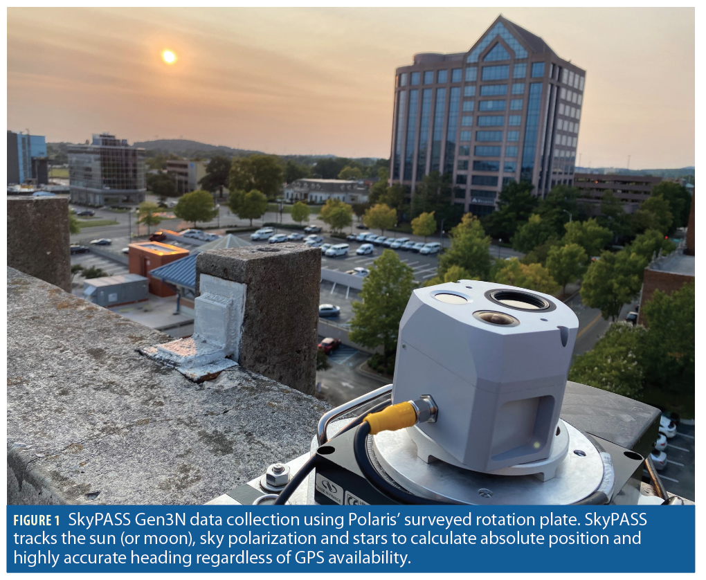
SkyPASS has a demonstrated RMS heading accuracy less than 2mils (0.1°) in good conditions (clear to partly cloudy skies). The sensor acts as a “guard band” to typical inertial measurement units (IMU), providing the performance of an expensive IMU system in a smaller, lower power package. SkyPASS Gen3N (Figure 1) uses dual sensing modalities (sun|polarization or moon|stars), when available, to provide redundancy and improved accuracy. The size, weight and power of the Gen3N system is 4.1 x 3.9 x 3.2 inches, 20 oz, and <5 W, respectively. An internal attitude and heading reference system (AHRS) provides pitch and roll for the system to correct for tilt. The SkyPASS sensors have embedded processing and collect data in real time at 1 Hz.
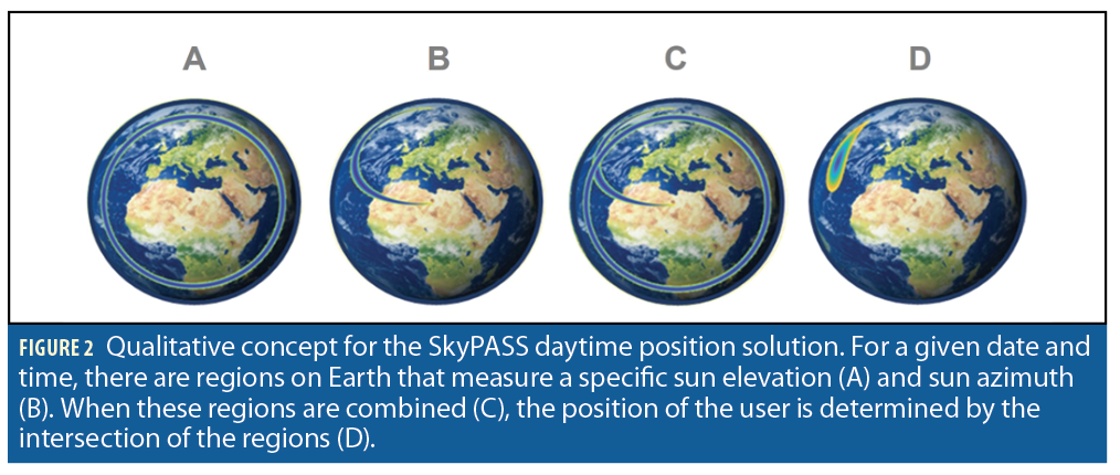
Polaris recently developed celestial positioning algorithms to determine absolute position estimates for both day and night operation using SkyPASS and inertial navigation system (INS) outputs. The nighttime celestial position algorithm uses an angles-only approach [2] and requires a unique set of four stars to be imaged and matched to a sky map (catalog). The daytime celestial position algorithm uses a direct closed-form equation that requires the measured position inputs (azimuth and elevation) of a celestial body, as well as heading from an external source. The qualitative concept for the daytime method can be observed in Figure 2.
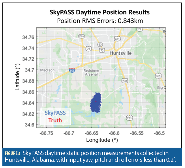
To evaluate the sensor in operationally relevant environments, testing of the daytime celestial position and nighttime star tracking solutions in static and dynamic operating modes, and in varying seasons, locations (including high latitudes), and times of day (including dusk and dawn) is on-going. Initial position accuracy on startup (no averaging) is less than 3 km for both day and night operating modes (Figure 3).
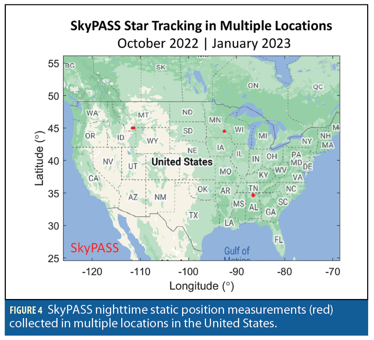
SkyPASS measurement error for position is less than 0.05° when optimized and in static operation; however, measurement errors less than 0.001° are needed to achieve position accuracy less than 100 m. Given time to collect a series of measurements or when using a better grade INS, SkyPASS can achieve position accuracy down to 100 m. Polaris is actively investigating hardware upgrades, implementing improved star catalogs with satellite/resident space object (RSO) tracking, averaging, and feedback looping with an INS Kalman filter to achieve position errors less than 100 m. Measurement locations where the SkyPASS star tracking solution was used are shown in Figure 4.

Unique Navigation Source: Sky Polarization
Inspired by nature, the SkyPASS polarimeter [1, 3-5] exploits the atmospheric polarization pattern to find highly accurate heading in situations when typical sun and star sensors fail to operate. It provides improved availability under cloud cover, under canopy, in urban environments, in civil and nautical twilight, and during sunrise and sunset. Unpolarized sunlight (or moonlight) becomes partially polarized when scattered by atmospheric molecules. Rayleigh scattering creates a polarization pattern, or map, that is unique, depending upon the date, time and position of the observer. This natural phenomenon is the scientific basis for SkyPASS operation, and can be predicted to first order using Rayleigh scattering theory. Polarized light provides valuable navigation information [6-8] and has been used by insects and birds in nature [9-11] and by the Vikings [12] for direction finding.
Imaging Polarimetry
Polarization is a fundamental property of light and its measurement enhances traditional sensing methods that measure the brightness and color of a scene. Light is an electromagnetic wave that consists of transverse electric and magnetic fields that oscillate in perpendicular planes with respect to each other. The electric field direction defines the polarization state of light. Light can be linearly, circularly and randomly polarized. Polarimetry is simply the measurement of the polarization content of a scene and can be accomplished by capturing images at multiple orientations of a linear or circular polarizer that act as a polarization filter. The amount of polarized light that passes through a polarizer depends on the angle between the axis of the polarized light and the axis of the polarized filter. This can be observed using polarized sunglasses and tilting your head (or rotating the glasses) while looking at the sky (Figure 5) because scattered sunlight is polarized.
The degree of linear polarization (DoLP) and the angle of polarization (AoP), derived from the Stokes parameters, are two important quantities used to characterize polarization and to calculate heading. In the Stokes vector,

Ex and Ey are the component electric field amplitudes, and I is the radiance collected by the sensor. The subscripts of I correspond to the orientation of the linear polarizer. Linear polarization at 0° and 90° are horizontally and vertically polarized, respectively. S0 represents the overall intensity (radiance), S1 represents the preference for horizontally polarized light (difference between 0° and 90° polarization), S2 represents the preference for light polarized at 45° over light polarized at 135°, and S3 represents the difference between right- and left-hand circular polarized light.
The DoLP represents the percentage of light that is linearly polarized and is defined as
where a result of 0 indicates unpolarized light and a result of 1 indicates 100% polarized light. Intermediate values represent partially polarized light. Typically, the Stokes vector is normalized meaning S1 and S2 range over [-1,1] and S0 = 1.
The AoP is an important quantity that represents the measured orientation of the polarization vector (from 0° to 180°). The AoP can be determined using the Stokes parameters and the following equation:

Rayleigh Scattering → Atmospheric Polarization
Within Earth’s atmosphere, Rayleigh scattering of light causes a defined polarization pattern, which is dependent on the celestial position of the sun (or moon at night) and the relative position and pointing angle of the observer [13,14]. Rayleigh theory, a subset of Mie theory [15], requires that the scattering molecules be small compared to the incident wavelength and that the scattered light experiences a single scattering effect prior to measurement. The scattered light becomes linearly polarized at varying degrees with a particular polarization orientation that depends on the geometry of the source-scatterer-sensor configuration [16-19].
The DoLP of sky polarization can be derived based on the geometry of the source-scatterer-sensor arrangement and is useful for predicting the sky polarization properties. The DoLP relates to the scattering angle (θ), which is the angle between the light’s initial direction connecting the sun and target positions and the scattered light’s new direction (i.e., from the target position to the sensor). By using Equation 4, the DoLP for any position in the sky can be predicted by knowing the sun, target and sensor positions while Equation 2 can be used to calculate sky polarization via polarimetric measurements. As expected, viewing the sun directly, which implies no scattering (θ=0°), results in DoLP=0 (S1=S2=0). Similarly, viewing a target position where θ=90°, results in DoLP=1 (S1=1, S2=0,).

DoLPmax is a constant that represents the maximum DoLP in the sky at a particular moment and is dependent on atmospheric humidity, aerosols content, optical density, and time of day.
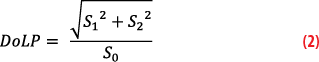
On clear days at either sunrise or sunset, a maximum band of polarization extends from the horizon through the zenith, approximately 90° from the sun (Figure 7). In general, the sky DoLP increases from the sun to the maximum band of polarization, then decreases toward the anti-sun position. The maximum band of polarization shifts based on the position of the sun. Therefore, at midday when the sun is high in the sky, sky polarization observed at the zenith is minimal. Multiple scattering from aerosols [20-21], clouds [22-24] and the underlying surface [25,26] can reduce the degree of polarization; however, the direction of polarization remains similar for clear and slightly overcast skies [27,28]. The AoP direction is normal to the scattering plane that contains the sun, target and sensor and for any given time, sensor position, and target position in the sky, the AoP can be predicted based solely on the geometry of the situation.
Measured all-sky AoP and DoLP images of the sky at sunrise, with the sun directly on the horizon and above the observer are shown in Figure 8. Zenith is at the center and the circumference of the image represents positions along the horizon. In general, the DoLP increases as one moves away from the sun until it reaches a maximum at θ=90° and then it decreases back to zero at the anti-sun position.
In the AoP image, a symmetric pattern is observed, with a line connecting both the sun and the zenith. For navigation purposes, this map is more informative than the DoLP image because a complete hemispherical image is not required to determine the position of the sun, which relates to the pointing direction of the platform. The relative position of the sun can be measured without directly seeing the sun. If the sun is blocked by clouds, buildings or foliage or if it is below the horizon during twilight, sky polarization can be observed to determine the position of the sun that is required to find heading and absolute position for the end user.

The SkyPASS Polarimeter
The SkyPASS polarimeter is a visible imaging polarimeter that measures the first three Stokes parameters (S0, S1, S2) at the zenith. It employs an architecture with three lens arrays (channels) projecting a target scene to separate locations on the focal plane array (FPA). Each channel contains a uniquely oriented linear polarizer resulting in three individual polarized images.
Algorithms to detect and decipher the polarization map of the sky can be used to compute highly accurate heading based on known date, time and user position. The reported confidence metric is determined by sky and lighting conditions. Full image algorithms are in development that expand the capability of the polarization channel. These algorithms improve heading performance, position capability and availability in cloudy conditions. If blue sky is visible, SkyPASS can produce a heading/position result.
Implementing the full image algorithms using the SkyPASS polarimeter is on the technology roadmap for SkyPASS. Proof-of-concept has been demonstrated through post-processing images in MATLAB. SkyPASS Gen3N has an embedded processor and collects data in real-time at 1 Hz. The daytime integration time for the polarimeter ranges from 5ms to 30ms depending on design considerations for field of view and twilight optimization. The maximum integration time is 1600ms. The operation of the polarimeter is limited to tilt angles less than 13° due to the sensor’s field of view (FOV). The performance of the SkyPASS system is characterized using a surveyed rotation plate and a 3-axis gimbal to evaluate the performance of the sensing modalities at different tilt angles.
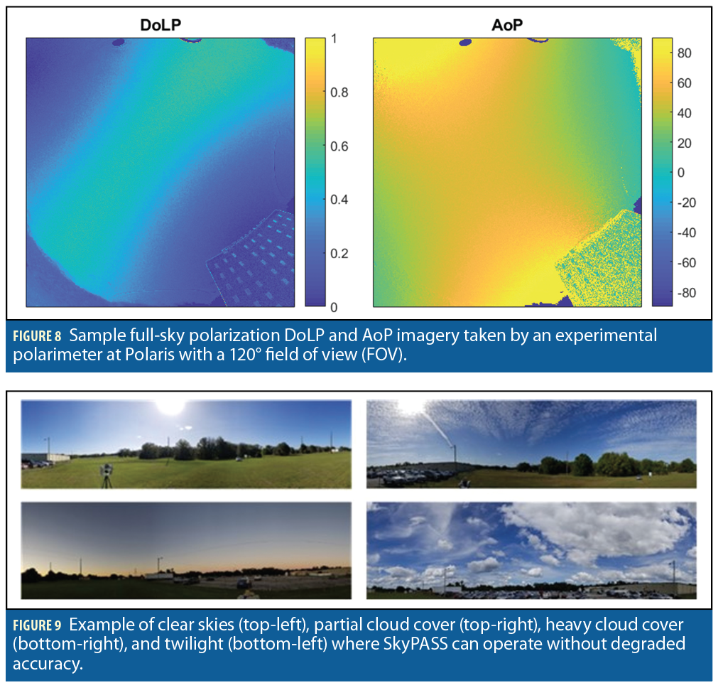
The objective for the SkyPASS sensor is to provide 24-hour, all weather operation. System capabilities and limitations in GPS-denied environments, in clear and cloudy skies, and in twilight are presented in the subsequent subsections. For reference, example sky conditions are shown in Figure 9.
GPS-Denied Operation
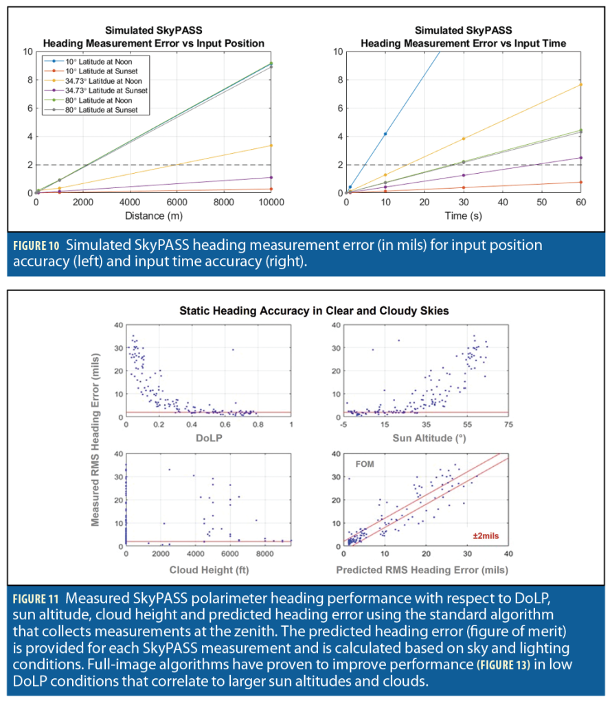
To find North (heading) from sky polarization measurements, the date, time and the position of the user must be known. The accuracy of the SkyPASS polarimeter directly relates to the input position error and the input time error. Simulated results in Figure 10 were generated using a solar position calculator, accurate to within 0.0003°, for various latitudes and times of day.
For the simulation, distances representing position errors were measured in longitude, as they had a larger impact on heading measurement error. Results were dependent on the distance to the solar ecliptic. These scenarios were completed for spring equinox, so that the ecliptic was on the equator. The results in Figure 10 represent GPS-denied scenarios where sensors are unable to update the sensor position to accommodate the loss of GPS (left), and GPS-denied scenarios where the sensors lose a precise time estimate from GPS signals (right).
The results show that higher latitudes near the poles will yield larger overall errors and that 10 seconds of error for specific cases will impact the performance of the SkyPASS polarimeter. Thus, when losing GPS signal, the SkyPASS polarimeter would need a clock to sustain the GPS time to within 1s for the life of the expected operation. Adding a clock to the SkyPASS system architecture is on the technology roadmap for SkyPASS. Overall, a position input with accuracy of less than 1km and a time input with accuracy of less than 1 second should have no measurable impact on the accuracy of the SkyPASS sensor heading results (0.1125° or 2mils).
Performance at the Zenith
The SkyPASS polarimeter has the best performance when the polarization signal is highest during sunrise and sunset, which is when traditional sun, moon and star tracking solutions fail. Either the sky is too bright for star tracking or the sun (or moon) has not yet cleared the horizon or terrain. The best sky polarization signal is 90° away from the sun, so a sensor looking at zenith is going to perform best when the sun is near the horizon. This functionality complements the sun channel because the sun is visible at higher elevations and is more likely to be occluded near the horizon when the polarization signal is high.
The polarimeter can collect accurate data until about 30 minutes before sunrise and after sunset (civil-to-nautical twilight). At this point, the light level and the signal-to-noise ratio become too low to achieve reasonable sky polarization measurements. More flexibility in integration time/gain adjustment and changes to the optical design have proven accurate measurements can be extended beyond civil twilight; however, physical limitations due to scattered skylight and moonlight interactions exist where the observed AoP pattern becomes random and not predictable in astronomical twilight and at night [12,29].
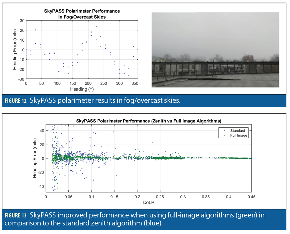
The ideal operation to achieve heading accuracy less than 2mils with the SkyPASS polarimeter is between sun altitudes of -4° and 35° in clear, non-overcast skies and in static operation. The performance of the SkyPASS polarimeter degrades in cloudy conditions and for higher sun altitudes when only measuring sky polarization at the zenith. This can be observed in Figure 11 where degraded performance corresponds to lower DoLP values. In addition to low DoLP, degraded performance can correspond to saturation of signals from clouds or lack of signal during sunrise/sunset. In the current configuration, the SkyPASS polarimeter can achieve higher accuracy and better availability with a reduced FOV of the sky; however, by reducing the FOV, the tilt capability of the sensor is limited. There is a tradeoff between performance versus operational platform orientation.
In general, if clouds are blocking the zenith, the polarization channel will not report a heading. Polaris has not conducted an in-depth examination of this, but the polarization channel can be operational, albeit severely degraded, in fog (Figure 12). More work is required to characterize and improve the performance of the polarization in fog and overcast skies.
Performance with Full Image Algorithms
A polarimeter that uses full-image algorithms has the capability to select regions of interest (ROIs) with high DoLP values, leading to more accurate heading (Figure 13) and absolute position solutions. By implementing the full-image algorithms, the sun azimuth and sun elevation can be found from a polarization channel image with any sensor orientation. These parameters are required to determine position using the daytime celestial position algorithm developed by Polaris.
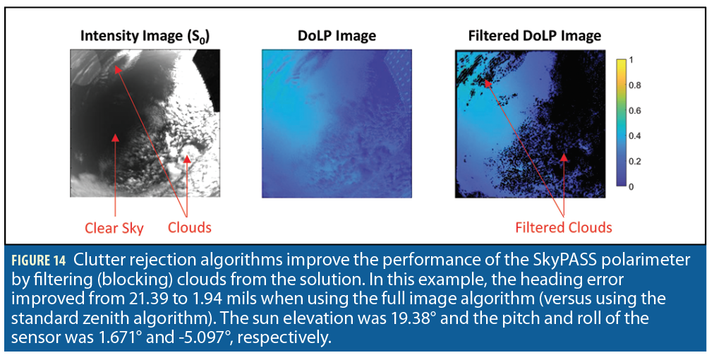
A clutter rejection algorithm to only use clear blue portions of the sky to determine heading (azimuth) and elevation has also been developed by Polaris. This edge detection algorithm uses 2D convolutions to reject the majority of clouds, buildings, building edges, and windows while preserving the clear sky. The windows are true sources of polarization but are small enough compared to the large, slowly varying sky that a tuned algorithm will treat them as edges and reject them as observed in Figure 14. At this time, a correlation with relative sun elevation exists using the full image algorithm; however, this method works when zenith is not in the image (sensor tilted past 15°).
Expanding the tilt capability for the SkyPASS polarimeter beyond 13° is achievable using full image algorithms. Polaris has also determined that current processing resources support implementation of the full image algorithms. Implementing the full image algorithms using the SkyPASS polarimeter is on the technology roadmap for SkyPASS and proof-of-concept has been demonstrated through post-processing of images in MATLAB.
Final Remarks
SkyPASS is a modern-day digital celestial compass/sextant that provides highly accurate heading and absolute position in a GPS-denied environment by tracking the sun, stars and sky polarization. SkyPASS is fast and easy to use because it has an immediate time-to-fix and does not require any setup or leveling. It can be used on almost any platform including drones, vehicles, personnel, far-target locators, watercraft and aircraft. The SkyPASS solution does not drift, is spoof-proof, is not affected by magnetic disturbances and operates during the day, in twilight and at night.
Inspired by nature, the SkyPASS polarimeter exploits the atmospheric polarization pattern to find highly accurate heading and absolute position. Sky polarization patterns provide strong gradient information describing the sensor’s absolute heading. Operation at sunrise, sunset and during cloudy days is possible at accuracies that outperform current celestial, inertial and vision-based methods. Degraded performance is observed in heavy cloud cover and in dynamic conditions. Nighttime polarization has been demonstrated as an orientation method in the animal kingdom; however, while theoretically possible and achievable in a contrived setup (nonmoving platform, long integration times, non-urban environment, etc.), nighttime sky polarization sensing is unlikely to significantly outperform other nighttime sensing methods such as star and moon tracking.
Acknowledgements
This work is supported by the Naval Air Systems Command Multi-Mission Tactical UAS Program Office (PMA-266) and the Naval Air Systems Command Small Business Innovation and Research (SBIR) Office.
References
- Aycock, T., Chenault, D., Lompado, A., and Pezzaniti, J. L., “Sky polarization and sun sensor system
and method,” U.S. Patent 9 423 484, (2016). - Kaplan, G. H.: “Angles-Only Navigation: Position and Velocity Solution from Absolute
Triangulation”, Navigation, Vol. 58, No. 3 (2011),
https://gkaplan.us/content/nav_by_angles_ION_v5.pdf. - Aycock, T., Lompado, A., and Wheeler, B., “Using atmospheric polarization patterns for azimuth
sensing,” Proc. SPIE 9085, Sensors and Systems for Space Application VII, 90850B (2014)
HTTPS://DOI.ORG/10.1117/12.2054107. - Smith, A. M., Pezzaniti, J. L., Chenault, D. B., and Lompado, A., “Study of natural down-welling sky
light with imaging spectro-polarimeter,” Proc. SPIE 10655, Polarization: Measurement, Analysis, and
Remote Sensing XIII, 106550M (2018). https://doi.org/10.1117/12.2310007. - Eshelman, L. M., Smith, A. M. Smith, K. M., and Chenault, D. B., “Unique navigation solution
utilizing sky polarization signatures,” Proc. SPIE 12112, Polarization: Measurement, Analysis, and
Remote Sensing XV, 1211203 (2022) https://doi.org/10.1117/12.2623503. - Guan, G., Gu, J., and Wu, M., “The novel method of north finding based on the skylight
polarization,” J. Eng. Sci. Tech. Rev., 6(1), 107-110 (2013). - Sarkar, M., San Segundo Bello, D., van Hoof, C., and Theuwissen, A., “Biologically inspired
autonomous agent navigation using an integrated polarization analyzing CMOS image sensor,”
Proc. Eng., 5, 673-676 (2010). - Karman, S.B., Diah, S.Z.M, and Gebeshuber, I.C., “Bio-inspired polarized skylight navigation
sensors: A review,” Sensors, 12, 14232-14261 (2012). - Mathejczyk, T. and Wernet, M., “Sensing polarized light in insects’” Oxford Research Encyclopedia
of Neuroscience, (2017) HTTPS://DOI.ORG/10.1093/ACREFORE/9780190264086.013.109. - Dacke, M., Nordström, P., and Scholtz, C. H., “Twilight orientation to polarised light in the
crepuscular dung beetle Scarabaeus zambesianus,” J Exp Biol, 206 (9): 1535–1543
(2003). https://doi.org/10.1242/jeb.00289. - Sakura, M., Lambrinos, D., and Labhart, T., “Polarized skylight navigation in insects: model and
electrophysiology of e-vector coding by neurons in the central complex,” J Neurophysiol, 99(2):6, 67-
82 (2008). - Barta, A., Farkas, A., Száz, D., Egri, Á., Barta, P., Kovács, J., Csák, B., Jankovics, I., Szabó, G., and
Horváth, G., “Polarization transition between sunlit and moonlit skies with possible implications for
animal orientation and Viking navigation: anomalous celestial twilight polarization at partial moon,”
Appl Opt., 53(23):5, 193-204 (2014). - Strutt, J., “On the light from the sky, its polarization and colour,” Philosophical Magazine, Vol. 41
(4), 107-120 (1871). - Strutt, J, “On the transmission of light through an atmosphere containing small particles in
suspension, and on the origin of the blue of the sky,” Philosophical Magazine, Vol. 47 (5), 375-393,
(1899). - Fu, Q., and Sun, W., “Mie theory for light scattering by a spherical particle in an absorbing medium,”
Applied Optics, V. 40(9), 1354-1361, (2001). - Van de Hulst, H.C., [Light Scattering by Small Particles], Dover Publications, New York, Chap. 6
and 7, (1981). - Können, G. P., [Polarized Light in Nature], Cambridge University, (1985).
- Bohren, C. F., and Huffman, D. R., [Absorption and Scattering of Light by Small Particles], John
Wiley and Sons, Inc., New York, 130-136 (1998). - Coulson, K. L., [Polarization and Intensity of Light in the Atmosphere], Deepak Publishing, (1988).
- Boesche, E., Stamnes, P., Ruhtz, T., Preusker, R., and Fischer, J., “Effect of aerosol microphysical
properties on polarization of skylight: sensitivity study and measurements,” Appl. Opt.45, 8790–8805
(2006). - Kreuter, A., Emde, C., and Blumthaler, M., “Measuring the influence of aerosols and albedo on sky
polarization,” Atmos. Res. 98, 363–367 (2010). - Pust, N. J., and Shaw, J. A., “Digital all-sky polarization imaging of partly cloudy skies,” Appl. Opt.
47, H190–H198 (2008). - Eshelman, L. M., Tauc, M. J., and Shaw, J. A., “All-sky polarization imaging of cloud
thermodynamic phase,” Opt. Express 27, 3528–3541 (2019). - Horváth, G., Barta, A., Gál, J., Suhai, B., and Haiman, O., “Ground based full-sky imaging
polarimetry of rapidly changing skies and its use for polarimetric cloud detection,” Appl. Opt.41,
543–559 (2002). - Dahlberg, A. R., Pust, N. J., and Shaw, J. A., “Effects of surface reflectance on skylight polarization
measurements at the Mauna Loa Observatory,” Opt. Express19, 16008–16021 (2011). - Eshelman, L. M., and Shaw, J. A., “The VIS-SWIR spectrum of skylight polarization,” Appl. Opt.57,
7974–7986 (2018). - Hegedus, R., Akesson, S., and Horváth, G., “Polarization patterns of thick clouds: overcast skies have
distribution of the angle of polarization similar to that of clear skies,” J. Opt. Soc. Am. A, 24(8),
2347- 2356 (2007). - Pomozi, I., Horváth, G., and Wehner, R., “How the clear-sky angle of polarization pattern continues
underneath clouds: full-sky measurements and implications for animal orientation,” J. Exp. Biol. 204,
2933–2942 (2001). - Gal, J., Horváth, G., and Barta, A., “Polarization of the moonlit clear night sky measured by full-sky
imaging polarimetry at full Moon: Comparison of the polarization of moonlit and sunlit skies,”
Journal of Geophysical Research, Vol. 106, No. D19, pp. 22,647-22,653, 2001.
Author
Dr. Laura Eshleman is the SkyPASS Product Lead for Polaris Sensor Technologies and is currently working to expand and promote the capabilities of SkyPASS for GPS-denied navigation, localization and targeting applications. Her work has centered around developing optical remote sensing systems for environmental science and navigation. Dr. Eshelman received her undergraduate degree in Physics from Gustavus Adolphus College and her MS degree and Ph.D. in Electrical Engineering from Montana State University.


