
A framework to seamlessly navigate people from urban road traffic to indoor foot traffic uses the phone’s inertial measurement unit, GNSS chipset and camera, aided by an extended Kalman filter and ORB-SLAM. Tests show the framework performing well in both phases, guiding the phone’s user, behind the wheel on a city street, to a spot in an underground parking garage and walking to a meeting inside a large building.
By Kai-Wei Chiang, Dinh Thuan Le, Kuan-Ying Lin and Syun Tsai, National Cheng Kung University, Taiwan
Modern mobile phones are powerful processing devices with a host of onboard technologies of interest to navigation system designers: camera, GNSS, gyroscope, accelerometer, magnetometer, and more. Here we propose a framework to seamlessly navigate people from a road vehicle in an urban area to pedestrian travel in an indoor environment, using these smartphone sensors.
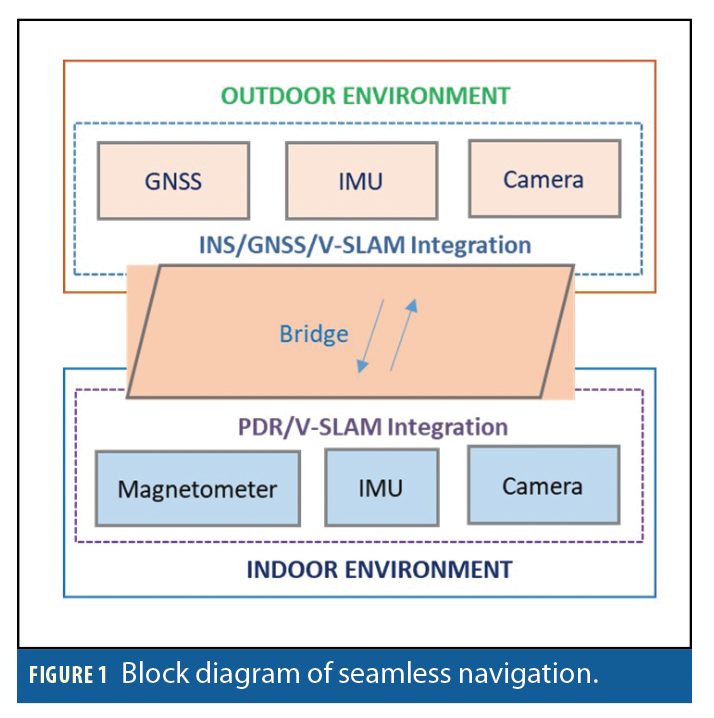
The framework for seamless navigation includes two phases, corresponding to the outdoor and indoor environments. The outdoor phase integrates GNSS, the inertial measurement unit (IMU) and camera, whereas the indoor phase uses data from the phone’s magnetometer, IMU and camera. We chose ORB-SLAM, an open-source simultaneous localization and mapping solution for monocular cameras, able to compute in real-time the camera trajectory and a sparse 3D reconstruction of the scene, as a visual SLAM (V-SLAM) method to process data from the camera in both phases. Figure 1 describes this framework.
Outdoor Phase
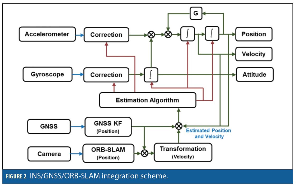
The proposed integration scheme for the outdoor phase is presented in Figure 2. Considering the stability of the structure and the computational cost for multi-sensor fusion, the system uses a loosely coupled scheme of inertial/GNSS/ORB-SLAM integration.
The core system dynamic model for estimation is chosen to be the inertial navigation equations in local level frame:

where:  is the time derivative of position in local level frame.
  is time derivative of velocity.
  is time derivative of attitude.
  is specific force, sensed by accelerometer.
  is angular velocity of the body frame relative to the inertial frame, parameterized in body frame.
  is transformation matrix from body frame to local level frame.
  are the rotation rate of the Earth with respect to the inertial frame and rotation rate of local level frame with respect to the Earth. The matrix D−1 converts the linear velocity values to angular changes in latitude and longitude.
In practice, to avoid singularity, a quaternion is used to express the attitude.
During operation, the measured acceleration and rotation rate suffer from biases, scale factors and noises. To determine and compensate those errors for IMU measurements, the bias, scale factor and noise of accelerometer and gyroscope will be included in the system dynamic model for estimation.
The state model can be written as:

Its discrete-time equation is:

where  is the state vector, including the components of position, velocity, attitude error, biases, and scale factors of gyroscope and accelerometer, respectively. F is the state continuous time transition matrix,
  is the state transition matrix from epoch k to k+1, and wk is the system noise.
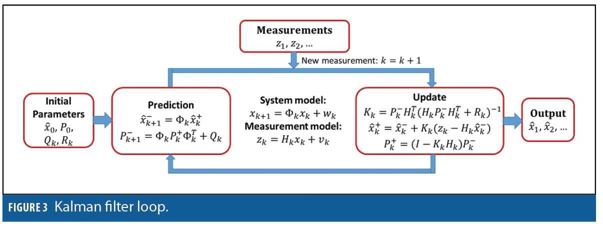
Kalman Filter. EKF equations are divided into two groups; time prediction and measurement update. The time prediction equations are responsible for the forward time transition of the current epoch (k) state to the next epoch (k+1) state. The components and sequence of computational steps are shown in Figure 3.
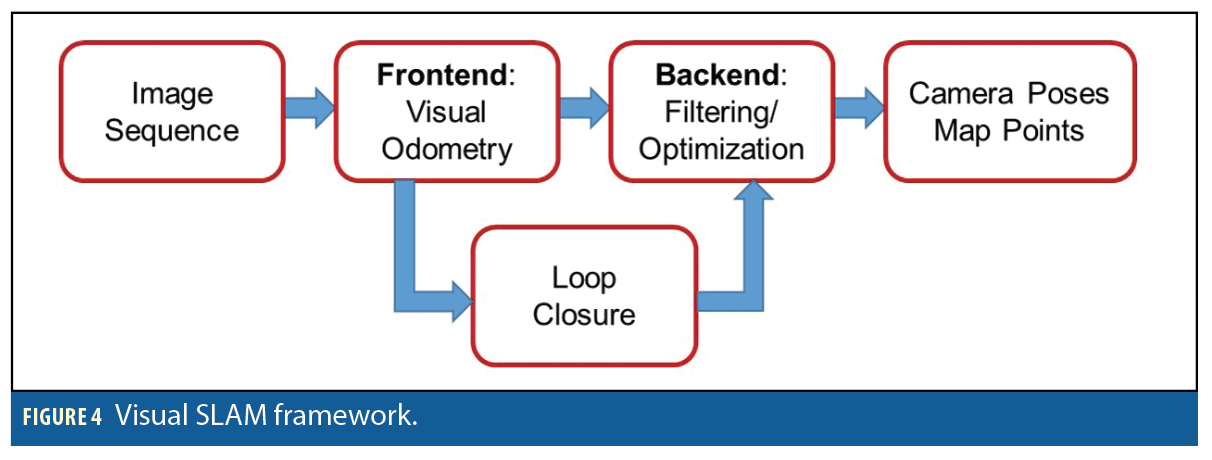
Visual SLAM. V-SLAM is the process of using camera to build a map of an unknown environment and at the same time estimate the camera pose in this environment. Figure 4 shows the chart of V-SLAM. Two different V-SLAM methodologies predominate: filtering methods and keyframe methods.
In filtering methods, the camera poses and all the map features are utilized to process at every frame, whereas in keyframe methods, the camera pose is estimated using a subset of the entire map, without the need to update the map’s features at every processed frame. Therefore, processing time is reduced significantly in keyframe methods, making them possible for real time. Moreover, filtering methods use a linearization process, so they suffer from accumulation errors. Overall, keyframe methods have some advantages compared to filtering methods in terms of processing time as well as accuracy.
ORB-SLAM, a keyframe-based visual SLAM system, builds on recently developed algorithms and uses the same features for all SLAM tasks: tracking, mapping, relocalization, and loop closing, giving vision-based navigation good robustness. We selected ORB-SLAM to process image sequences from the camera to provide translation up to scale in the initial camera frame. This translation is re-scaled by the assistance of GNSS measurements and transformed to velocity in the navigation frame before updating the system.
Indoor Phase
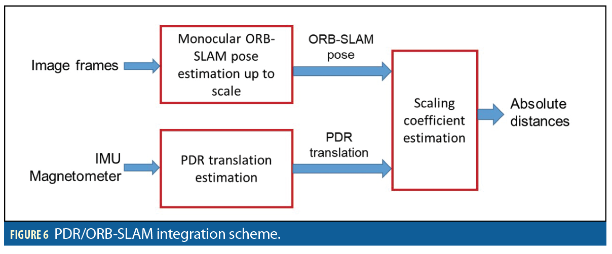
Pedestrian dead reckoning (PDR) uses a pedometer, step-length model and heading sensors to obtain positions rather than continuously producing integral calculations like inertial navigation systems (INS). Figure 5 shows the basic PDR concept and general block diagram.
For the indoor phase we integrated PDR and ORB-SLAM. Following this fusion, ORB-SLAM bounds the accumulated error from PDR and PDR will help ORB-SLAM in terms of recovering metric distance. The integrated architecture is illustrated in Figure 6.


Field Tests
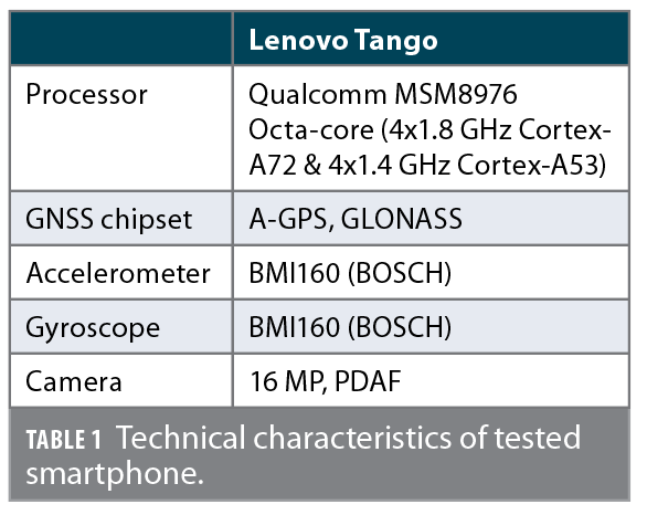
The smartphone used for testing in this study was Lenovo Tango with Android operating system. Table 1 summarizes its technical characteristics. The outdoor test was conducted using a sport utility vehicle (SUV) as platform, with the smartphone seated in a cradle attached to the front windshield (Figure 7). The smartphone was roughly aligned with the vehicle frame. The SUV was driven along streets of Tainan, Taiwan and through the underground parking lot of the Main Library of National Cheng Kung University for a total distance of 1.7 kilometers.
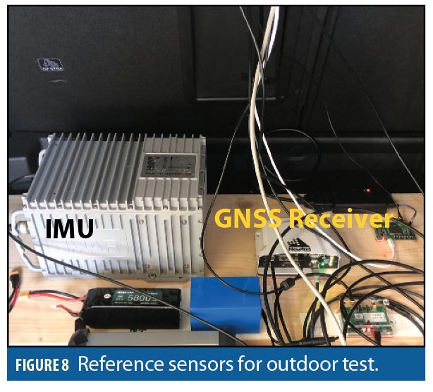
The navigation system used to provide the reference trajectory as ground truth for the outdoor test integrates a precision GNSS and IMU: PwrPak7D-E1 from NovAtel, and a navigation-grade iNAV-RQH (iMAR), both shown in Figure 8. In this work, the tightly coupled strategy together with smoother were applied using the commercial INS/GNSS processing software Inertial Explore (IE) 8.70. There was a lever-arm between the reference system and smartphone, so the “true” position and velocity were converted to the center of the smartphone when exported the reference solutions from IE software.
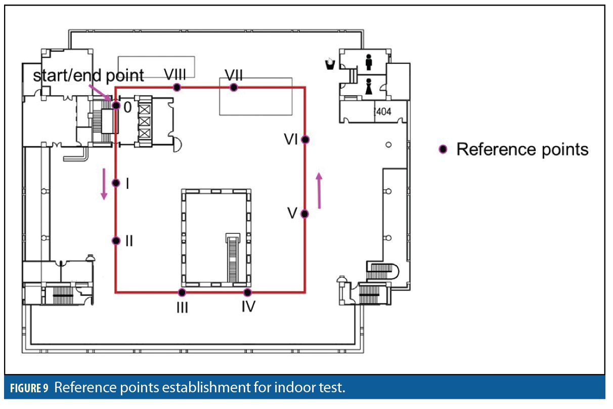
The indoor test was conducted by a person taking the smartphone and walking on a rectangular trajectory inside the Main Library. To evaluate performance of the indoor phase, nine reference points were established on the floor using a laser distance measure (Figure 9).
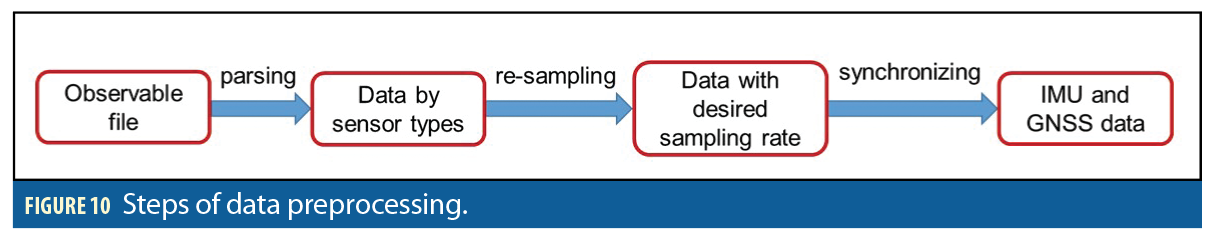
Data Recording and Preprocessing. Many free smartphone apps collect sensor data. However, it is difficult to find one that can record data from the magnetometer, IMU, GNSS chipset, and camera at the same time. To overcome this problem, our lab’s members developed an Android app that does so. The raw data includes a video file and mixed file with the GNSS position, magnetometer, and IMU (accelerometer and gyroscope) observations. This observable file is parsed by sensor type. Then, they are re-sampled to the desired sampling rate. Finally, accelerometer and gyroscope data are synchronized together as IMU data. Figure 10 describes this process.
Results of Outdoor Navigation
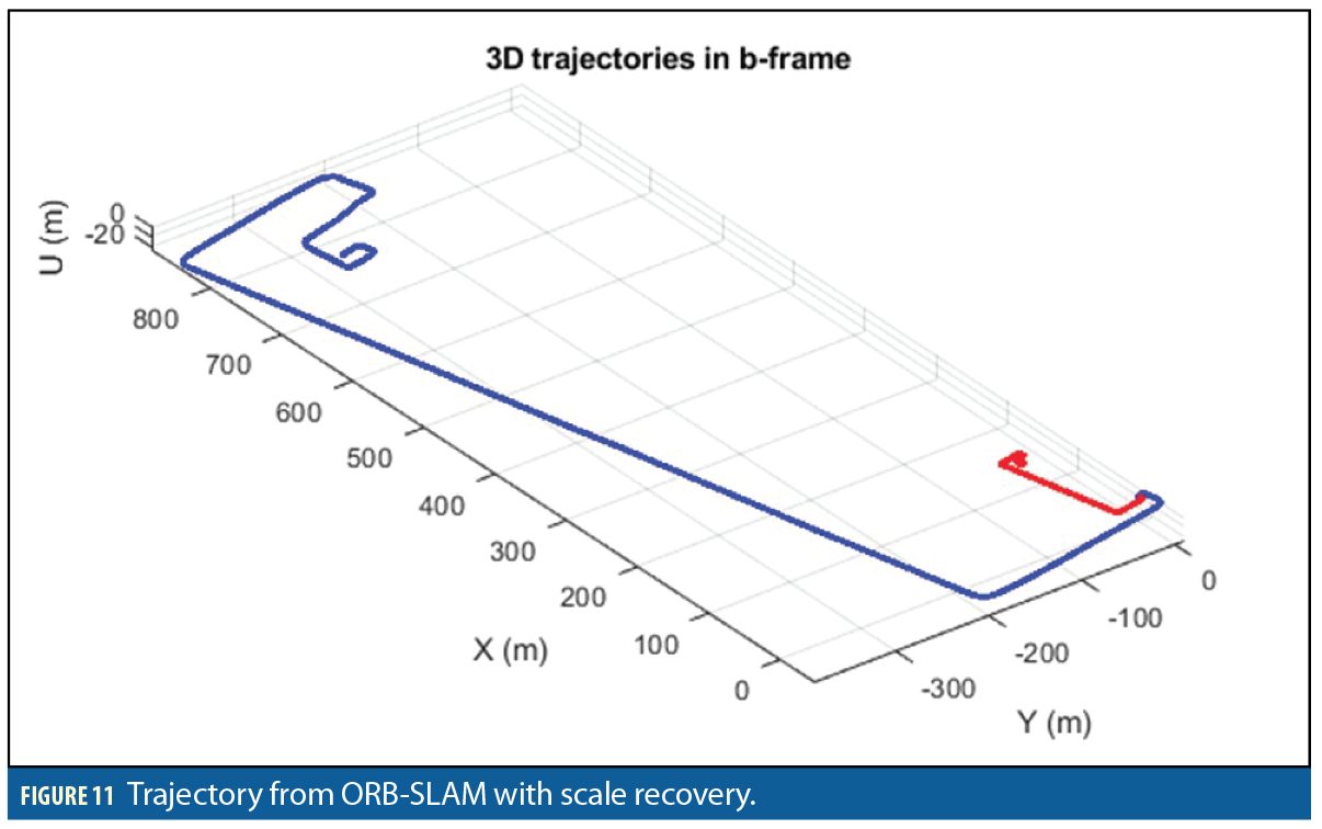
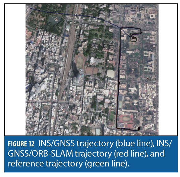
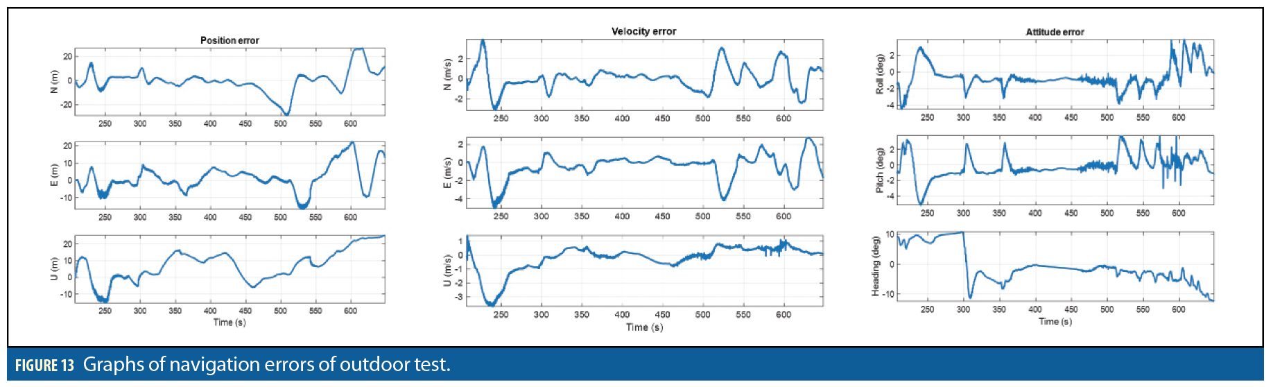
For performance evaluation, the solution provided by INS/GNSS/ORB-SLAM was analyzed. Figure 11 shows trajectories before and after scale recovery. The red line trajectory from pure ORB-SLAM is up to scale, and blue line is trajectory with absolute scale. Figure 12 shows trajectories of INS/GNSS integration in blue, INS/GNSS/ORB-SLAM integration in red, together with reference in green. Figure 13 shows the navigation errors graphs obtained by comparing test solutions and truth reference. The first and second columns show the position and velocity errors of North, East, and up directions, respectively; the third column shows the attitude errors along roll, pitch, and yaw axes.
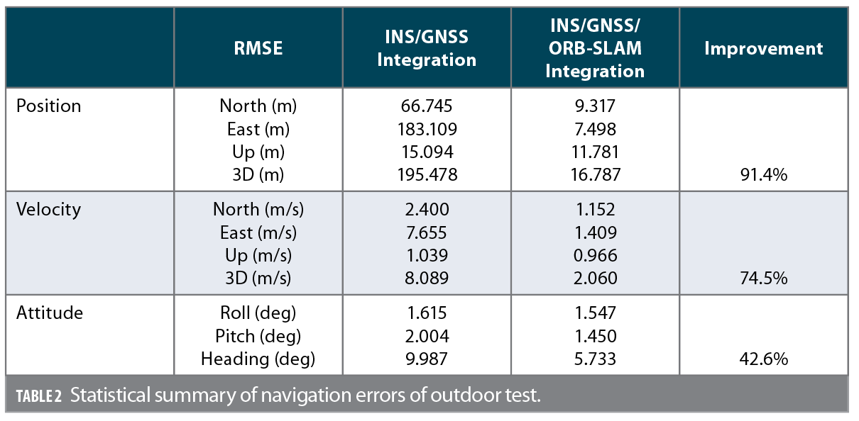
The numerical statistical summary in terms of root-mean-square error (RMSE) of the position, velocity, and attitude corresponding to INS/GNSS and INS/GNSS/ORB-SLAM integration is shown in Table 2. Considering the different error behaviors along North, East, and up directions for position, velocity, and attitude, they are given separately in the table. Note that, in terms of position error, the 3D RMSE of INS/GNSS/ORB-SLAM integration solution reaches about 16 meters; an improvement of 91.4% compared to that of INS/GNSS scheme. This improvement in part of velocity is 74.5%. Heading achieves lowest improvement with 42.6%.
Result of Indoor Navigation
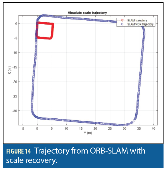
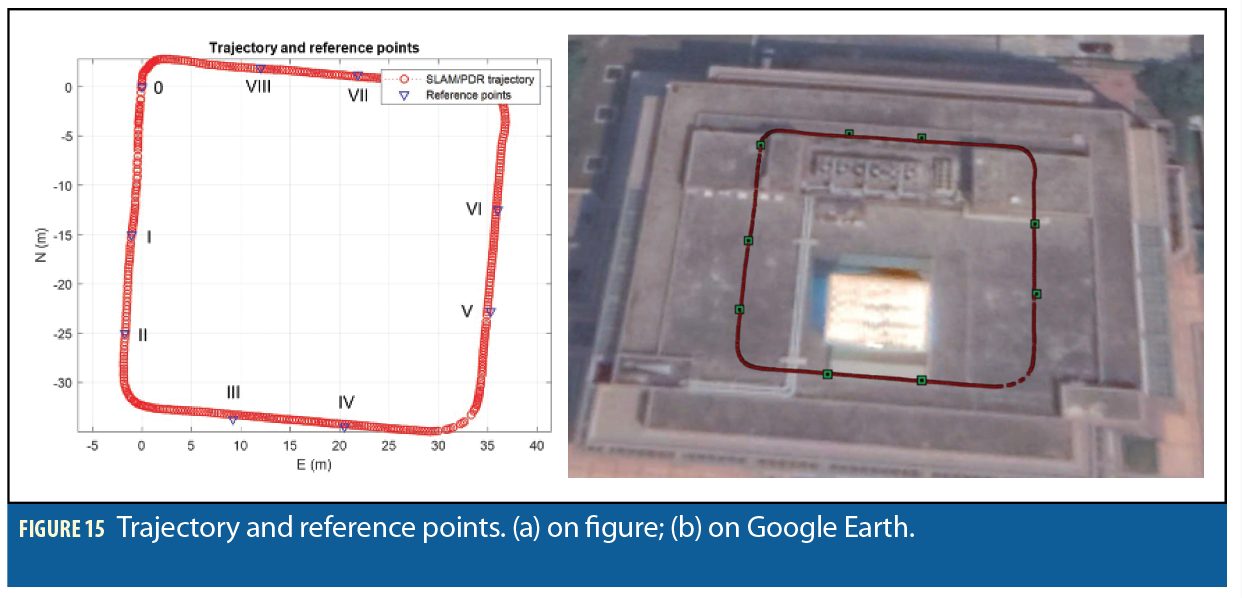
The trajectories from pure ORB-SLAM and ORB-SLAM/PDR solutions are displayed in Figure 14. The trajectories and reference points on figure and Google Earth are shown in Figure 15.
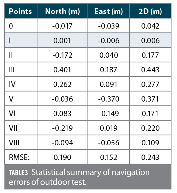
The position errors in North, East, and 2D corresponding to nine reference points are listed in Table 3. In general, the 2D position error of each point is smaller than 0.5 meters. The 2D RMSE is 0.243 meters.
Conclusions
Test results indicate that with the EKF used for data fusion, the RMSE of the 3D position in the outdoor test is about 90 times lower compared to that of the INS/GNSS-only scheme solution. Whereas, the improvement in heading is about 40%. The indoor test shows that maximum error in 2D is about 0.5 meters, and 2D RMSE is about 0.3 meters.
For future work, non-linear, non-Gaussian filtering will be applied in the integrated system to overcome the limitation of EKF in terms of error modelling and highly dynamic movement. This framework should be integrated in the smartphone environment and run directly in this platform.
Acknowledgments
The authors acknowledge the financial support through a project supported by the Ministry of Science and Technology (MOST 107-2221-E-006-125-MY3). This article is based on a paper presented at ION GNSS+ 2020 Virtual.
Authors
 Kai-Wei Chiang is a professor in the Department of Geomatics at National Cheng Kung University in Taiwan. He has a Ph.D. from the Department of Geomatics Engineering at the University of Calgary and also holds a M.Sc. in Geomatics Engineering from National Cheng Kung University. He has 15-years’ experience in geomatics engineering, formerly known as surveying engineering.
 Dinh Thuan Le is a Ph.D. candidate at the Department of Geomatics, National Cheng Kung University, Taiwan, with a Masters degrees from Hanoi University of Mining and Geology, Vietnam.
 Kuan-Ying Lin is a Ph.D. candidate at the Department of Geomatics, National Cheng Kung University, Taiwan.
 Syun Tsai is a Ph.D. student at the Department of Geomatics, National Cheng Kung University.


