
This article reviews some of the recent results analyzing the feasibility of carrier-phase based positioning with smartphone data and highlights limitations largely arising due to the poor antenna quality. It shows how they might be overcome by antenna calibration or coupling to the phone’s inertial sensors. The goal is to perform a successful RTK positioning with the smartphone-quality data.
The vast majority of GNSS receivers today are installed in smartphones, with 1.5 billion devices produced every year. Most of these new phones make GNSS raw measurements available to the applications, a feature supported by the Android operating system since 2017. This has led to many new smartphone applications and 1000+ research papers focusing on GNSS positioning with smartphones.
An increasing number of these phones support dual-frequency measurements on the L1 and L5 bands. The use of an additional frequency (L5/E5a) with higher chipping rate (10 times that of L1) produces a narrower correlation peak, making the measurements more precise and eliminating some of the multipath distortions. While these developments pave the way to transfer high-precision positioning technology from expensive professional devices to mass-market smartphones, there remains the major hurdle of successful carrier-phase positioning (i.e. ambiguity fixing) to overcome before reliable decimeter- or centimeter-level positioning can be achieved with phones.
Towards Centimeter-Level Positioning
To assess the suitability of the smartphone observations for cm-level positioning, the quality of the measurements must be investigated. Processing tools like RTKLIB, Inertial Explorer or GNSMART can be used for this task. To provide these tools sensor data from the smartphones, a logger is needed. This requirement leads to the development of Android-based logger applications that log GNSS measurements and inertial sensor data that can be processed with wide variety of processing tools available in the market.
The goal of this research is to perform a successful RTK positioning with the smartphone-quality data. The data logging and analysis was performed using the range of smartphones. Their names mentioned in the Manufacturers section are used throughout the article.
GNSS Data Logging
Until API Level 23 (Android 6 Marshmallow) it was only possible for the application developers to access the already estimated GNSS position and processed almanac. But with the new classes GnssMeasurements (the actual measurements of the signals of the built-in GNSS chips), GnssNavigationMessage (the bit-wise breakdown of the navigation message) and GnssClock (the clock parameters of the receiver) that were introduced in API Level 24, more advanced data is now available via the Android Location API.
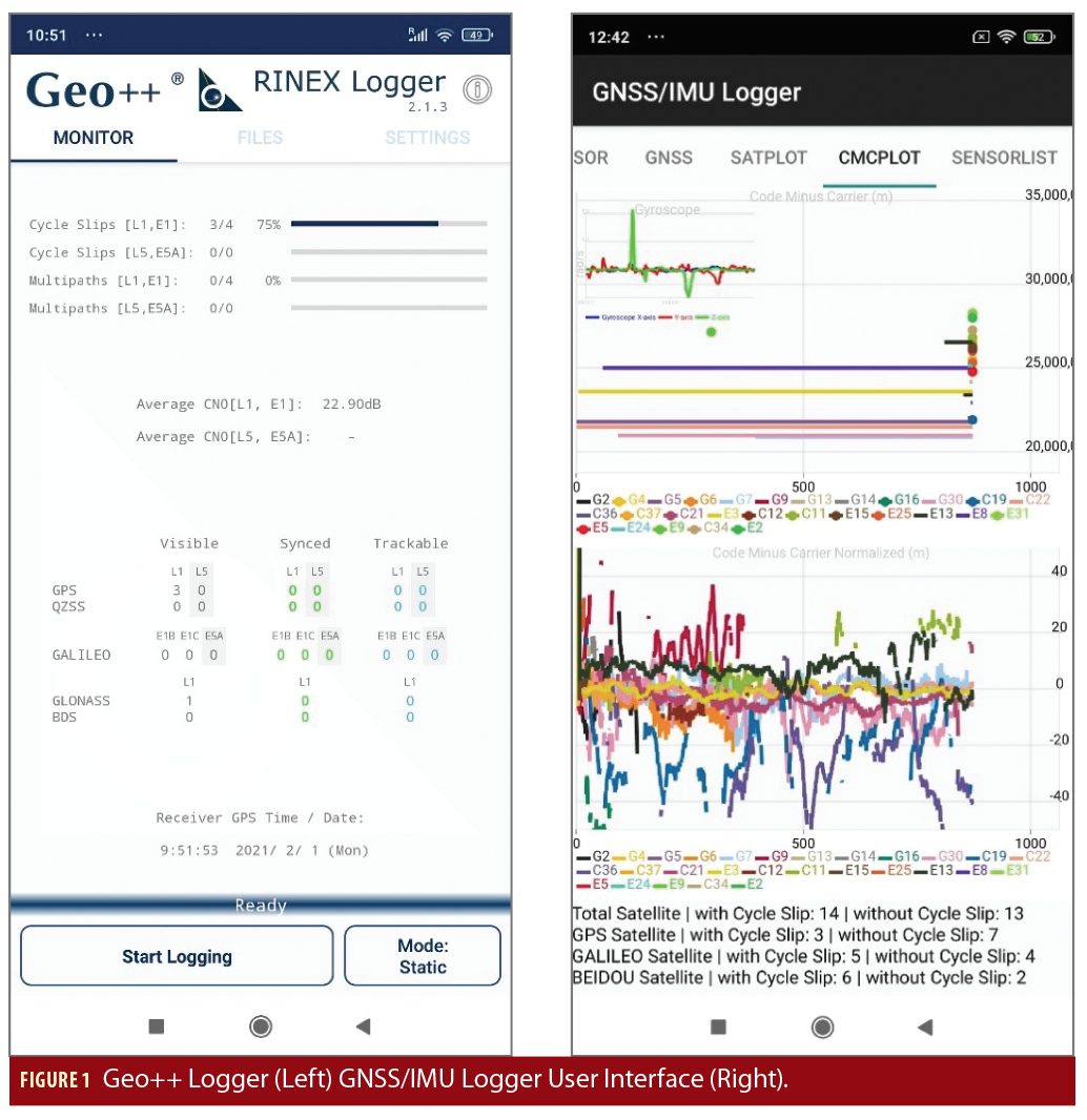
The Geo++ RINEX Logger application was the first application that converted the raw observables from the Android API directly into RINEX files that could be used in established GNSS processing frameworks. It has been optimized with the feedbacks from over a hundred users and now generates meaningful data for a large amount of smartphone models. It has been downloaded more than 10,000 times and is the most widely used logging application for GNSS raw data from phones.
The GNSS/IMU logger app developed at the Institute of Space Research and Space Applications (ISTA-UniBwM) is an extension of the Google logger and exploits the full potential of the APIs available by enabling the user to log GNSS Raw Measurements, GNSS RINEX observation and additionally IMU data (accelerometer and gyroscope) from the smartphone. Additionally, the application has introduced real time code-minus-carrier (CMC) plots to visualize the carrier-phase tracking capability of the smartphone (Figure 1).
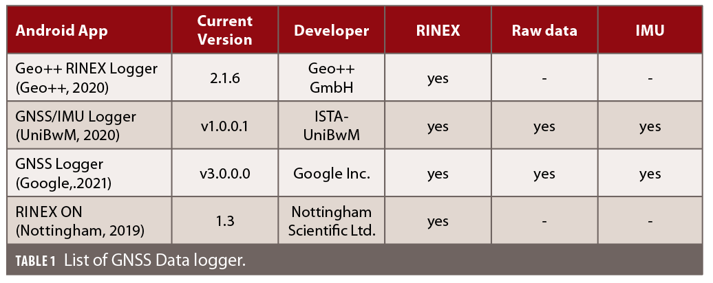
Other parties have developed logging applications (Table 1).
In addition to these applications, there are 200+ applications on the Google Play Store capable of logging GNSS (and partly raw) data. This shows the large and growing interest in this area. Potential applications for precise positioning in smartphones include augmented reality, gaming, and location-based services.
Raw GNSS Measurement Analysis
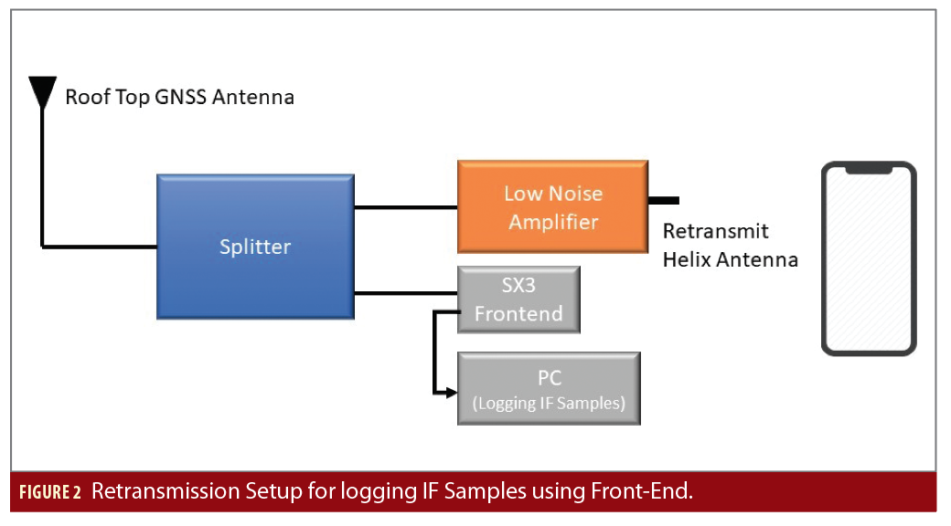
The availability of raw GNSS measurements from the smartphone does not guarantee the feasibility of successful RTK positioning. Due to limited access to the GNSS chip hardware, it is difficult to evaluate the baseband processing performance of the GNSS chip. Instead, we can only analyze the observation data of the smartphone. To overcome this limitation, we try to emulate a smartphone like scenario inside the MuSNAT GNSS Software-Receiver. Developed at UniBwM, MuSNAT is a real-time/post-processing tool capable of performing GNSS/IMU data processing. The concept to emulate the smartphone measurements is to introduce artifacts (code noise, carrier noise, gaps and cycle slips) in high-quality IF samples (logged with SX3 front-end) and to match the quality of this corrupted data to the observation data collected from the smartphone. Figure 2 explains the procedure.
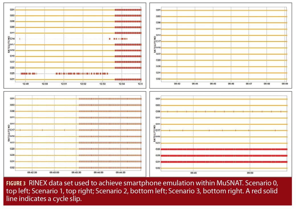
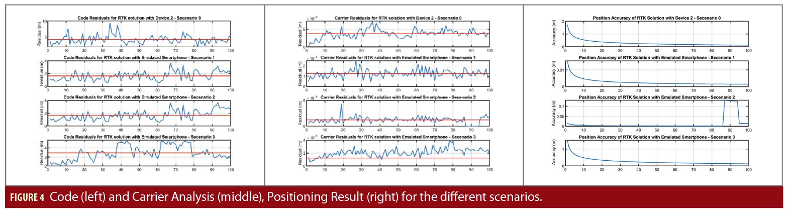
The IF samples recorded with SX3 front-end can be processed with the MuSNAT where the artifacts are added before being passed to the navigation module. Different scenarios generated with logged IF samples and device 2 (discussed in Table 2) were processed with the RTKLIB module inside the MuSNAT (Figure 3).
On analyzing the code and the carrier residuals with the induced artifacts, we were able to achieve similar performance parameters with the smartphone emulation within MuSNAT as measured by device 2. The analysis shows the significance of noise present in the code and carrier measurements and their impact on the positioning performance (Figure 4). The residuals between the measured and predicted code or carrier pseudoranges contain the receiver position error and clock offsets, plus mis-modelling and measurement noise errors. These analyses can thus be helpful to achieve better decorrelation of errors induced due to the mis-modelling.
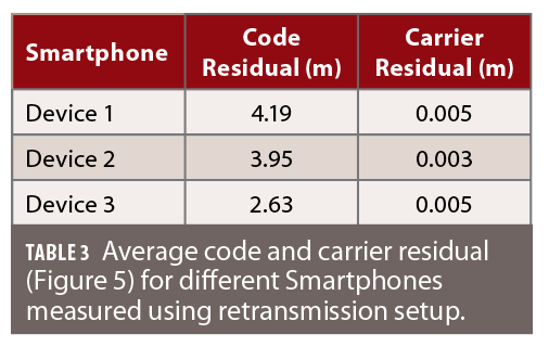
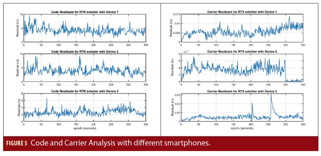
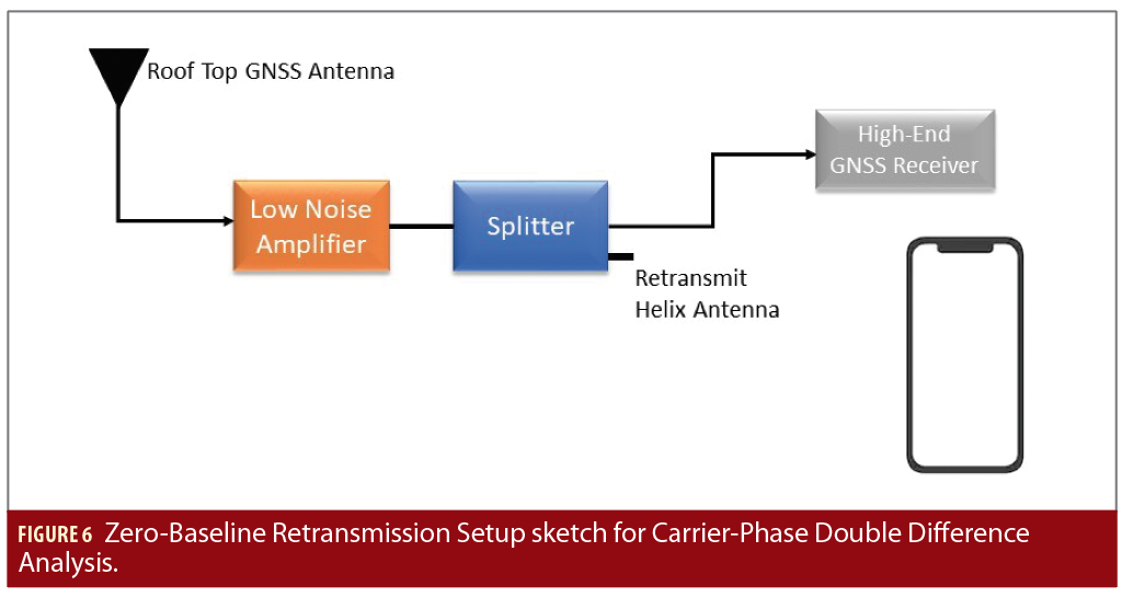
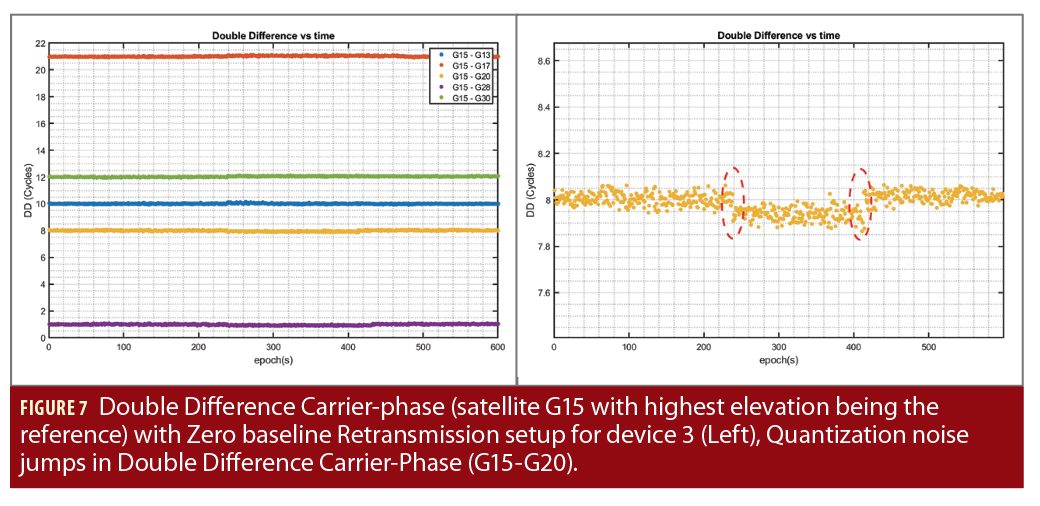
The similar retransmission setup (see Figure 2) of Scenario 0 was then extended to other smartphones. This makes it possible to compare the average code and carrier residual for different smartphones. These results (Figure 5 and Table 3) indicate that device 3 provides a better combination of code and carrier-phase measurements compared to the other two devices under test. However, it is also important to analyze the ambiguity nature of carrier-phase measurements from device 3. Double-difference carrier-phase measurements in a zero-baseline configuration must show an integer nature (within at least a quarter of a cycle) to be fixed correctly. The experimental setup shown in Figure 6was therefore used to analyze the zero-baseline carrier-phase double differences of device 3. The smartphone in this setup is placed near the re-transmitting helix antenna (with amplified signal strength) to ensure no direct signal from the satellite is received within the smartphone.
As can be seen in Figure 7, the double differenced carrier-phase measurements from device 3 with multiple satellites indeed show this integer nature. The experiment was performed multiple times to ensure that behavior is consistent. However, there were small jumps noticed due to the quantization error at the signal processing level Figure 7 (right) (Sharma et al. 2019). These jumps are found also for other satellites in the same epoch. They are small (1/10 of a cycle) in magnitude, and it is questionable if they do significantly impact the RTK solution up-to sub cm level. This experiment shows that under a good quality signal condition with low multipath and high SNR, the internal GNSS chip from the smartphone (device 3) can provide continuous and good quality carrier-phase measurements.
Algorithms and Processing Tools (RTK/PPP)
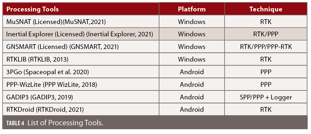
To use the novel dual-frequency raw data output of the smartphones, a highly configurable GNSS processing software is required. An analysis of available open-source processing tools showed that they were not able to adequately handle the poor quality of GNSS observations logged with smartphones. Even in open-sky conditions, the code noise of the smartphone observations ranges from 2–3 m and can be significantly larger in multipath conditions. The open-source GNSS processing framework RTKLIB cannot readily use code pseudoranges with such high code noise as they might be flagged as outliers. The larger number of observations with high code noise makes the code measurements isufficient for SPP position and thus the majority of code and carrier-phase measurements get rejected before being processed with the RTK module. Consequently, other processing options were investigated (Table 4).
With commercially available processing tools such as Inertial Explorer (version 8.70.8722) or GNSMART, the results were more adequate and ambiguity fixing was possible, as long as sufficient quality of observation data was ensured through multipath suppression or retransmission.
Test Results, GNSS Only
Numerous studies show that the multipath effect poses a serious problem on precise positioning with the smartphone. Multipath mitigation methods to be potentially applied can be divided into three categories:
• Before signal processing (through station selection and antenna design)
• During signal processing (through receiver technology)
• After signal processing (through further processing of the observed variables)
None of the methods can eliminate the multipath effect completely, and often a combination of the methods will give the best results.
The approaches related to receiver technology focus on advanced code measurements to suppress the effect of multipath. Due to limited or no access to the IF samples, these techniques cannot be realized by the smartphone app developer. On the other side, techniques for further pre-processing the observation data for multipath reduction are often based on averaging and are already implemented in the wide range of processing tools.
In a series of experiments, we considered the selection of the antenna environment as the easiest and most effective way to minimize the multipath effect. A very common and simple approach to reduce multipath is to optimize the antenna shielding, for example using a round ground plane. The optimal size is 1.5 times the wavelength of the operational frequency. However, the ground plane can only partially shield the multipath signals reflected from the floor. Due to the electrical conductivity of the material, the lower side of the ground plane can trigger surface waves on the upper side of the ground plane. These surface waves can overlap with the direct signal and reach the antenna. To reduce this effect, choke-ring antennas are used in applications where strong multipath reduction is required.
Figure 8 shows a simplified explanation of the effect of the choke-ring: The reflected multipath signal hits the underside of the ground plane and generates a surface wave called primary wave. This primary wave, when reflected from the bottom of one of the choke-ring, generates a secondary wave. Due to the ring depth of a quarter of the wavelength, the secondary waves when reflected have a phase shift of 180-degree with regard to the primary wave and hence attenuate the primary wave before it reaches the antenna element.
Static Measurements
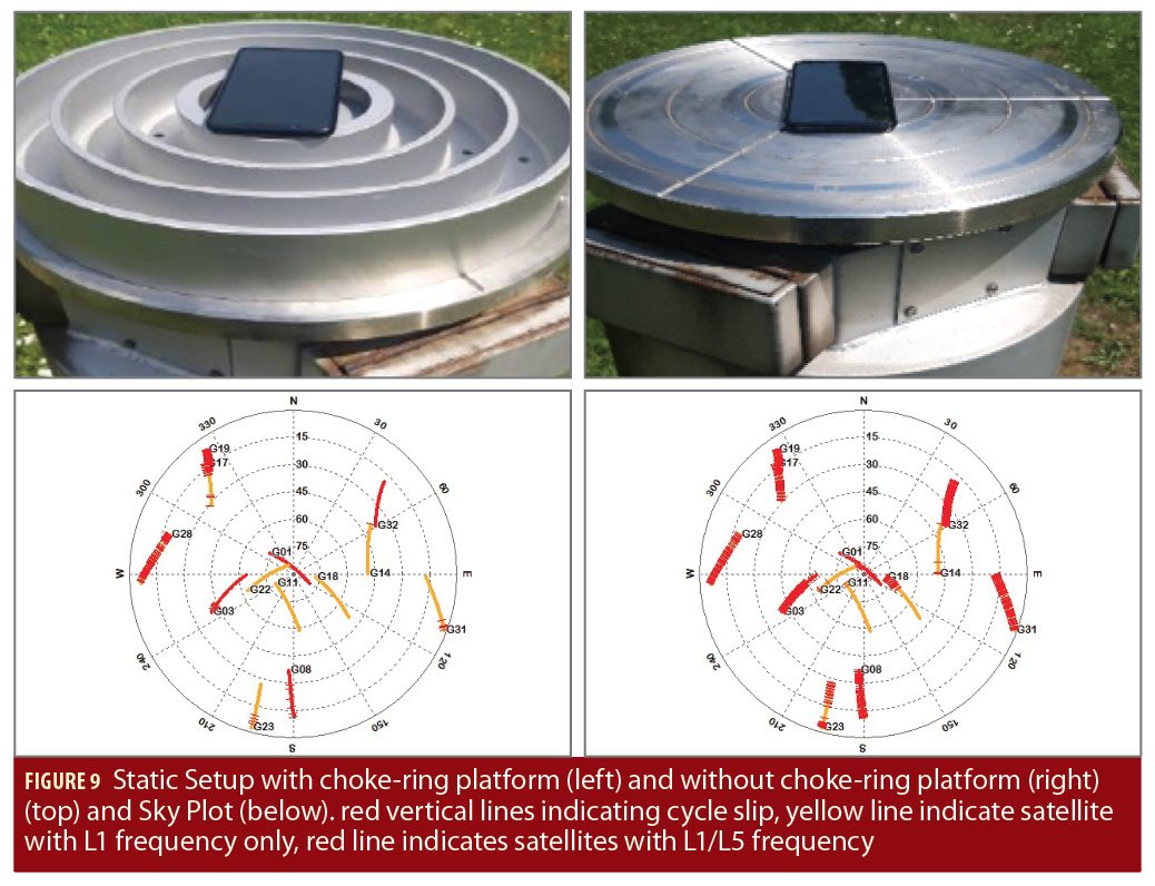
Figure 9 (top) shows the set-up used to analyze the effect of choke-ring platform with smartphone observations. Two phones were placed on two geodetic pillars approx. 20 meters apart. One was placed on a choke-ring platform while the other rested on a metallic ground plane. The coordinates of geodetic pillars are known within mm accuracy. A Trimble R10 integrated GNSS receiver/antenna was placed on another pillar as a reference station. Starting from the raw GNSS data analysis, the quality of data collected with device 3 (with choke-ring platform) improved significantly when compared to the measurements of the phone without choke-ring platform. The sky plot indicates that identical satellites were recorded with both the smartphones. However, the data quality analysis shows that the smartphone with choke-ring platform has better observation data with less cycle slips (Figure 9 bottom-right). Especially for satellites with low elevation, device 3 without choke-ring shows a high amount of cycle slips.
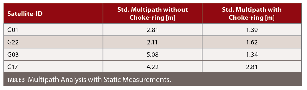
To quantify the multipath suppression with the choke-ring platform, a multipath analysis was done with both data sets. A significant improvement in the multipath was observed for device 3 on the choke-ring platform (Table 5).
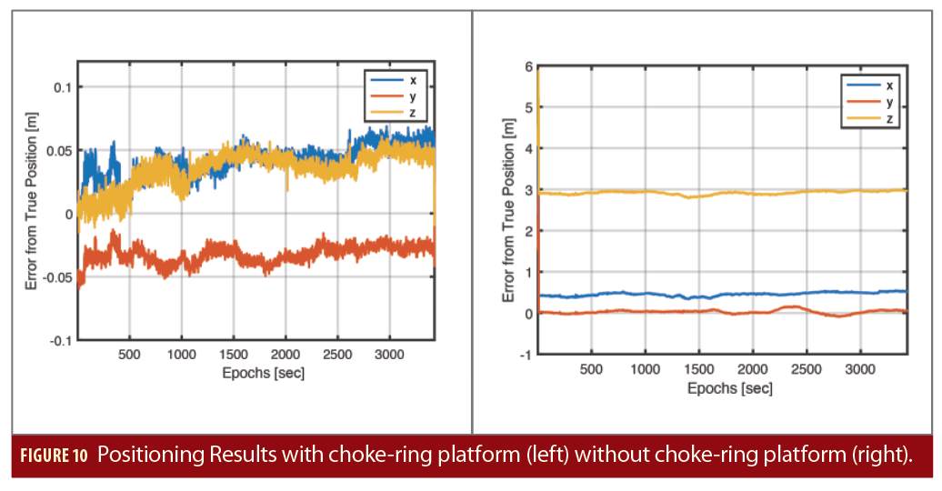
The RTK analysis was performed with Novatel Inertial Explorer using dual frequency GPS and Galileo observations data. The position analysis of GNSS observation data without choke-ring has mean error in the position w.r.t to true coordinates of pillar as 0.462m, 0.0342m and 2.921m in x, y and z (ECEF-frame) respectively due to incorrectly fixed ambiguities. Whereas, with the choke-ring platform, the ambiguities were fixed correctly and the mean error was reduced to 0.041m , 0.032\m and 0.034m respectively (Figure 10) (Sharma et al. 2019).
With the success of the choke-ring experiments in both static and dynamic scenarios, an accuracy of the positioning solution is reached that is sufficient to localize the antenna phase center in the frame of the smartphones.
Antenna Phase Center Estimation
The phase center of the antenna is the (virtual) point where the signals transmitted from the satellites are collected. When a receiver reports a location fix, that location is essentially the phase center of the antenna. For a geodetic quality GNSS antenna, the electrical phase center will vary with the elevation or azimuth of the receiving signal by less than a few millimeters. However, with the smartphone-quality GNSS antenna, this variation is expected to be much higher, as will be demonstrated later.
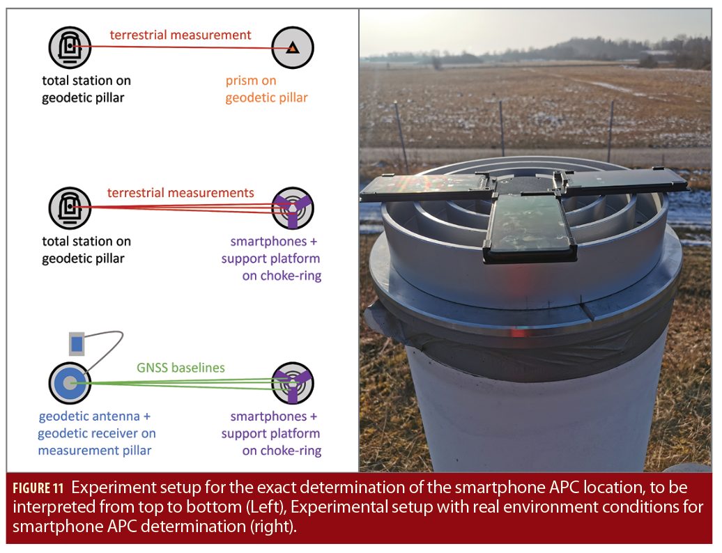
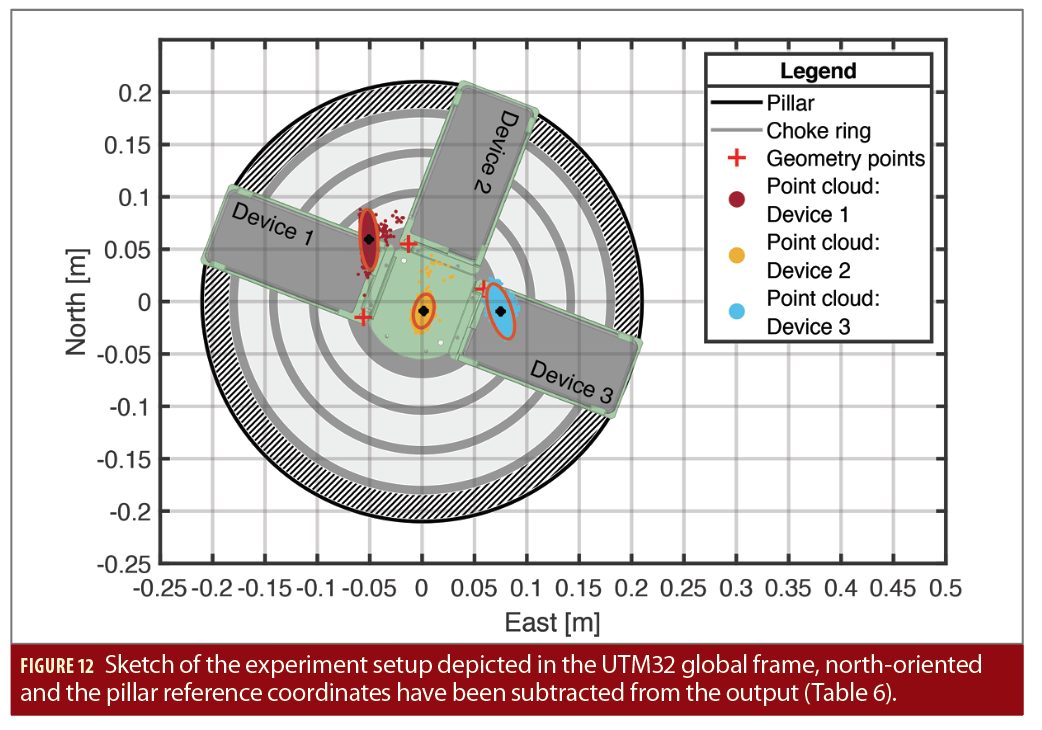
A test setup was planned where the antenna phase center (APC) is estimated relative to the smartphone geometry. The position accuracy of RTK-fix solutions in the (sub) centimeter range (Figure 12) and a precisely known position and orientation of the smartphone in the same geodetic reference frame are considered together. A mounting frame with three attached smartphones (device 3) was placed on a geodetic pillar. A Leica MS60 total station on a neighboring pillar determined the geometry of the smartphones (Figure 11).
Now the exact positions of the mounting frame were measured by means of the total station (Figure 11). Since the position of the center point of the support platform was known, namely that of the measuring pillar on which it is mounted together with the choke-ring, only the rotation relative to this center was missing to determine the absolute location of the mounting frame and the phones. This rotation was determined with the help of corresponding points. The points in the support platform system are very precisely known and were measured in the Cartesian measuring system. The rotation angle was estimated using a simple 2D rotation without translation (the measured points are considered relative to the coordinate of the measuring pillar and thus relative to the center of the support platform).
As a reference antenna with a known position is always required for the RTK solution, a geodetic receiver with a geodetic antenna was installed on another measuring pillar. The baseline between the measuring pillars is approx. 18 meters. Due to the short baseline, fixing of the ambiguities was fast and thus the position converged quickly. Both the raw measurement data from the reference station and from the smartphones were processed in post-processing. The software package Inertial Explorer (version 8.70.8722) from NovAtel was used.
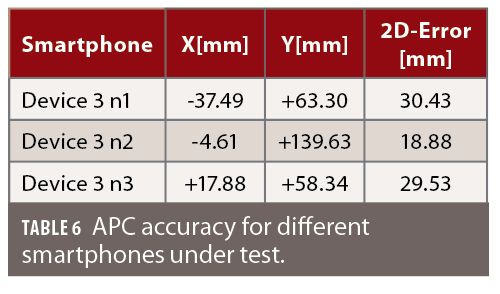
The positions of the fixed RTK solutions relative to the body of the phones show discrepancies among the three phones (Figure 12 and Table 6). While this is a first indication that antenna phase center (APC) might vary considerably between two phones of the same model, further investigation is necessary to rule out other influences as e.g. the satellite constellation during the measurement or interactions between the closely spaced phones. A full phase-center variation (PCV) calibration for a smartphone can support such an analysis.
Smartphone Antenna
Inexpensive GNSS antennas in smartphones are subject to low gain and poor multipath suppression. Mobile devices use an omnidirectional linearly or elliptically polarized antenna due to the unknown orientation of the smartphone. This type of antenna has advantages in terms of received signal strength and the number of received signals, but also makes the antenna very sensitive to multipath effects. This is generally accepted since the design drivers of smartphone antennas are mainly cost and signal availability and not the observation data quality. Furthermore, not only the antenna but other phon e components, like the screen of the device and other transmitting antenna (Wi-Fi, Bluetooth), affect the smartphone antenna, leading to reception pattern irregularities.
Need for PCV Estimation
Multipath and the radiation pattern of the antenna are the main site-dependent error sources of GNSS observations. Smartphone-based code measurements are much noisier than measurements obtained with a geodetic-grade device. Much of this noise is due to multipath that strongly affects the observations. Less noisy code measurement is the prerequisite to exploit full potential of the carrier-phase measurements. As correct ambiguity resolution depends on both the code and the phase measurement quality, highly precise phase measurements are essential to solve ambiguities and achieve fast and precise smartphone-based positioning.
In the double-difference analysis using short-baseline, the only differences between the two receivers are the site-dependent effects related to the type of antenna used and additional possible random biases. Even in an optimal multipath environment, where no ground or wall reflections are possible, some residual phase biases are visible. In this configuration, these residual phase biases are largely due to the radiation pattern of the antenna resulting in PCV.
PCV refer to a mean center (the APC), an imaginary point where the signals are on average received. This center is typically not the Antenna reference point (ARP), which is a well-defined point accessible from outside the antenna. The mean phase center and the geometric offset to the ARP define the phase center offset (PCO), which is the vector between ARP and mean phase center, pointing towards the mean phase center. PCO and PCV are estimated by antenna calibration.
Calibration Technique
The results presented here were obtained using the Geo++ absolute field robot-based calibration of GNSS antennas). Geo++’s approach has these features:
• separation of PCV from multipath;
• absolute PCV, independent from any reference antenna;
• high accuracy and high resolution PCV;
• independent from station and location (e.g. multipath and geographic position);
• field calibration method.
PCV can be expressed as a function of two angles, elevation and azimuth, which gives the position of the source of the signal (i.e. the satellite). Spherical harmonics of degree eight and order five have been used to expand this function. The values of degree and order have been experimentally tested, showing that the obtained resolution was sufficient to model typical geodetic-grade antennas’ disturbances while providing robust calibration results. The PCV is centered to have zero PCV values for zero values of the zenith angle.
Antenna Calibration
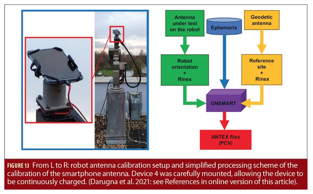
The GNSS antenna of device 4, equipped with a Broadcom BCM47755 dual-frequency (L1/E1-L5/E5a) multi-GNSS chipset, was calibrated. Figure 13 depicts the setup for the smartphone antenna calibration and the simplified dataflow to estimate PCO and PCV. Device 4 was mounted on the robot oriented upright, aligning the smartphone geometrical center with the rotational center of the robot (corresponding to the ARP). The smartphone’s observations collected during the calibration have been post-processed in a multi-frequency GNSS antenna calibration along with GNSS observations from a geodetic reference station using an uncombined observation model. Eventually, PCO and PCV are written into an ANTEX format file with regard to elevation and azimuth.
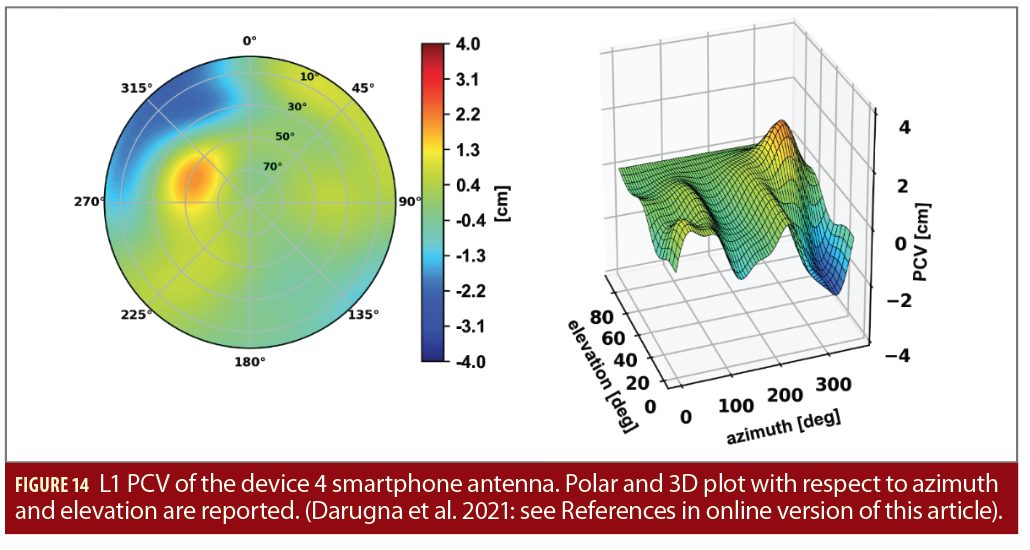
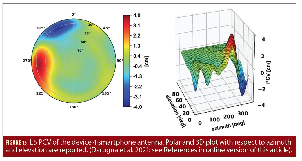
The magnitude of the PCV is shown in Figure 14 and Figure 15 for L1 and L5, respectively. PCV magnitudes up to about 2 cm and 4 cm are observed, with formal STDs (1σ) lower than 1.6 mm. These STDs are related to the variance-covariance matrix of the whole state estimation process. Consequently, they are affected by both the estimation of the parameters of the spherical harmonics and the quality of the observations. Device 4’s PCV is larger than those of a typical rover antenna that typically shows PCV lower than 10 mm, with a smaller than 2 mm variation. The largest magnitudes of the PCV occur for azimuthal angles α∈[270°,360°] for the L1 frequency (Figure 14) and for α∈[230°,360°] for the L5 frequency (Figure 15).
In addition, distinct antenna phase centers have been estimated for L1 and L5, respectively. An analysis of the distribution of the PCV relative to estimated antenna phase center showed that the largest absolute values of PCV are in directions of the major part of the smartphone’s body with respect to the phase center locations. The smartphone components (housing and active electronics), as well as near field effects in that direction, might affect the signal reception, resulting in larger PCV.
The repeatability of the antenna calibration has been assessed by performing twelve distinct antenna calibrations and comparing them to a type mean. In the type mean correction, a rigorous adjustment of the individual PCV spherical harmonic expansions with their complete variance-covariance matrix was executed. A single antenna calibration duration goes from a minimum of six hours to a maximum of 37 hours. The elevation-dependency analysis shows that the agreement between the type mean and the individual calibration is better than 5 mm for elevations higher than 20°. For low elevations, significant discrepancies are visible for the azimuth angle ranges mentioned above. This is uncommon for the antenna calibration and may be attributed to the capability to calibrate the smartphone antenna in those particular elevation and azimuth regions.
Limitations and Evolution
Device 4’s calibration shows estimated PCV much larger than expected for GNSS rover antennas. It also shows a lack of quality in the calibration for limited azimuth-elevation regions. This effect is more pronounced for the L5 frequency, compared to L1.
Different factors might contribute to the larger L5 PCV variation. The tracking performance, in combination with the geometry of the constellation of L5-capable satellites, is not optimal because not all GPS satellites broadcast L5. Secondly, device 4 is equipped with two distinct antennas for L1 and L5; they might be of different quality.
However, considering the type of antenna, the repeatability of the calibration is considered good enough to apply the corrections in a positioning algorithm.
Impact of Antenna Calibration
The PCO and PCV corrections obtained from the calibration of device 4 were applied in the GNSMART algorithm. The PCO can be expressed in terms of PCV; hereafter, we refer to PCV as the total contribution. The concept behind the positioning algorithm is state space modeling (SSM). The setup with open-sky environment has several pillars with known coordinates, and observations of a close (< 10 m) reference station were used. The post-processing algorithm employs an extended Kalman filter (EKF) and an elevation mask of 10 degrees is applied. We achieved ambiguity fixed epochs with at least four satellites fixed to integers successfully, that is, when the ambiguity is fixed to an integer value for two frequencies (i.e., L1 and L5). The ratio test shows values higher than 3.
19 measurements with a good compromise between data quality and satellite geometry were collected. No choke ring multipath shielding was used.
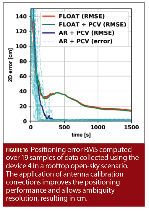
Figure 16 shows the significant impact of the PCV corrections. While for all datasets only float solutions could be achieved without corrections, the antenna corrections improve the float solution by roughly 1 cm. When applying antenna corrections, a 2D RMSE of 1.6 cm and an RMSE of 3.8 cm in the height component can be achieved when the ambiguities are successfully fixed to integers. The time-to-fix ambiguities (TTFA) is less than 3 min in 84% of the cases, while all the 19 samples are fixed in less than 6 min, as shown by the light blue lines. Moreover, a sub-meter 2D solution is obtained in about 1 minute. The relatively long time to reach sub-meter errors can be explained by the large code multipath error. This leads to bad positioning performance during the first epochs, where the influence of the precise phase measurements is comparably small, and noisy code observations dominate the solution.
As only a single smartphone has been calibrated, no conclusion can be drawn regarding the apparent device-to-device discrepancies observed earlier. As an individual calibration of every smartphone is certainly not feasible, it is an important next step to see whether a meaningful calibration can be produced that is valid for all phones of a certain model. Furthermore, the combined application of PCV corrections and multipath shielding with a choke-ring might further improve the RTK performance.
Inertial Aiding
To obtain the full navigation information in mass-market consumer device such as smartphones—3D-position, -velocity and orientation—inertial aiding of the GNSS receiver is beneficial. Therefore MEMS-IMUs standard in current smartphones can be used.
Due to inherent errors, e.g., higher noise level, temperature and vibration sensitivity, the benefit from the MEMS-IMUs is still limited. At this level, this sensor can be integrated with the dual-frequency GNSS observation, i.e., code-phase and carrier-phase, to exploit INS/GNSS-coupling, especially tight coupling, where a reliable satellite measurement can provide feedback to the IMU signal to calibrate its bias and scale factor error. In return, the error-compensated IMU observations can support the GNSS receiver during short satellite outages, duty cycle gaps or high multipath scenarios to propagate the navigation state with less accuracy degradation. The IMU could also contribute to the detection of cycle slips and ambiguity resolution. Despite all these advantages, very tedious calibration, such as 3-axis rotation table and climate chamber, and (stochastic) modelling procedures are needed to consider all error comports in the estimator filter. Nevertheless, the accuracy of the sensor itself will not improve, since the low-cost mass-market MEMS devices have a physical limitation that cannot be exceeded.
A recently introduced micro gyroscope sensor (5mm diameter) based on fused-silica precision shell integrating (PSI) principle (wineglass gyro) with 0.0062°/√hr ARW and 0.027 °/hr is at least 1,000 times more sensitive than a conventional MEMS. These noise characteristics allow these devices to be categorized as (near) navigation grade IMU. Unfortunately, this technology is still in the prototyping phase and has not yet entered mass-market manufacturing. If widely adopted, they would revolutionize smartphones’ dead-reckoning capability.
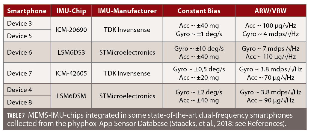
As thes MEMS-IMUs built into smartphone largely come from a few large companies, it is possible that smartphone manufacturers employ the same MEMS chip, as shown in Table 7. Sometimes, they change chip supplier from one generation to the next.
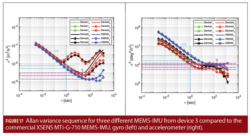
In Figure 17, the stochastic modelling of the ICM-20690 IMU-chip from three different dual-frequency smartphones of device 3 is shown. The assessment of the random processes available in both gyroscope and accelerometer signal is made by the mean Allan-Variance sequence. Additionally, for comparison, another commercial MEMS-IMU from Xsens is also shown.
According to the IEEE Standard Specification (IEEE Std 952-1997, 2018), the smartphone accelerometer axes contain white noise (-1/2 slope), bias instability (flat region with 0 slope) and correlated noise (hill shape between cluster time = 1 s and 100 s). In comparison to the Xsens IMU, the axes of the device 3 accelerometer random processes are not identical, especially the z-axis, which reflects the exact behavior of correlated noise that can be modeled as 1st-order Gauss-Markov (GM) process. Unexpectedly, all three smartphones accelerometers show the same atypical behavior in the z-axis. This can be explained by the manufacturing process related to the MEMS-IMU technology. A three-axis MEMS accelerometer chip can sense accelerations as a reaction of the force applied to the chip housing. The change in movement is equivalent to the change of capacitance between the moving structures of the chip. To guarantee the sensitivity in all three directions, i.e., x, y and z, two proof masses are available, namely a XY-axis proof mass and Z-axis proof mass that detect the in-plane and the out-of-plane accelerations respectively. But, due to the limited space in a smartphone, the manufacturers usually tend to use a flat structure for the MEMS chip which results in different shapes for the XY and Z proof mass. The Xsens-IMU exhibits a similar noise figure in all three-axes.
As depicted in Figure 17, the Allan variance diagram for the gyroscopes shows the same noise fluctuation for all axes and reveals at the same time less noise affecting the device 3-IMUs. Both angle random walk (ARW) and bias instability (BI) values of all three smartphones gyros are smaller than those of the commercial Xsens device. For example, in the case of device 3 gyro, the ARW parameters are smaller than 0.31 deg/h while the Xsens indicates amplitudes between 0.49 deg/h and 0.55 deg/h.
GNSS/INS Processing
The availability of the GNSS/IMU logger paved the path for first trials of GNSS/INS combined processing. The GNSS data was logged with 1Hz, whereas the IMU data was logged using pre-defined rate constants “SENSOR_DELAY_FASTEST” provided by the Android system (approximately 300 Hz). The GNSS observation data can be logged in RINEX 3.03 format and IMU data is logged in ASCII format. For a successful GNSS/INS combined processing, both GNSS and IMU data should be synchronized to the same time scale. However, the GNSS data logged using GNSS/IMU logger is in GPS time and the IMU data is in the internal Android UNIX time that is synchronized to UTC via the mobile phone network.
GNSS/IMU combined processing can therefore be performed without any dedicated synchronization mechanism, as the offset between GPS time and UTC time is known and can be applied. The synchronization accuracy might be limited, and future update of the GNSS/IMU logger will consider use of Android internal counters.
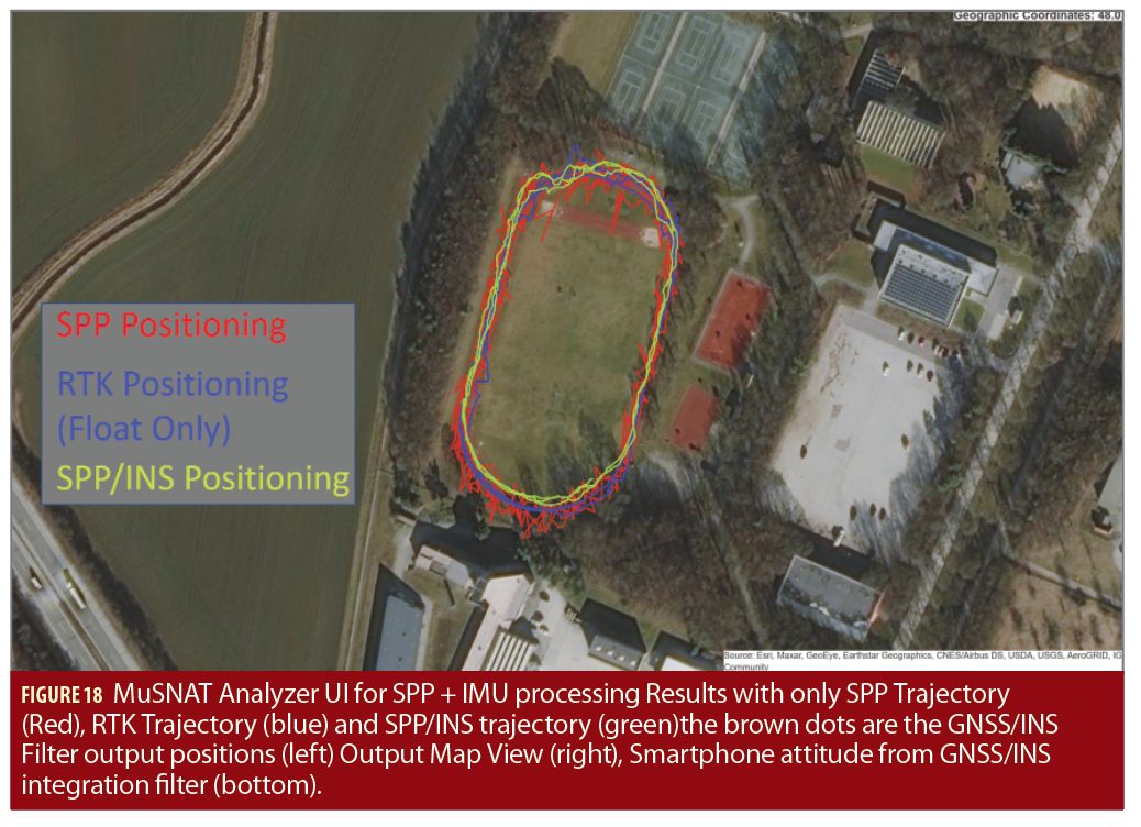
In the first data set, the smartphone was held loosely in hand while walking around the track inside the UniBwM Campus. The smartphone logged GNSS and IMU data simultaneously using GNSS/INS Logger. The data was processed with the MUSNAT (integrated GNSS/INS Kalman Filter) as shown in Figure 18. For the preliminary results, the SPP/INS integration was performed to compare SPP/INS trajectory with SPP and RTK solution. Due to the poor carrier-phase measurement quality, the RTK solutions were float only. The obtained attitude is correct, but the positioning results show room for further improvement by integrated IMU data with the RTK position solution.
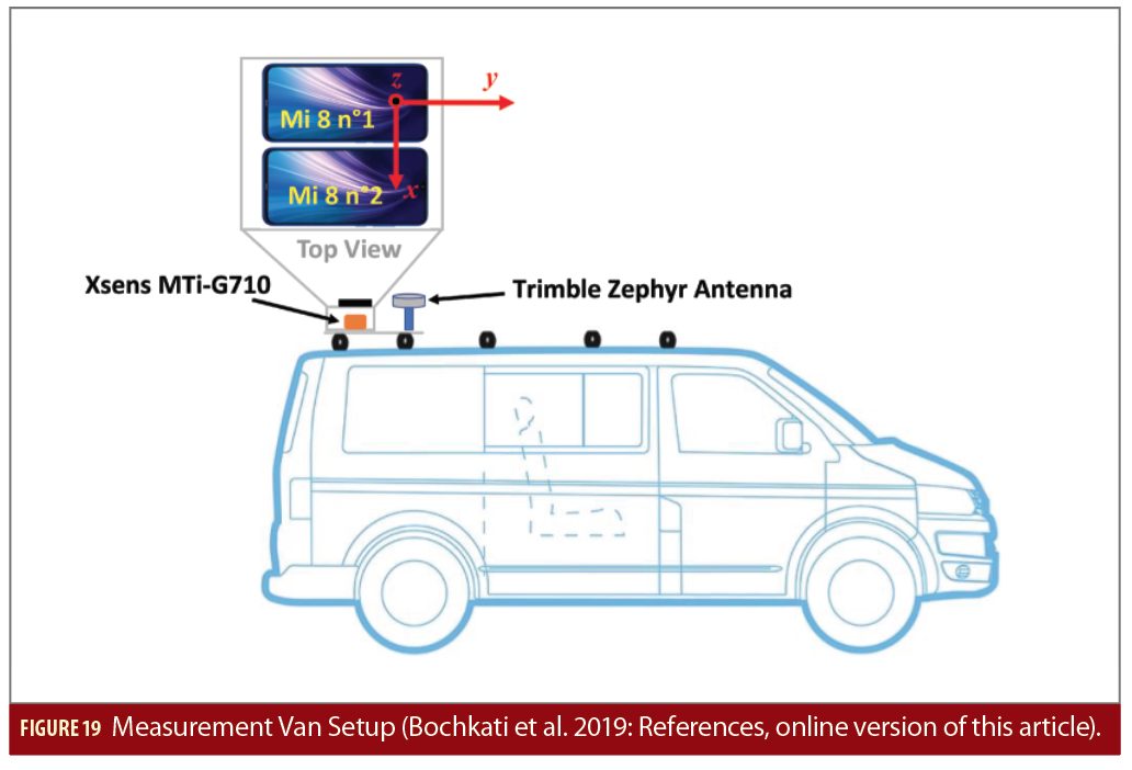
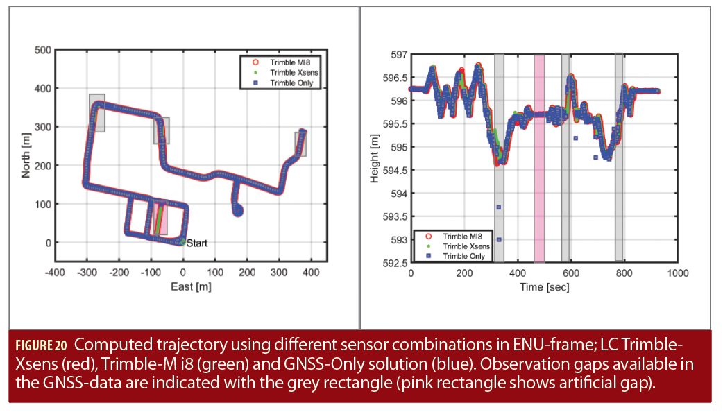
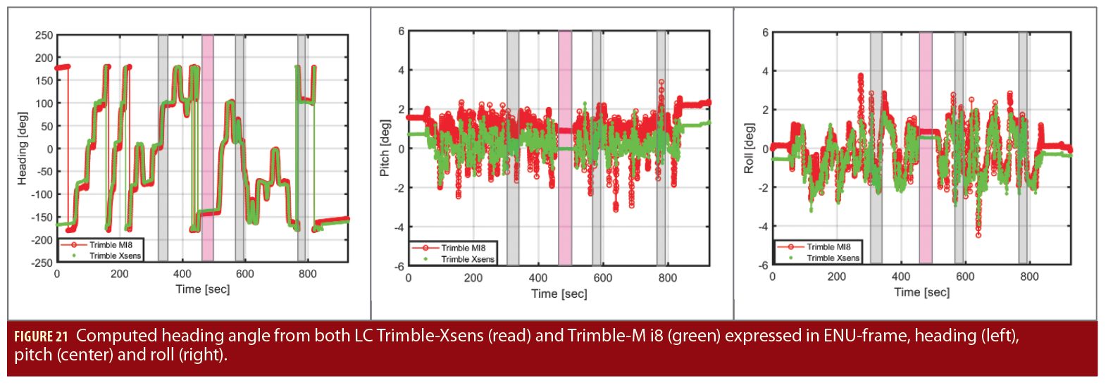
To assess performance of the smartphone IMU in the context of GNSS/INS integration in a more focused way, in another experiment, two device 3 were fastened on the roof of a measurement van (see Figure 19). A high-end geodetic receiver (Trimble NetR9) and antenna (Trimble Zephyr 2) were fixed close to both devices to provide a reference trajectory. A commercial grade MEMS-IMU (Xsens MTi-G-710) was also mounted directly underneath to assess the quality of the TDK-Invensense IMU employed by the device 3. A local GNSS reference station located around 200 meters from the test track was running simultaneously to allow RTK-positioning. The trajectory environment contains both open-sky segments as well parts with buildings (elevation about 50 degrees) and dense. Complete satellite signal blockage is indicated in Figure 20 with grey rectangles. In addition, an artificial GNSS data gap was introduced.
The recorded GNSS/IMU data were loosely coupled (LC) in different combinations, using Inertial Explorer. Considering the Trimble NetR9-Xsens trajectory as reference, we can see that the device 3 IMU has a good performance, especially in term of the estimated attitude angles, i.e., heading, roll and pitch (Figure 21). At the beginning of the trajectory, the kinematic alignment delivers slightly different roll and pitch angles between the Xsens and the device 3 which is around 1 deg. This can be explained by the different noise standard deviation of the accelerometer axes, as depicted in Figure 17. The estimated heading information using both IMUs with the Trimble receiver are very closed to each other. Even though after introducing an artificial gap of about 20 seconds (pink rectangles) both IMUs propagated the navigation solution correctly.
Therefore, in this demonstration, the LC with the smartphone MEMS-IMU not only increases the availability of the positioning solution, but a smoothing behavior can also be achieved, if the LC-Filter, i.e. GNSS- and IMU-observation, can be tuned properly.
Conclusion and Outlook
Despite the latest innovations, there are still key limiting factors to the full scale use of smartphones in high-precision applications. The availability of dual-frequency GPS/Galileo observations definitely enables ambiguity fixing but works only under a controlled condition or otherwise in a partly unreliable way. The mixture of frequent cycle slips, biases and high noise/multipath remains a challenge for the processing algorithms.
The analysis revealed that the extremely poor multipath suppression of a smartphone antenna together with the high PCV is a major impediment for cm-level accuracy. Precise localization of the antenna phase center within the smartphone, better understanding of antenna parameters like gain pattern (i.e. directivity of the smartphone GNSS antenna), the PCV and analysis of the impact of human body interaction on gain and PCV still need to be addressed. Antenna PCV corrections can be applied during moving operations taking care of the smartphone’s attitude by using the internal IMU. The requirements concerning the precision of the attitude are correlated with the PCV pattern itself. Non-homogeneous antenna patterns with sudden peaks would require more precise knowledge of the attitude than antennas with homogeneous patterns.
For the analyzed case, the minimum requirement for the attitude precision would be 5°, i.e., as large as the calibration azimuthal resolution. Even smallest carrier-phase biases at chip level should be absent for cm-level positioning to not further stress the RTK error budget. The ability to track the carrier-phase continuously in the strong multipath (including fading) conditions seems to be one of the most difficult requirements for the smartphone GNSS chip. Additionally, getting access to the correlator values for understanding multipath mitigation at signal-processing level might open new perspectives for development.
In contrast to the GNSS antenna, the smartphone internal IMU demonstrates a surprisingly good performance. We clearly see a need for elaborated IMU error models, but once they are obtained, the IMU will precisely aid the navigation solution even without relying on a dedicated motion model. This may in future algorithms include cycle slip repair or bridging of data gaps due to GNSS chip duty cycling.
Current RTK or PPP processing software packages seem not optimized to process the poor quality of smartphone raw measurements. Investigations on optimal pre-processing of the observation data and improved cycle-slip handling could therefore be beneficial. IMU aid cycle slip detection and correction with a tightly coupling fusion strategy and the development of extended sensor calibration models for smartphones could also be addressed.
Manufacturers
HTC Nexus 9, Device 1. Samsung S8, Device 2. Xiaomi MI8, Device 3. Huawei Mate20X, Device 4. HUAWEI P30, Device 5. Xiaomi Mi 9, Device 6. Xiaomi Mi 9T Pro, Device 7. HUAWEI P40 Pro, Device 8.
Authors

Himanshu Sharma is a research associate at the Institute of Space Technology and Space Applications (ISTA). He received his M.Sc. in the communications and signal processing from TU Ilmenau.

Mohamed Bochkati is a research associate at ISTA. He holds a Master’s degree in Geodesy and Geoinformation from Technical University Munich.

Christian Lichtenberger has an M.Sc. in geodesy & geoinformation from the Technical University Munich. He is a research associate at ISTA.

Thomas Pany is a professor at the Universität der Bundeswehr München where he leads the satellite navigation unit of ISTA.

Francesco Darugna holds a doctorate from the Leibniz University of Hannover, Germany. He is a post-doc fellow at the University of Padova.

Jannes B. Wübbena is s managing director at Geo++ GmbH. He performed his PhD thesis work on novel atomic clocks at the German National Metrology Laboratory (PTB) in Brunswick. .


