
An on-board spoofing detection unit collects metrics from the GNSS signal processing chain and provides a real-time indication if the receiver is under spoofing attack. Test results from several spoofing scenarios are based on GNSS hardware simulations, repeaters and software-defined radios.
By Ali Broumadan, Sandy Kennedy and John Schleppe
Recent spoofing activities of different types reported in China and the Middle East provide actual evidence of position and time distortion in civilian applications.
This article describes a wide range of spoofing attack scenarios and their features, as well as the results in testing against these scenarios. Spoofing can occur by changing relative signal power, synchronizing signals to those of authentic ones, and capitalizing on the availability of authentic signals. To combat spoofing, various detection methods are being developed by using metrics at different stages of the signal processing within a GNSS receiver with a single antenna input. These detection units are tested in different spoofing and non-spoofing scenarios to analyze their detection and false alarm probabilities. Both hardware-simulated spoofing and software-based spoofing methods with HackRF were used to evaluate the detection performance. Several tests in static and dynamic conditions across different environments evaluate the false alarm probability of these detectors. The processing results show how effective these spoofing detection metrics are in identifying spoofing signals.
Classifying Spoofing Attacks
Regardless of the source of a spoofing attack, attacks can be classified as non-overlapped, overlapped, or by its relative power.
Non-overlapped. In this case the code and carrier phase of the spoofing signals are not synchronized with the authentic signals. The correlation peaks of the spoofing and authentic signals do not overlap. During a cold start, if the spoofing power is higher than that of the authentic signals, the acquisition engine may be deceived depending on the receiver search strategy. When a signal is in the tracking stage, the other regions of the cross-ambiguity function are invisible to the receiver. Therefore, a higher power spoofing signal might not affect the tracking procedure if the delays or Doppler frequencies are not aligned.
Overlapped. In a more sophisticated attack, a spoofer can synchronize its code phase and Doppler frequency with those of the authentic ones. In an overlapped attack, the correlation peaks of spoofing and authentic signals combine to constructively or destructively alter the shape of the correlation peak. This type of spoofing attack might be generated by a receiver-based spoofing generator where the spoofer knows the current time,observable satellites,location and parameters of the target receiver. Correct detection of an overlapped spoofing attack is challenging as the distortions caused by spoofing signals appear similar to multipath errors.
Relative Power. The power behind the spoofing attack is an essential feature in order to deceive the target receiver. The relative power level of spoofing signals with respect to that of authentic signals can highly impact the effectiveness and error limit of spoofing interference. Identifying spoofing attacks based on their relative power is difficult as it requires information about the spoofer’s propagation channel, the antenna gain pattern and its orientation.
Detection Metrics
Each metric uses a specific feature of an attack as described before.
INPUT POWER ANALYSIS. One method of spoofing is to first jam the receiver, then provide the false signals. To detect this kind of attack, users monitor the input power to detect additional power injected by interference signals. This can be done by monitoring the gain of the automatic-gain-control (AGC) module.
STRUCTURAL POWER CONTENT ANALYSIS. This method takes advantage of the cyclo-stationarity of GNSS signals in order to detect excessive amount of structured signal power (such as spreading codes) in the received sample set. The received baseband samples are first filtered within the GNSS signal bandwidth, and then multiplied by their delayed version in order to remove the Doppler effect.The resulting signal has a line spectrum generated by multiplication of cyclo-stationary signals. In the next stage, the signal and noise components are then filtered by suitably designed comb filters. A detection test statistic is calculated based on the filter outputs and compared to a threshold in order to detect an attack.
EFFECTIVE C/N0. This common signal monitoring metric is available in most commercial receivers.
The upper limit of a GNSS signal power level is known for a given test setup. For a given receiver, an upper limit for the C/N0 value can be defined. An abnormally high C/N0 value can be an indication of a spoofing attack. However, it’s important to note that jamming signals can also affect the effective C/N0 values by increasing the noise floor.
SQM. The interaction between authentic and spoofing signals during overlapped attacks causes distortion on the shape of the correlation peak. Signal quality monitoring tests focus on this feature in order to detect any asymmetric, abnormally sharp or elevated correlation peaks. SQM metrics were originally designed to monitor the correlation peak quality affected by multipath signals, and are widely used in high integrity applications. Users have seen success applying these metrics when identifying spoofing attacks.
CLOCK MONITORING. This metric detects spoofing signals from a single-antenna source based on the position solution of a moving receiver. In a single-antenna spoofing scenario, all fake PRNs are transmitted from the same antenna. As a result, the signals all experience a common delay that is due to the propagation distance between spoofer antenna and the target antenna/receiver. The relative motion between the spoofer and receiver antennas creates a variable bias in the clock bias estimates of a receiver that can can be used to identify an attack.
Implemented Detector
A real-time spoofing detection unit, employing a selection of the most effective detection metrics, was implemented on a generation of high-precision receivers. In the testing presented herein, the detection unit monitors GPS L1 C/A observations. The detection metric outputs are fed to an onboard central spoofing detection unit, which provides a decision as to whether the receiver is under a spoofing attack every two seconds. The main feature of the spoofing detection unit is to both reduce false detection probability due to the presence of jamming and multipath signals, and also detect the spoofing attack with high confidence. The detection thresholds for individual metrics are based on an acceptable false alarm probability under various scenarios.
Experimental Results
The spoofing detection unit outputs either zero or one, where one indicates an attack is detected.
Hardware Simulator Test
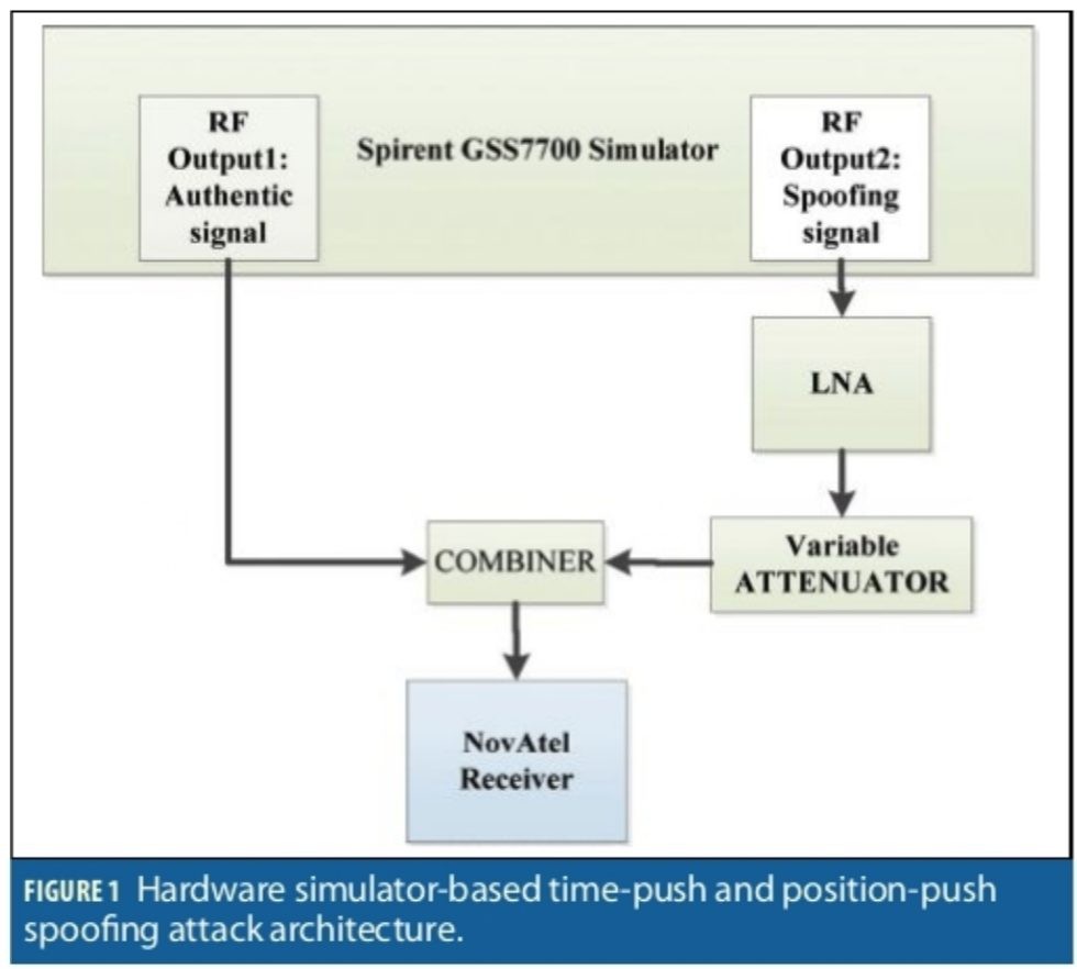
A hardware simulator generating GPS L1C/A signals was used in this test. This simulator generates two RF outputs at two distinct locations. This feature was used to simulate an authentic and a spoofed scenario. RF output1 and RF output2 were assigned to authentic and spoofing signals respectively. For this test, the receiver was configured to track GPS L1C/A only. The block diagram of the scenario is shown in Figure 1.
The authentic signals were directly connected to an RF combiner, while the spoofing signals generated by the simulator were passed through a low noise amplifier (LNA) and a variable attenuator adjusting the power level against the authentic source. Both RF outputs generated the same PRNs. With this simulator, the user can adjust the clock bias and clock drift of each individual RF output. This feature generates two synchronized signals referring to the same position with different range bias and drift. The range bias and drift for all the PRNs from each RF output is the same. This generated both non-overlapped and sweep spoofing attacks.
For the non-overlapped case (position-push attack), the clock bias of the spoofing signals was set to 6 µs. In this case, the correlation peaks of the authentic and spoofing signals were separated by about 6 GPS L1C/A chips and did not overlap. In the sweep test, the clock bias and drift of the spoofing signals were changed to simulate a sweep spoofing attack (time-push and position-push attack). For ease of comparison, static and dynamic positions were allocated to the authentic and spoofing cases respectively. The spoofed position was moving on a circle and the authentic location was set at the centre of the circle.
Sweep Test (Overlapped)
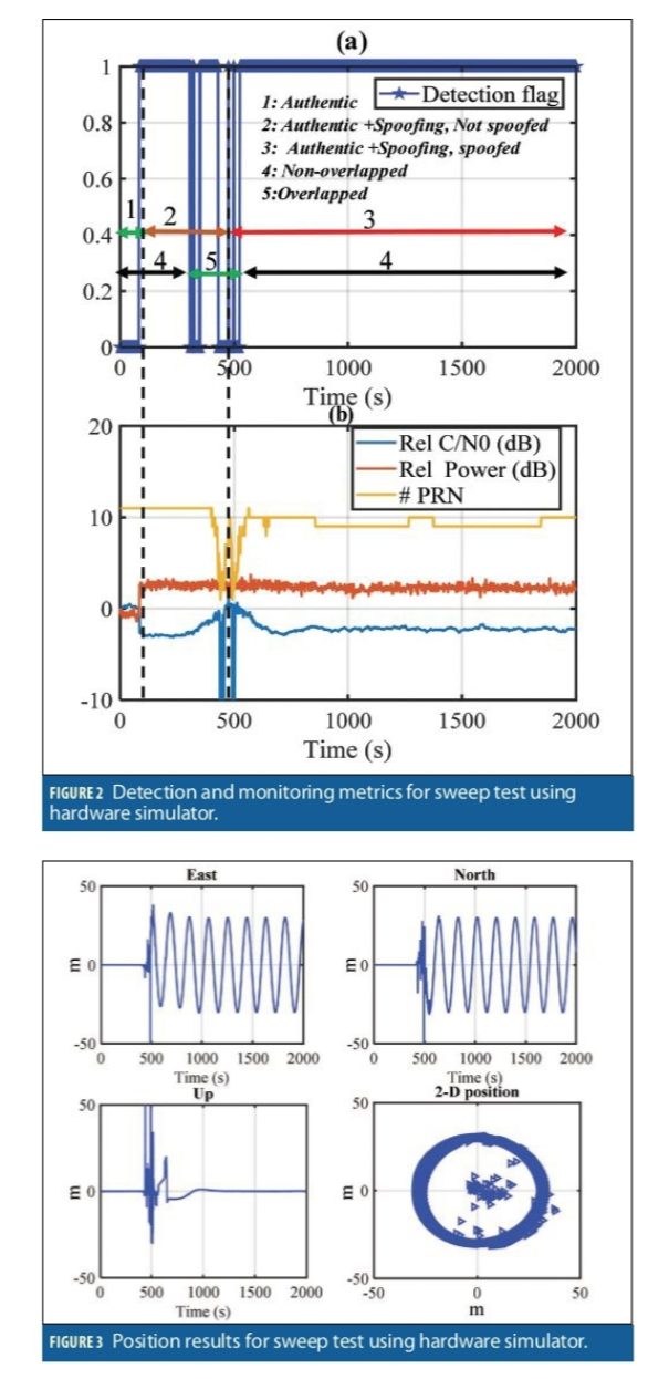
This sweep test included a matched-power attack where the spoofing power advantage was within a couple of dBs. During the first 50 seconds, the receiver was only exposed to the authentic signals. Then, the spoofing signals with slightly power advantage were added to the scenario. The spoofing clock bias and clock drift was set to 6 µs and 0.007 µs/s relative to the authentic signals. The correlation peaks at the beginning were not overlapped. However, the clock drift caused all the spoofing PRNs to sweep through the authentic signals and grab the tracking correlators of the receiver and eventually spoof the receiver position. (Recall that this receiver was tracking only GPS L1 C/A signals for this test).
Figure 2b shows relative input power (relative to the authentic signal), relative average C/N0 (relative to the C/N0 at the beginning of the test) and the number of tracked signals for this data set. Figure 2a shows the spoofing detection results as the attack progresses.
At 50 seconds from the start of the scenario, the spoofing attack was initiated. The spoofing attack is detected as soon as the spoofing signals were present (50s). The attack caused a 3 dB jump in the input power and consequently reduction in average C/N0 as shown in Figure 2b. Between 50 seconds and 450 seconds, the spoofing attack acted as a wideband jammer. In this period, the receiver tracked the authentic signals and the estimated position was the authentic position. As shown by the relative C/N0 and number of tracked PRNs in Figure 2b, the authentic and spoofing signals began to interact at the 450-550 second mark. During the spoofing/authentic interaction (470-530s) the detection flag went on and off. During this time, the receiver lost signals tracking and there were insufficient observations available for detection. The spoofing detection stayed on for the rest of the test as shown in Figure 2a.
Figure 3 shows the East, North, Up and 2D horizontal position of the receiver in the sweep test. After about 500 seconds from the beginning of the data set, the position was spoofed and the receiver position started moving in a circle. As shown, the spoofing attack was reliably detected during an attack where the spoofing power advantage is within couple of dBs.
Variable Power Spoofing (Jam/Spoof)
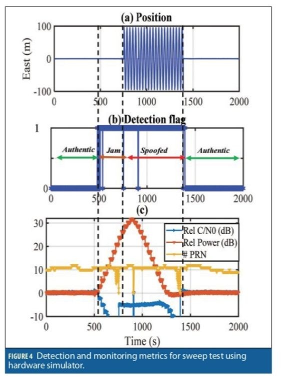
In the next test, the hardware simulator forced the receiver to stop tracking the authentic signals. This model simulates a high-power spoofer scenario. The clock bias of the spoofing signals was set to 6 µs and the clock drift at 0. This ensures that the correlation peaks are not overlapped so that the only way to attack the receiver is to jam first and then spoof. Figure 4c shows the relative input power, relative average C/N0 and the number of tracked signals during the test. Figure 4b shows the spoofing detection flag for this scenario. The spoofing attack was detected as soon as the spoofing power began affecting the noise floor at about 500 seconds, before the receiver position was spoofed at 750 seconds, and continued until the receiver stopped tracking the spoofing signals. Again, recall that only GPS L1 C/A signals were used in this test.
The receiver started tracking the authentic signals while the spoofing power gradually increased by about 30 dB and then decreased. The spoofing attack started to have a noticeable effect on relative C/N0 and input power after 500 seconds. From 500 to 750 seconds, the spoofing power was increased by about 20 dB and eventually masked the authentic signals. In this period, the spoofer acted as a wideband jammer. At about 770 seconds the receiver lost tracking of all authentic PRNs and shortly after started tracking the spoofing signals while the spoofing power was increasing.
As shown in Figure 4a, the receiver position was spoofed at about 780 seconds when it began moving in a circular pattern with a radius of 100 meters. Between 780 seconds and 1250 seconds, the spoofing power increased and also decreased, but the average C/N0 stayed constant. This pattern continued until about 1250 seconds when the average C/N0 began dropping. This is when the authentic signal power started affecting the receiver noise floor. From 1250 to 1450 seconds, the receiver tracked the spoofing signals while the spoofing power was decreased. At about 1450 seconds, the receiver lost its lock of spoofing signals, and started tracking the authentic signals again.
Repeater Spoofing Attacks (Jam/Spoof)
In this section the results of a repeater/meaconing attack are provided. To this end, two rooftop antennas separated by about 30 meters were used as the authentic and spoofing sources. The test configuration is shown in Figure 5. The authentic antenna was directly connected to a three-way RF combiner. The spoofing signals were passed through an active module that was delaying and filtering the signals. The delay module output only GPS L1/L2 signals, and delayed the signal by about 150 µs. The signals then fed to a 40 dB LNA, to a variable attenuator, and then connected to the combiner.
The output of the combiner fed two receivers, one with GPS L1 C/A configuration, and the other with multi-frequency multi-constellation configuration tracking all available signals from GPS, GLONASS, Galileo and BeiDou satellites. This setup was designed to test the benefit of multiple constellations and frequencies in withstanding a spoofing attack.
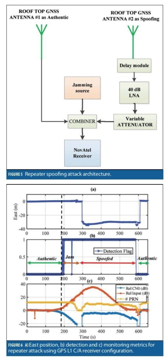
GPS L1 C/A receiver:
Figure 6 shows the results of the GPS L1 C/A only receiver. The receiver was exposed to authentic signals for about 180 seconds, and then the spoofing power was gradually increased. The relative input power and C/N0 and the number of tracked GPS L1 C/A signals are shown in Figure 6c. The spoofing power was gradually increased, which eventually increased the noise floor by about 35 dB and then decreased. Figure 6b shows the spoofing detection flag. The spoofing detection module detected the spoofing activity at about 190 seconds as soon as the noise floor was affected (before the receiver position was spoofed) and stayed on until the end of the attack at about 600 seconds. The receiver lost all tracking channels at about 280 seconds and began tracking the spoofing signals at about 300 seconds. During the signal outage (280-300s), when there was not enough observation available, the receiver continuously provided the last estimated time and position. At 300 seconds the receiver position was spoofed as shown in Figure 6a until 600 seconds when the receiver lost tracking of spoofing signals and began tracking authentic signals at about 610 seconds. The East position results are shown in Figure 6a.
Multi-constellation Multi-frequency receiver
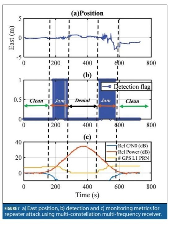
Figure 7 shows the results of a similar test with the OEM7 configured as a multi-constellation multi-frequency receiver. The spoofing power started affecting the receiver noise floor at about 120 seconds. At 300 seconds, the receiver lost tracking of all authentic GPS L1C/A signals (also jammed other signals sharing bandwidth with GPS L1,including Galileo E1) while the noise floor was increased by 20 dB. During the attack, the receiver was continuously tracking authentic signals from other frequencies and constellations including GPS L5 and Galileo E5. As such, these built-in integrity checks did not allow the receiver to track the spoofing signals. Hence, during the spoofing attack (300-500s), there were not any GPS L1 C/A measurements as shown in Figure 7c, and the attack caused denial of service for GPS L1 C/A signals. As shown in Figure 7a, the receiver position was not spoofed during the attack, and the receiver provided continuous authentic position solutions. Figure 7b shows the detection flag. The detector is active during 180-280 seconds and 500-560 seconds when GPS L1 C/A measurements were available and successfully detects the attack when measurements were available.
Start-up Under Spoofing Attack (High power)
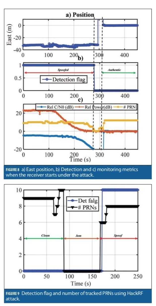
This test was designed to observe detection performance while the receiver is starting up during an attack. The receiver was exposed to a spoofing attack directly after a power cycle. The same spoofing scenario in Figure 7 (repeater attack) was used. The receiver configuration was GPS L1 C/A and started with a high-power spoofing attack with about 20 dB higher power compared to the authentic signals. The relative input power and C/N0 compared to the authentic scenario is shown Figure 8c. During the first 120 seconds, the spoofing power stayed constant and 20 dB higher than the authentic one. Then the spoofing power was gradually decreased. At about 280 seconds the receiver lost tracking of spoofing signals. At 300 seconds, the receiver began tracking the authentic PRNs. The spoofing detection flag is shown in Figure 8b. The attack was detected successfully during the entire scenario. Figure 8a shows the East position of the receiver during the attack. As shown, the receiver position was spoofed initially, then jumped to the authentic position when the spoofing attack disappeared at 300 seconds.
HackRF Test:
In this section, the results of spoofing attack using a HackRF are shown. GPS L1 C/A signals were generated with HackRF with a 6 MHz bandwidth. The spoofer used the actual and most recent ephemeris data to generate the signals. Figure 9 shows the detection flag (as 0 and 10, rather than 0 and 1) and the number of tracked PRNs. During the first 90 seconds, the receiver was exposed to authentic signals from a stationary antenna, then was attacked by a wideband jammer for about 90 seconds. The spoofing attack began at 170 seconds at the beginning of the data. In Figure 9, the spoofing detection flag is set as soon as the spoofing attack began.
Jamming Test
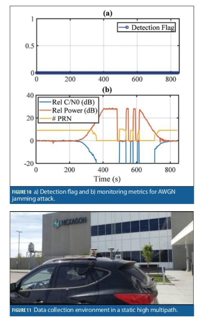
The authentic rooftop antenna was combined with a 4 MHz AWGN jammer centered at the GPS L1 C/A frequency. The input power and average relative C/N0 are shown Figure 10b. The jammer power was gradually increased by about 30 dB. The receiver lost tracking at about 350 seconds. Then the jamming power turned on and off to demonstrate the spoofing detection performance in the presence of intermittent jammer. At that point, the jamming power was gradually decreased. The spoofing detection results are shown in Figure 10a. As shown, there were no incidents of false spoofing detection for this scenario.
Static and Dynamic Tests
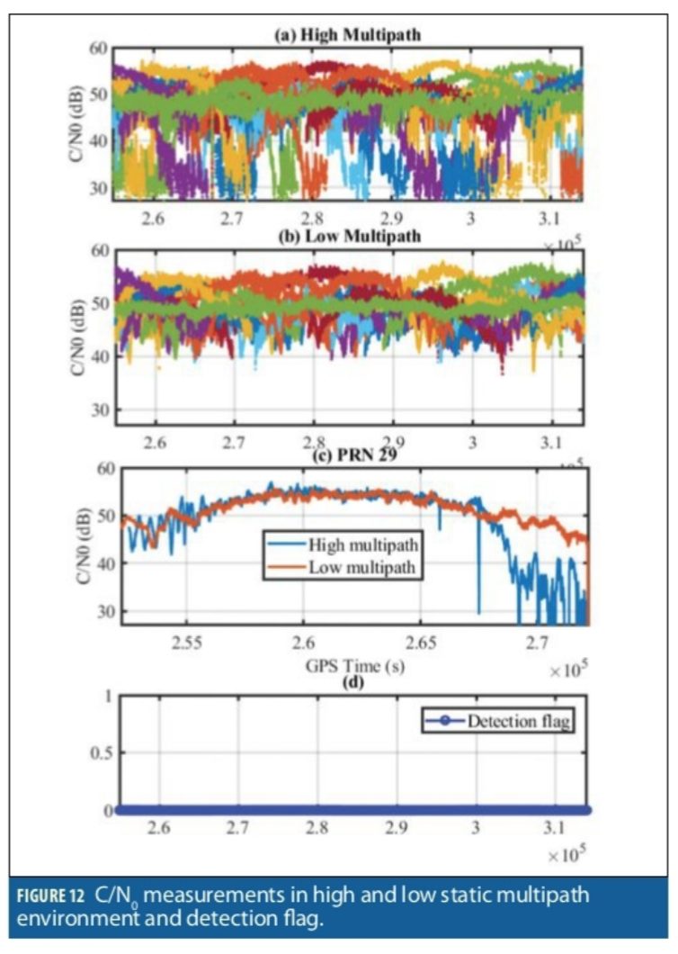
To investigate the false spoofing detection probability, several data sets were collected in different environments, specifically static high multipath as shown in Figure 11, and dynamic suburban and urban environments in Calgary. The received signal strength measured by C/N0 is used to characterize the harshness of the wireless propagation channel. In multipath and fading environments, signal strength fluctuations are caused by signal reflection, refraction and blockage, which disrupts the receiver tracking functionality and GNSS measurements. Figure 12a shows C/N0 measurements in static high multipath location. For comparison, Figure 12b shows the C/N0 measurements of an open sky antenna located nearby on the rooftop of the building visible in Figure 11. Figure 12c compares the C/N0 of PRN 29 at both locations. The C/N0 measurements of the high multipath antenna are clearly affected.
Figure 12d shows the spoofing detection flag for this test and no spoofing detection is reported.
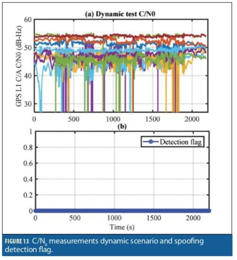
Figure 13 shows the C/N0 measurements for GPS L1 C/A collected in while driving a route through suburban and urban environments around Calgary.
As seen in the results, the receiver antenna was subject to signal blockage and multipath from GNSS obstacles like road signs, underpasses, trees and buildings ranging from single story residential homes to multiple story office towers. These obstructions caused signal power fluctuation and several events of tracking lock loss. The spoofing detection flag is shown in Figure 13b. The spoofing detection module did not detect any spoofing activities during this test.
Summary and Conclusions
The processing results show how effective the spoofing detection metrics are when identifying spoofing signals across a wide range of scenarios. The results demonstrate that the attack can be identified as soon as the spoofing signals are present, and even before the receiver position is spoofed. The results of attacking GPS L1 and L2 frequencies using different receiver configurations showed that the multi-frequency multi-constellation receiver position and time were immune to the attack, whereas the GPS L1-only receiver position was spoofed. Nevertheless, the detector successfully identified the attack in both cases. Experimental results in jamming, high multipath, static and kinematic environments were used to analyze the false alarm probability of the detector. No false detection was observed during the tests under clean no-spoofing conditions. Reliable, correct spoofing detection is the first step towards safe and effective mitigation, either by user actions or receiver operation.
Authors
Ali Broumadan received his Ph.D. degree from the Geomatics Engineering department of University of Calgary. Currently, he leads the Resilient GNSS team at the Hexagon Autonomy and Positioning research group. He has been involved in several projects focusing on signal processing in GNSS receivers.
Sandy Kennedy leads the research group at Hexagon A&P as Vice President of Innovation. Previously, she was responsible for developing the OEM7 generation of GNSS receivers, and retains a keen interest in GNSS resiliency. She completed a M.Sc. in Geomatics Engineering at the University of Calgary, specializing in GNSS/INS integration.
John Schleppe was a research fellow and group manager at NovAtel until his passing in January 2020. He completed his B.Sc. and M.Sc in Geomatics Engineering at the University of Calgary.
Manufacturers
The real-time spoofing detection unit was implemented on the NovAtel OEM7 generation of receivers, which were used for the tests described here. A Spirent GSS 7700 simulator was also used.


