Integrity for Navigation Land Users (INLU) addresses the difficult task of adapting air-based position integrity solutions to land-based activities such as vehicle and rail travel.
An end-to-end simulation is presented using the Positioning and Integrity Performance Evaluator (PIPE). The simulation includes side by side comparison of a vehicle path in the presence of spoofing as evaluated by the authors’ Generalized Pseudo Bayesian 1 (GPB1) algorithm and a snapshot least squares algorithm. Every field application has its own operational conditions and resulting requirements with respect to accuracy, availability, and continuity for systems that provide position, velocity, and time (PVT) measurements. For example, Global Satellite Navigation Systems (GNSS) found application for certain approach procedures in commercial aviation due to the advent of Satellite Based Augmentation Systems (SBAS) that provide additional integrity information to GNSS receivers. GNSS reception environments for aircraft are nominally clear-sky conditions and the combination of GNSS, SBAS, and advanced processing techniques like Receiver Autonomous Integrity Monitoring (RAIM) yields the required compliance for probabilities of detecting malfunctions and times-to-alert.
Providing absolute, three-dimensional positions on Earth together with well-proven and cost-efficient receiver technologies predestines GNSS equipment to enter the emerging markets of land-based users such as autonomous vehicles and the railway industry. However, since the operational conditions of these applications differ dramatically from those present in the aviation world, PVT measurements with integrity based on GNSS as previously developed cannot be translated directly to land-based users.
This article presents the scope and an application example of the Integrity for Navigation Land Users (INLU) research study as part of the European Space Agency’s Technology Research Program (see Additional Resources, J. Wendel et alia (2016a)) that develops techniques to provide PVT solutions to land-based users within defined integrity bounds.
The environments in which landbased users move impose reception limitations on GNSS receivers. In cities, the GNSS signals are frequently blocked and reflected by buildings, structures, and other traffic, for example. The same is true for railway applications. Here, GNSS blockages arise from features ranging from shunting yards over railway stations to rides through cuttings and tunnels.
To be able to create new satellite navigation technologies that provide PVT information with integrity and solutions for high-precision positioning even under difficult conditions, a well-suited end-to-end simulation tool is required. End-to-end means that realistic signals from complete satellite constellations can be generated which take, for example, transmitter and receiver antenna characteristics, atmospheric and local wave propagation mechanisms, receiver dynamics, and other distorting effects into account.
Often such end-to-end simulations are performed using a radio frequency constellation simulator (RFCS) and hardware GNSS receivers. A number of commercial off-the-shelf solutions are available for each of these items. However, for the development of said algorithms, it is more efficient to be able to use pure software or hybrid hardware/ software solutions. This allows for a much higher frequency for the development-integration-test cycles of a project.
To respond to INLU’s requirements and to meet today’s needs of GNSS endto- end simulations, Airbus Defense and Space has been developing the Positioning and Integrity Performance Evaluator (PIPE) as a research activity since 2012. Beyond INLU, PIPE found applications for the development of novel tracking (F. M. Schubert et alia (2014a); F. M. Schubert et alia (2015)) and channel model research (I. Gulie et alia; F. M Schubert et alia (2016)), to name a few examples.
The article’s organization follows the high-level procedure of getting results from an end-to-end simulation run using PIPE. We first describe the scenario definition in terms of user trajectory, satellite constellation, and propagation channel conditions. Next, the configuration of the simulated receiver is reported with methods for acquisition and tracking of GNSS signals and computation of the PVT solutions. An example is then given that reports a filter bank approach developed during the INLU project. It is used for mitigating the influence a spoofer has on the receiver’s performance.
Scenario Generation
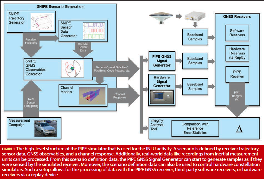
Figure 1 reports the general structure of end-to-end GNSS simulations that can be performed using PIPE. PIPE consists of three groups of programs: tools for digital signal processing (DSP), a GNSS scenario and constellation simulator, and a GNSS receiver. PIPE’s DSP provides classical signal chain simulations consisting of a signal source, one or multiple signal processors, and a signal sink. Among other programs, PIPE includes GNSS signal generators, filters, up- and down-converters, and interference signal generators.
PIPE’s scenario and constellation simulator programs are able to generate user trajectories, satellite positions for given times and orbits, and the propagation channel response based on multipath components. As this group of scenario-related programs differs from the DPS programs, they are called SNIPE tools — short for Scenarios for Navigation and Integrity Performance Evaluation. INLU also requires the possibility to process real-world signals. Signal sources for the PIPE receiver can be sampled signals as sensed by antennas, the PIPE software GNSS signal generator, or samples recorded from an RFCS’s output.
PIPE accommodates INLU’s diverse requirements by a modular approach of signal chain simulations: Certain software elements of the chain can be replaced by hardware components. Additionally, interfaces to front-end sampling and replay devices are available.
The following subsections describe the creation of the user’s trajectory, the simulation of a satellite constellation as well as the processing of the response stemming from a propagation channel model.
Trajectory Generation
The first step in the scenario generation process is the creation of the user’s trajectory. This trajectory serves as input for the generation of GNSS observations, as well as further sensor data like odometers, inertial sensors, baro-altimeters, and magnetometers. The challenge hereby is to produce consistent dynamics data. When the accelerations and angular rates provided by the trajectory generator are used for the generation of inertial sensor data assuming an ideal inertial measurement unit, the output of an ideally initialized strapdown algorithm must match the original trajectory exactly, even after longer simulation times. This is achieved in the trajectory generator first by producing desired positions and attitudes over time. Then, a strapdown algorithm together with a flight control-like algorithm is applied. From the small offsets between desired positions and attitudes and the strapdown state, accelerations and angular rates are generated, which are provided to the strapdown algorithm in the next epoch and drive these offsets to zero.
Constellation Simulation
From the trajectory generation, the GNSS antenna positions and velocities also can be calculated at equidistant points in time. For each of these points, the constellation simulation needs to calculate the corresponding satellite positions and velocities based on RINEX files. The trajectory time scale defines the times of reception of the satellite signals. In order to calculate the satellite positions and velocities, the times of transmission at the satellite need to be determined. This is achieved by approximating the satellite orbit in a time interval of T=0.1 seconds by a straight line, which is accurate to the sub-millimeter level. Denoting the time of reception with t0, the satellite position pS at the time of transmission t0–t can be expressed as
![]()
It must now be considered that the ECEF frame is rotating. The ephemeris describes the satellite position in the ECEF frame at the point in time for which a satellite position is calculated. In order to express the satellite position at t0–T in the ECEF frame that is valid at t0, the rotation of the ECEF frame in the time interval T needs to be considered:
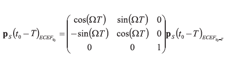
In the following, pS(t0–T) always refers to the satellite position at t0–T, expressed in the ECEF frame at t0. In order to determine the time of flight of the satellite signal t, the equation relating the range between satellite position at time of transmission, pS(t0–t), and antenna position at time of reception, pA(t0), is used:
![]()
Here, c denotes the speed of light. Inserting the linear approximation of the satellite orbit and squaring the equation leads to
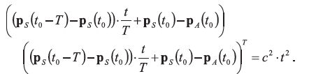
This is a quadratic equation that can be solved for the time of flight, t. Consequently, the satellite position at time of transmission, pS(t0–T), in coordinates of the ECEF frame at time of reception, t0, is obtained. The carrier phase, code phase, and Doppler measurements obtained at t0 can then be generated using appropriate error models.
Propagation Channel Models
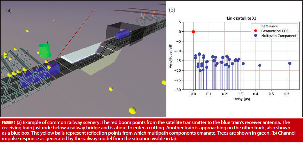
The reception conditions for land-based users are impacted to a large extent by multipath propagation caused by objects and structures in the receiver’s vicinity. Moreover, in urban areas, signals are often blocked and diffracted by buildings and trees. State-of-the-art multipath propagation models reproduce these effects and generate channel impulse responses (CIR) at a given rate dependent on the receiver’s dynamics. CIRs contain components that reflect the complex amplitude and delay of line-of-sight as well as multipath components.
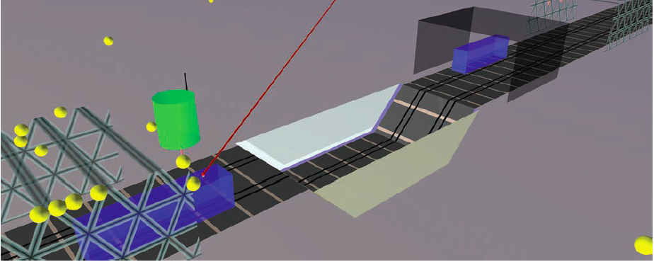
PIPE’s interface to a channel response generated by a multipath propagation model is given by the Channel Data Exchange format (CDX) (see CDX – Channel Data Exchange Library in Additional Resources). The PIPE GNSS signal generator can read the channel impulse response for every time step from a CDX file and generate the corresponding multipath components with their respective delays and complex amplitudes in the output signal. This allows for the usage of various channel models for INLU. Within the project, the model recommended by ITU-R P.681 for urban environments was used. Additionally, this model was extended for railway applications during a research activity (I. Gulie et alia). Figure 2 shows the visualization of a common railway scenery.
The INLU project also requires the generation of RF signals by hardware constellation simulators using the mentioned channel models. As these models produce more multipath components than a common hardware constellation simulator can re-produce, a component count reduction step is required. In INLU, a method based on F. M. Schubert et alia (2014b) is applied.
Land User Receiver Prototype
The PIPE GNSS Receiver used to run the INLU simulations is not only able to process samples, bit-true mode in INLU terms, it has also a semi-analytic operation mode that calculates correlation results based on pre-computed autocorrelation functions of GNSS signals. The semi-analytic mode runs multiple times faster than the bit-true mode and allows for simulation of long runs. The scenario input data as well as the receiver’s implementations for items such as tracking loops and PVT computation are identical for both modes.
Tracking Algorithms
In addition to standard tracking methods like Early-Minus-Late and Bump Jumping, the PIPE receiver offers a number of state-of the-art tracking techniques, such as the Double Delta Correlator, Kalman filter-based methods, Double Estimator, and Maximum Likelihood-based methods, such as Multipath Estimating DLL and Vision Correlator. All these methods are scrutinized during the INLU project. For the following example, the Astrium Correlator (AC) is applied which offers robustness against locks to false side peaks while tracking binary offset carrier (BOC) signals (F. M. Schubert et alia (2014a)). For signal tracking, the AC uses a BOC’s signal subcarrier to exploit the higher accuracy that can be achieved when tracking such signals to the legacy binary phase shift keying (BPSK) signals. At the same time, the AC checks if it tracks the BOC signal’s central peak via the observation of the BPSK envelope of the signal. If a lock to a side peak is detected, the tracker is commanded to switch its tracking point toward the correct main peak.
Integrity Algorithms ARAIM Tailored to the Railway Environment
The main objective of INLU was the development of integrity algorithms tailored to the land user environment. The following integrity concept for railway users was developed as an INLU scenario.
Providing integrity for train position information is a major technical challenge due to the small integrity risk that is tolerated in railway applications. In the current implementation of the European Rail Traffic Management System (ERTMS), the train position is propagated using odometry, and corrected when a balise group is reached. A balise is a transponder that provides an absolute location reference to the on-board unit of the train, allowing the train to locate itself within a movement authority. GNSS positioning is being considered in the context of the ERTMS evolution for the realization of a virtual balise concept, where GNSS is used for the detection of virtual balises. The approach of virtualizing the balise transmission system aims to reduce the cost of trackside infrastructure associated with the installation and maintenance of physical balises, while minimizing changes to the existing system and maximizing interoperability. Consequentially, requirements on the integrity of position information provided by the GNSS receiver are very stringent.
The integrity concept within INLU can be seen as a step towards a realization of the virtual balise function. A block diagram of this concept is shown in Figure 3. The integrity algorithm processes pseudorange measurements from a GNSS receiver, measurements from odometry, and exploits information contained in a map database. It consists of two major building blocks, a module for pseudorange measurement rejection, and the integrity module that calculates the projection level.
The measurement rejection module consists of a Kalman filter that integrates the odometer measurements with the track database and the pseudoranges from the GNSS receiver. The a priori position available from this filter is used to calculate the Mahalanobis distance of each pseudorange, and upon excess of a pre-defined threshold for the Mahalano-bis distance, the respective pseudorange is rejected.
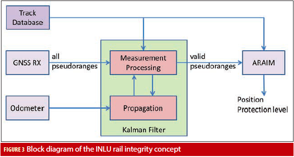
The integrity module calculating the projection levels uses the pseudoranges that passed the Mahalanobis distance check in the measurement rejection module as well as information from the track database. In consequence, the position solution provided by the integrity module is independent of the odometry, in the sense that the odometer readings do not enter in the position calculation. For projection level calculation, a solution separation approach is used. In solution separation RAIM, the spread of subset position solutions with respect to the full set position solution is assessed. Subset position solutions are obtained by excluding subsets of satellites from the position calculation. Thus, the number of satellites that are excluded must reflect the number of simultaneous faults that need to be considered. The probability that a higher number of simultaneous faults occurs is very low, but might still be included in the integrity risk budgeting.
The major difference between a conventional solution separation RAIM outlined above and the proposed integrity concept is that from the pseudoranges which have passed the measurement rejection module, a three dimensional position solution is not calculated, but rather a GNSSbased odometer distance results. Using this GNSS-based odometer distance, a three-dimensional position solution can then be obtained from the track database. Consequently, for the calculation of protection levels, the spread of GNSS-based odometer distances is assessed, not the spread of position solutions. Obviously, calculating a GNSSbased odometer distance instead of a three dimensional position reduces the number of unknowns from four to two, which means that with two pseudoranges only, a solution can be obtained. More details of this integrity algorithm are given by J. Wendel et alia (2016b).
Filter Bank for GNSS and INS Integrity
Within the INLU project, integrate navigation systems were also addressed, in which the software GNSS receiver is combined with inertial sensors in loose, tight, and ultra-tight coupling architectures. Such architectures do not allow for the calculation of protection levels using ARAIM algorithms because these require that full set and subset position solutions are calculated using snapshot least squares.
A variety of techniques can be found in literature which aim at the provision of integrity for integrated navigation systems. Batch processing approaches re-formulate the GNSS/INS data fusion as a least squares problem, which then allows us to apply RAIM or ARAIM techniques (M. Joerger and B. Pervan). Another option is to use a filter bank. Each elemental filter in the filter bank is robust with respect to a specific fault.
In the simplest case, an elemental filter does not process the measurements of a specific satellite. In case the measurements of this satellite are faulty, this filter is not affected. This also avoids the need for a pseudorange fault model which is an advantage because such a model is in general rarely available. Examples of filter bank approaches can be found in (M. Brenner; J. Diesel and S. Luu), with the basic concept illustrated in Figure 4 with three filters only. Obviously,
a real GNSS/INS filter bank contains many more filters. For the single fault case, the number of elemental filters matches the number of satellites from which measurements are available, with possibly an additional elemental filter assuming no faults are added. Each of the elemental filters propagates its state and covariance matrix forward in time using the measurements provided by an inertial measurement unit (IMU).
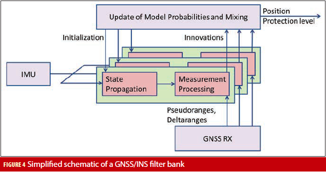
When pseudorange and delta range measurements become available, they are processed by each elemental filter except for those the elemental filter assumes to be faulty. Hereby, the model probabilities are also updated. For each elemental filter, the model probabilities represent the likelihood that the assumptions of the filter are correct, i.e., that the satellites that the elemental filter assumes to be faulty actually are faulty. This update is based on the ability of the filter to predict measurements. The better the elemental filter pseudorange and delta range predictions match the actually available measurements, the higher the model probability.
After the measurement processing, a mixing step is executed. In this mixing step, each elemental filter is reinitialized with a new state estimate and covariance matrix, which are calculated from the model probabilities, state estimates, and covariance matrices of all elemental filters. It is important to note that for the most widely used filter bank, i.e., the Interacting Multiple Model (IMM) filter bank, all elemental filters are initialized differently. Therefore, state and covariance of each elemental filter must be propagated separately, even if all elemental filters assume the same system model.
The main drawback of such a filter bank is the huge computational load. In most integrated navigation systems, most of the computational cost is spent in the propagation step. The reason for this is that the state and covariance matrices of the navigation filter must be propagated with a reasonable update rate in order to cope with the vehicle’s dynamics. For example, in a GNSS/INS system, several propagation steps are performed (for example, every 5 milliseconds when the inertial sensors provide measurements) before one measurement step takes place, i.e., every second when a typical GNSS receiver provides measurements. With the values given in this example, 200 propagation steps are performed before one measurement step is performed.
Within the INLU project, a GNSS/INS integrity algorithm based on a Generalized Pseudo-Bayesian 1 (GPB1) filter bank was developed. The only difference between an IMM and a GPB1 filter bank is the mixing step. For the GPB1 filter bank, the mixing step initializes all elemental filters identically. As all the elemental filters have the same system model — namely the error propagation equations of inertial navigation plus additional states to estimate the inertial sensor biases — the use of a GPB1 filter bank allows INLU to perform propagation steps with one elemental filter only, instead of with each elemental filter of the filter bank. Then, when GNSS measurements become available, all elemental filters are initialized with the propagated state and covariance of this first elemental filter before each elemental filter processes the measurements. This approach avoids, to a large extent, the increase in processing complexity typically connected to filter bank integrity algorithms.
Application Example: Spoofing Scenario
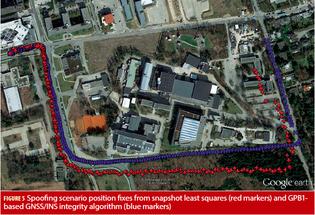
The previously introduced technique is demonstrated with a scenario employing a spoofer using a hardware constellation simulator. The scenario simulates a short drive of a land vehicle. The multipath environment was generated according to the ITU-R P.681 channel model; nominal Galileo and GPS constellations were assumed. Additionally, an ideal spoofing of one Galileo and one GPS Open Service signal was simulated. From a certain point in time onwards, a ramp on the pseudoranges of the respective satellites was generated, starting from zero. Using this RFCS scenario, baseband samples were recorded and then post-processed with the PIPE Receiver. Additionally, artificial inertial sensor data simulating a medium-grade MEMS was generated.
The results of the post processing of the recorded baseband samples are shown in Figure 5. The trajectory starts in the left upper corner and follows the road that is visible in the Google Earth picture. Two different PVT solvers were used: a snapshot least squares solver that produced the position fixes indicated by the red markers, and the GNSS/INS filter bank approach described in the previous section, indicated by the blue markers. Obviously, the snapshot least squares position fixes, for which no attempt to counter spoofing was made, walks off the road. In comparison, the GPB1-based GNSS/INS integrity algorithm proves to be robust with respect to the simulated spoofing threat.
Conclusion
To further grow the application of GNSS receivers for landbased applications, the integrity of the computed PVT solutions must be ensured for this user community in a comparable fashion as is done for the aviation industry. In doing so, the integrity risks of the respective applications like vehicles in cities and railways have to be accounted for. The list of nominal and non-nominal threats is comprehensive, ranging from false locks during tracking over unintentional interference and intentional counterfeiting of GNSS signals, i.e., spoofing.
During the INLU project, various state-of-the-art and promising candidates of future receiver techniques are studied to understand how they can contribute to robust PVT results for land-based users. This comprises not only tracking and RAIM algorithms but also integration of GNSS with inertial measurements using, for example, filter banks.
A GNSS end-to-end simulator needs to have a high versatility to be able to accommodate the manifold requirements that such a project imposes on it. Key factors for the achieved flexibility of the PIPE and SNIPE tools are:
- partitioning into units that serve single tasks with clear inter-module and input data interfaces,
- abstraction layers that allow for the addition of tracking and PVT computation methods to the receiver with minimum effort and the ability to operate these in bit-true and semianalytic modes.
The effectiveness of the chosen approach was demonstrated in a scenario where a traditional GNSS receiver was misled by a spoofer while the implemented filter bank approach corrected for the error transparently.
A separate article will report on the entirety of INLU’s results, i.e., the conclusions drawn from results gained from a number of stochastic scenarios.


