 FIGURE 1: Characterization of interference from the user perspective
Increasing demand for ensuring the authenticity of satellite signals and position/velocity/time (PVT) calculations raises the need for tools capable of assessing and testing innovative solutions for verifying GNSS signals and PVT. Today’s civilian systems do not provide authentication at the system level, and a number of mitigation strategies have been developed in the last 10 years at user segment in order to protect receivers from interference and deception.
Increasing demand for ensuring the authenticity of satellite signals and position/velocity/time (PVT) calculations raises the need for tools capable of assessing and testing innovative solutions for verifying GNSS signals and PVT. Today’s civilian systems do not provide authentication at the system level, and a number of mitigation strategies have been developed in the last 10 years at user segment in order to protect receivers from interference and deception.
However, the lack of tools and instruments capable of evaluating these protection techniques prevents system integrators and end users from determining the solutions’ robustness and identifying associated risks. This situation is mainly due to the fact that existing tools are designed to simulate the performance and integrity of user equipment in non-intentional interference scenarios. Those tools that are used to assess intentional interference typically are limited to radio frequency interference (RFI) scenarios.
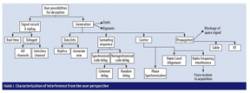
The core problem arises from the difficulty of characterizing all the different possibilities of position and time deception or “spoofing,” such as the simulation of signals together with interfering signals, replicating space data, or synchronizing of authentic and counterfeit signals. Figure 1 (see inset photo, above right) characterizes the avenues of attack for these spoofing attempts.
Another limitation of existing tools is that they do not allow the test and implementation of authentication schemes at the data and signal levels. Existing commercial products implement the signal-in-space (SIS) as defined by the respective interface control documents (ICDs) and find it difficult, for example, to simulate new schemes for data modulation, authentication, or multiplexed coding.
This article describes the high-level system architecture of the GNSS Authentication and User Protection System Simulator (GAUPSS) test bed, together with some preliminary results. The tool has been integrated in the European Space Agency (ESA) radionavigation lab at the European Space Research and Technology Center (ESTEC) in Noordwijk, The Netherlands, where GAUPSS is in its final validation phase.
The GAUPSS design had to meet four key types of requirements: the generation of deception scenarios, implementation of detection techniques based on satellite signal observables, generation of open GNSS signals that embed authentication, and detection of deception in the digital signal processing (DSP) domain. The sidebar, “GAUPSS Functional Requirements,” (at the end of this article) describes each of the categories of requirements in further details.
GAUPSS Architecture
The GAUPSS testbed architecture has been planned so as to allow a fully software implementation, leveraging the use of existing professional, commercial off the shelf (COTS) hardware equipment for both GNSS simulators and receivers. This allows maximum flexibility in the design and integration of mitigation strategies, interfaces, and evolution of the tool. Figure 2 presents a schematic outline of the GAUPSS architecture.
Of particular note among the various components that have been developed and integrated in GAUPSS are:
SCS (Simulator Controller Software). This unit receives data from space via a receiver interface and controls commercial GNSS simulators in order to generate all possible types of interference and deception that can assail a target receiver. This software reveals in a user-friendly interface the combination of the full capabilities of signal generators that are otherwise not directly available to a user (time tagged scenarios, time synchronization, smooth signal generation without committing hardware resources, calibration capabilities).
SVAM (Signal Validation and Analysis Module). The SVAM connects to the target receiver and monitors the effectiveness of the various deception and interference techniques. Furthermore, this unit is in charge of integrating the detection techniques based on observable data in a target receiver.
SASMO — Signal Authentication Sequence (SAS) and Navigation Message Authentication (NMA) Module. The SASMO is a fully multi-constellation GNSS software signal simulator capable of generating open GNSS signals and adding authentication schemes in both the data and spreading code domains. The unit can also interface to commercial GNSS simulators in order to import a simulation scenario.
SWR (Software Receiver). This is a multi-constellation GNSS receiver capable of acquiring and tracking GNSS signals and performing a position solution. It integrates authentication mechanisms generated by SASMO and detection of counterfeit signals at both the acquisition and tracking stages.
SCS and SVAM Use in Scenarios
The simulator controller software and signal validation and analysis module — referred to as SCSV when their operation is discussed together — can operate in various architectures in order to support static and dynamic scenarios, and can perform tests with both SIS and simulated open GNSS signals.
The first architecture of interest is one that attempts to counterfeit space signals and test possible mitigation strategies. Designed for laboratory use, this architecture requires an external antenna for reception of space signals and is limited to static scenarios. A second architecture was developed to test dynamic scenarios in a laboratory environment and requires the use of two GNSS simulators, which are controlled by the simulator controller software.
A third architecture has been designed to add the capability of testing dynamic scenarios with the support of the multipath function of GNSS simulators. With this approach, authentic signals are generated by the standard feature of the constellation simulator, while the multipath capability simulates the effects of a counterfeited signal. The architecture allows very accurate testing of code and frequency offsets.
SCSV Architecture 1. In Architecture 1, a receiver (RxB) receives signals-in-space from a reference antenna and extracts observable data, orbits information, and real-time navigation data. This data is used by the SCS to create simulations perfectly aligned with the live signals both in data and range.
Simulation time is disciplined by the RxB 1 pulse per second (1PPS) in order to generate coherent signals with one- to three-nanosecond accuracy. As shown in Figure 3, SIS and simulated signals are combined and fed to the target receiver (RxA). SCSV collects data from RxA in order to assess the receiver lock state, carrier-to-noise (C/N0) ratio, and range variations and compare them with the ones that are generated for the signal simulator by SCSV.
SCSV Architecture 2. Architecture 2 has been designed to test dynamic scenarios in a laboratory environment (Figure 4). It requires two GNSS signal generators: one signal generator acts as the space signal, while the second acts as an interferer.
RxB is still used to collect reference orbit and navigation data parameters, while RxA receives the combined signal from both RF signal generators. In this architecture the authentic GNSS signal generator controls the time sync of the second signal generator via a 1PPS interface.
SCSV Architecture 3. Figure 5 shows the third SCSV architecture, which uses a single GNSS signal generator to assess both static and dynamic scenarios. The GNSS constellation simulator generates authentic signals, while the multipath signals are controlled by an external software that generates the spoofed pseudoranges.
This allows, for example, the testing of scenarios where the dynamics are identical in a first phase, and in a second phase the counterfeited signal (simulated by multipath) attempts to cause the target receiver (RxA) to deviate to a desired dynamic. This mode allows fine testing of algorithms and the simulation of all possible scenarios of code and frequency offset for multiple channels. It also allows the evaluation of different authentic and counterfeit signal combinations.
When the SCS starts a simulation, it has the capability to control power and range on the counterfeit signals in order to attempt to deceive the receiver. For example, the tool can support a simulation that begins with all authentic signals, then attempts to switch on and raise the power of a fake PRN (pseudo-random noise code of a signal) perfectly aligned with the authentic one, increase the power in order to get the receiver to lock on the new signal, and modify the code range in an attempt to create a false final PVT solution.
Figure 6 is a screenshot of the SCS graphical user interface (GUI), which shows the C/N0 and pseudorange monitor on the left side. The central area of the GUI screen deals with channel controls, and the right side shows the correlation peak output of the receiver.
Real-time data is used particularly to assess the receiver behavior under a spoofing barrage and can provide awareness and results on the effects of different scenarios.
The SVAM module collects data from the target receiver (RxA) for the purpose of analysis and implementation of detection strategies. The module supports three types of investigation and detection mechanisms:
- detection based on analysis of observables data
- detection based on analysis of navigation data
- detection based on pseudorange measurement residual (based on RAIM).
The tool supports the setting of parameters for thresholds in observable data jumps (such as time, C/N0, pseudorange jumps, or total lock time). This can provide a primary indication of receiver deception, particularly when the sophistication of the interferer is low (where, for example, ranges and power are not synchronized).
Navigation data is also compared with SIS data in order to assess if the navigation data is authentic. The analysis of navigation data is of particular interest for monitoring which signal is tracking the receiver, as SCSV has the capability to modify the bits or to set specific flags in spare bits in order to monitor when the counterfeit signal has taken over. Figure 7 presents a screenshot of the SVAM GUI with the navigation data monitor.
Finally, detection based on RAIM has been implemented, in order to monitor out-of-range pseudorange measurement residuals that can be caused by such things as a single-channel transmitter (a pseudolite, for example).
SASMO Architecture
The SAS and NMA module is a multi-constellation GNSS software signal simulator designed to simulate authentication schemes. It generates open GNSS signals and stores the I/Q (in phase and quadrature) signal samples in a file to be processed by the GAUPSS software receiver.
The following blocks comprise the SASMO architecture (shown schematically in Figure 8):
- an interface to import GNSS simulator scenario data, including constellation propagation information (code delay, Doppler) and navigation data
- a simulation engine block that manages the data and signal generation based on the simulation scenario
- a data decoder/encoder block that adds the authentication data in the predetermined fields. The bits to be included in the authentication function and the signature bits are identified in signature masks so that the user can test different position in the data frames.
- the NMA generator block, which loads the crypto keys and generates signatures based on both symmetric and asymmetric protocols
- a signal generation block capable of generating GPS and Galileo signals on I/Q samples
- an SAS generator block that generates authentication schemes based on SAS (described in further detail in the paper by O. Pozzobon et alia listed in the Additional Resources section at the end of this article).
The signal generated by SASMO can be transmitted via RF software defined radio with a mixer upconverter. Figure 9 shows a screen display of a SASMO GPS signal.
NMA Schemes Implemented in SASMO. Navigation message authentication has been integrated into SASMO with two options:
- Fast authentication scheme refers to a symmetric key encryption protocol based on a keyed-hash message authentication code (HMAC). This method requires limited bits, which can be truncated. It could be applied, for example, in possible evolution of Galileo at every page (two seconds) in a navigation message.
- Slow authentication scheme refers to a public key authentication method based on the Elliptic Curve Digital Signature Algorithm (ECDSA). This type of scheme requires more bits and could be applied in possible evolution of Galileo at every subframe (30 seconds).
Symmetric schemes based on HMAC use limited bandwidth, but they require a security module in the receiver (otherwise the key could be re-used for HMAC generation).
Public-key schemes based on ECDSA require a simpler receiver architecture, but signature size is significantly larger. In ECDSA the signature cannot be truncated because the entire data set must be decrypted by the receiver for verification. Table 1 shows examples of key sizes that have been tested in SASMO, with the relevant difference in signature size. Definition of security parameters (such as key size or initialization vector structure) is not an objective of this paper.
Signal Authentication Sequences (SAS)
SAS is a concept proposed in the previously cited paper by O. Pozzobon et alia that refers to the advanced release of a short sequence of encrypted PRNs in a non-encrypted data channel in the same frequency.
In a hypothetical implementation of this concept, the satellite would transmit in the navigation data of a non-encrypted signal a small sequence of chips that are later used for modulation of the encrypted signal. The receiver then attempts to correlate the received SAS data with the encrypted signal at the predetermined epoch, and verifies the correlation value with respect to a predefined security threshold.
Figure 10 shows an example of how SAS is obtained from an encrypted sequence.
SASMO supports SAS generation. SAS data is obtained by encrypted channels (generated by dummy PRNs) and stored for subsequently transmission.
Software Receiver Architecture
The GAUPSS SWR is a software-defined multi-constellation GNSS receiver designed to support detection and mitigation of counterfeit signals by implementing the following strategies:
- support of NMA as generated by the SASMO simulator
- support of SAS as generated by the SASMO simulator
- detection of counterfeit signals at both acquisition and tracking stages using DSP techniques.
Figure 11 shows the SWR high level architecture, comprising the acquisition, tracking, and position blocks (gray) and the signal authentication blocks (brown).
The DSP techniques that have been designed include the search of secondary peaks during the acquisition phase and the definition of a number of “sentinel” correlators in the tracking phases for monitoring the presence of other signals. These techniques are further detailed in the next section.
NMA data is verified after bit extraction. SAS sequences are verified during the tracking phase at every second. Suspect PRNs detected from the DSP, NMA, and SAS blocks are reported to the position solution function for exclusion and alert notification.
SWR can track signals directly via SASMO, via file interface or can acquire signals from the hardware front-end interface. The software-defined radio mentioned earlier has been used for both signal transmission via SASMO and signal reception via the SWR. The SWR is used also to acquire signals generated by SCSV via GNSS signal generators, in order to test DSP techniques for detection of deception attempts.
Preliminary Results of Mitigation Techniques
Detection of counterfeit signals in the tracking loop domain has been enhanced in the software receiver in order to have a configurable number of tracking points that can detect non-authentic signals entering the tracking loop.
The standard approach that employs three (bi-phase shift keying, BPSK) or five (binary offset carrier, BOC) correlators cannot be used to distinguish any spurious component in the autocorrelation function (ACF), due to the limited number of samples taken from the whole ACF. Figure 12 shows a counterfeited signal entering the correlator and not being detected by standard tracking function. Note that a malicious signal that is synchronized in range with a real signal can appear as multipath. Differentiating between them is not trivial and is not an objective of the current work.
Our approach is based on the design of a correlation subsystem, referred to as the “Sentinel Engine,” that runs in parallel with the ordinary E/P/L (early/prompt/late) correlation function. The Sentinel Engine’s correlators can be defined with an unlimited number and different delays with respect to E/P/L, providing a finer resolution for searches in the time domain. (See Figure 13.)
This allows the development of metrics (algorithms) that can detect counterfeit signals that attempt a so-called “carry off attack,” where an attacker attempts to align a false signal with a real one in order to force the receiver to lock onto the first one. (The paper by T. E. Humphreys et alia listed in Additional Resources is another example of a testbed that can assess such attacks.)
When under attack, the counterfeit signal generates some distortion in the ACF, which is inconsistent with the ideal shape. Two metrics have been chosen to measure deviations and unbalancing of ACF distribution: Center of Mass (CoM) and Skewness (SKEW), following a similar approach derived from particle physics and mechanics.
Model Definition
In a real scenario, the RF signal is first filtered by the front-end, then down-converted to baseband, and finally multiplied and summed.
While the metrics should be evaluated from a statistical point of view, the derivation of expectation and variance becomes a complex mathematical problem due to the correlation properties of ACF: the defined metrics are non-linear combinations of correlated random variables, with non-negligible covariance terms that impede the resolution in closed form. As a consequence, the model has been simplified in order to accomplish a closed form evaluation.
For this reason, the metrics and models have been chosen in order to maintain the possibility of verification through closed formulas, minimize the effect of ACF model approximations, and maintain model variables as much as possible joined to the real-life parameters of the ACF.
Such constraints led to the adoption of a model of the shape of ACF: it has been “artificially” built in order to obtain a formulation for the mass Wi, as close as possible to the real ACF, but suitable to simplify calculations and get closed form formulas. Details of the mathematical model will be presented in future publications.
Metrics and ACF Model. CoM and SKEW will be used to evaluate the displacement (CoM) and unbalanc-ing (SKEW) of the distribution of ACF abscissas, with respect to the prompt position. Table 2 defines the terms used in this model.
Pre-Filtering. Sampling granularity, noise, and code cross-correlation strongly affect the performance of the chosen metrics. We have implemented a filtering method based on an analysis of the ideal ACF shape: noise filtering should take advantage of signal properties, provided that the counterfeit signal peak emerges from the noise floor.
As a result, the method makes use of a threshold to filter out the “low-mass” sentinels before calculation. The threshold is related to the noise floor properties (Figure 14). In other words, only “high-mass” sentinels must be used, in order to obtain a low-noise output.
Different simulations have been performed with both the SCSV and SASMO software on two GNSS systems that broadcast respectively BPSK and BOC(1,1) signals. The simulated dynamics are the following:
- BPSK-PRN-1: counterfeit signal starts at 0.2 second, with a constant attenuation of 0 decibel.
- BOC-PRN-5: counterfeit signal starts at 0.3 second, with a constant attenuation of 0 decibel.
- Pseudorange offset of the two attacking component vary upon time, as shown in Figure 15.
In the Figures 16 and 17, CoM and SKEW have been calculated without filtering on BPSK-PRN-1 and on BOC-PRN-5. Both of them are under attack, but the noisy nature is quite evident, and poor information on malicious signals can be deduced.
The filtering approach transforms the statistic properties of the metrics, in particular their variance. As a result, we can easily isolate variations from the nominal conditions.
The graphs in Figure 17 show how SKEW and CoM vary significantly at, respectively, 0.2 and 0.3 seconds, when the counterfeit signal enters the sentinel engine. We are currently investigating statistical analysis in closed form and verification via Monte Carlo simulation for the tuning of the proper thresholds. This will allow the minimization of false positives and false negatives.
Conclusion
The GAUPSS testbed is a baseline for performing analysis and research of user segment protection and signal authentication. The development of algorithms in the position solution domain and at the DSP level in the receiver are fundamental until future navigation systems provide authentication at the system level.
Finally, GAUPSS is an ideal testbed to assess the performances of future authentication schemes at system level, as the software module can be easily modified to test new encryption schemes at the data or spreading code level. Mathematical models with threshold definitions for DSP-based detection will be subject of future publications.
Additional Resources
[1] Humphreys, T.E., and J. A. Bhatti, D. P. Shepard, and K. D. Wesson, “The Texas Spoofing Test Battery: Toward a Standard for Evaluating GPS Signal Authentication Techniques,” Proceedings of ION GNSS 2012, Nashville, Tennessee, USA, 2012
[2] Scott, L., “Spoofs, Proofs & Jamming, Towards a Sound National Policy for Civil Location and Time Assurance” Inside GNSS, September/October 2012.
[3] Pozzobon, O., and L. Canzian, A. Dalla Chiara, and M. Danieletto, “Anti-spoofing and Open GNSS Signal Authentication with Signal Authentication Sequences,” in IEEE/NAVITEC 2010, Noordwijk, 2010
SIDEBAR: GAUPSS Functional Requirements
The main requirements for generating various deception scenarios include:
- capability of replicating signal-in-space navigation data
- capability of aligning space signals with replica signal
- single-channel range, phase, doppler, and power control
- multiple channels range, phase, doppler, and power control
- generation of RFI for stealth spoofing in order to force a receiver to switch from tracking to acquisition.
Detection techniques based on observables defined in the GAUPSS requirements include the capability to detect the following:
- inconsistencies in observable data, such as time, front-end gain, and pseudorange jumps
- navigation data inconsistencies with respect to the known authentic navigation data
- deception based on single-channel transmitters (e.g., pseudolites) based on receiver autonomous integrity monitoring (RAIM) techniques.
To fulfill the testbed’s main requirement to generate and verify GNSS signals that embed authentication, this includes the functional capability to add navigation message authentication (NMA) via cryptographic primitives, add signal authentication at the spreading code level, and to receive, decode, and verify the implemented authentication schemes.
Finally, the high-level requirements for DSP-based detection techniques are detection and exclusion of non-authentic signals in the receiver acquisition phase, and detection and exclusion of non-authentic signals in the receiver tracking phase.


