
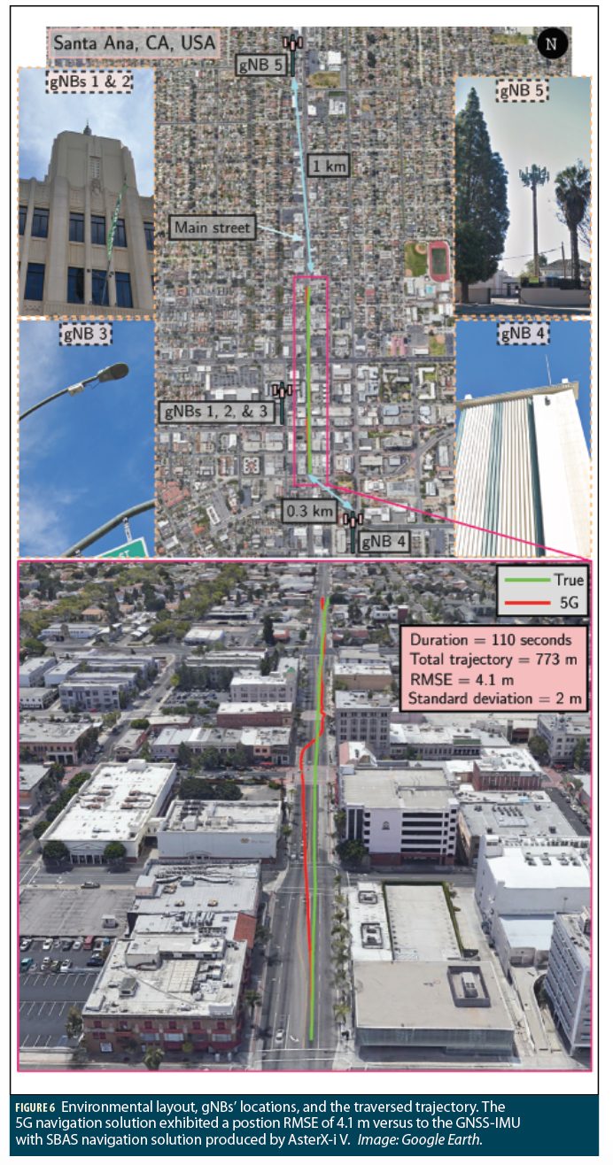
Innovative features of cellular fifth-generation (5G) signals enable the wireless system to play a major role in autonomous technologies. Test results of a ground vehicle navigating with signals from five 5G base stations (gNBs) over a trajectory of 773 m traversed in 110 seconds show a position root mean-squared error of 4.1 m.
ZAHER (ZAK) M. KASSAS, ALI A. ABDALLAH AND MOHAMAD ORABI, UNIVERSITY OF CALIFORNIA, IRVINE
Also known as new radio (NR), the next wireless communication system 5G provides faster data transfer speeds, lower latency, higher capacity, lower transmission power, and network slicing over fourth-generation (4G) long-term evolution (LTE). Autonomous vehicles involve enormous quantity of data collection, processing, and communication for navigation trajectory, traffic information, and surrounding vehicles and obstacles. 5G could revolutionize autonomous vehicles’ capabilities, from data sharing to navigation and situational awareness. This article assesses the potential of 5G signals for opportunistic navigation.
A carrier-aided code-based software-defined receiver (SDR) in this research produces navigation observables from received downlink 5G signals. These observables are analyzed to assess the performance of 5G signals for opportunistic navigation.
A wealth of recent research has considered the use of signals of opportunity (SOPs) as complementary and alternative navigation sources in GNSS-challenged environments [1]. SOPs are signals not intended for navigation purposes; however, they can be exploited for navigation, such as Wi-Fi [2], AM/FM [3], digital television [4], low-Earth orbit [5], and cellular [6[. Cellular signals, code-division multiple access (CDMA) and LTE, have shown high ranging and localization accuracy using specialized software-defined receivers (SDRs). See Reference [7]. To date, all 5G navigation results published in the literature have been limited to theoretical analyses, simulations, or laboratory-emulated 5G signals, due to:
• The structure of 5G signals has been recently finalized.
• 5G has been implemented only in a few major cities.
• The hardware for both reception and transmission in 5G systems, in which millimeter waves (mmWaves) are used, is still in development.
• The proposed navigation approaches require a network-based approach, in which the user’s privacy is revealed for the network. This also limits the user equipment (UE) to a single serving cellular provider, which limits the number of gNBs in sight.
This article describes the first experimental demonstration of navigation with real cellular 5G signals, tackling the aforementioned challenges by:
• Studying opportunistic navigation of 5G signals and presenting potential signals to be exploited for navigation purposes.
• Presenting an SDR to extract navigation observables from 5G signals.
• Implementing a navigation framework using an extended Kalman filter (EKF) to estimate the receiver’s position, along with the clock biases of the receiver and gNBs from extracted 5G navigation observables.
5G Signal Structure
Orthogonal frequency multiplexing (OFDM) with cyclic prefix (CP) is used as a modulation technique for 5G downlink signals, which is the same waveform LTE has adopted for its downlink signal. Here, we implement an opportunistic UE-based navigation approach; thus, only 5G downlink signal structure is discussed. OFDM uses a multi-carrier transmission scheme: transmitted data symbols are mapped into multiple narrowband subcarriers in the frequency-domain, which reduces frequency selective fading effect caused by multipath. The serial data symbol {S1,…,SN} are parallelized in group symbols, each of length NR, where NR is the number of subcarriers carrying the data. Then, a guard band in the frequency-domain is applied by zero-padding both sides of the signal and extending the NR subcarriers into Nc subcarriers. At this step, an inverse fast Fourier transform (IFFT) is taken, and the last LCP elements are repeated in the beginning, which serves as a guard band in the time-domain to protect the OFDM signals from inter-symbol interference (ISI).
At the receiver, the transmitted symbols are demodulated by executing these steps in reverse order. The obtained OFDM signals are arranged in a 2-D frame. The structure of this frame depends on the transmission type of the 5G signal, which can be either time division duplexing (TDD) or frequency division duplexing (FDD). Here, we use 5G signals from frequency range 1 (FR1), where most cellular providers are using FDD due to its providing better coverage and less latency.
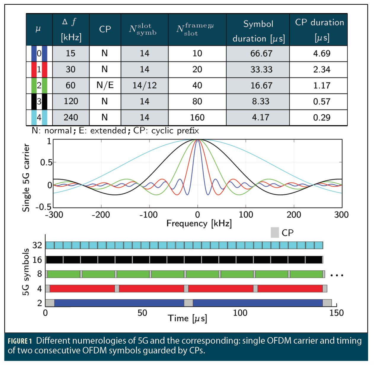
Compared to LTE numerology (i.e., subcarrier spacing (SCS) and symbol length), which supports only one type of subcarrier spacing, Δƒ=15kHz, 5G supports different types of subcarrier spacing. Figure 1 shows the different types, where μ denotes the numerology.
The duration of the FDD 5G frame is

where Δƒmax=480 kHz, Nƒ=4096, and Tc= =0.509 ns is the basic time unit for 5G. Each 5G frame consists of ten subframes, with duration 1 ms each. The number of OFDM symbols per subframe is
  =
= . The frame is divided into two equally-sized half-frames consisting of five subframes each and denoted by: (i) half-frame 0 consisting of subframes 0-4 and (ii) half-frame 1 consisting of subframes 5-9.
For a predefined μ, the number of slots is denoted by  or
or  in an increasing order within a subframe or a frame, respectively. The number of symbols per slot
  depends on the type of cyclic prefix and the specified numerology.
The table in Figure 1 shows for different numerologies: the number of OFDM symbols per slot, number of slots per frame, number of slots per subframe, and CP type.
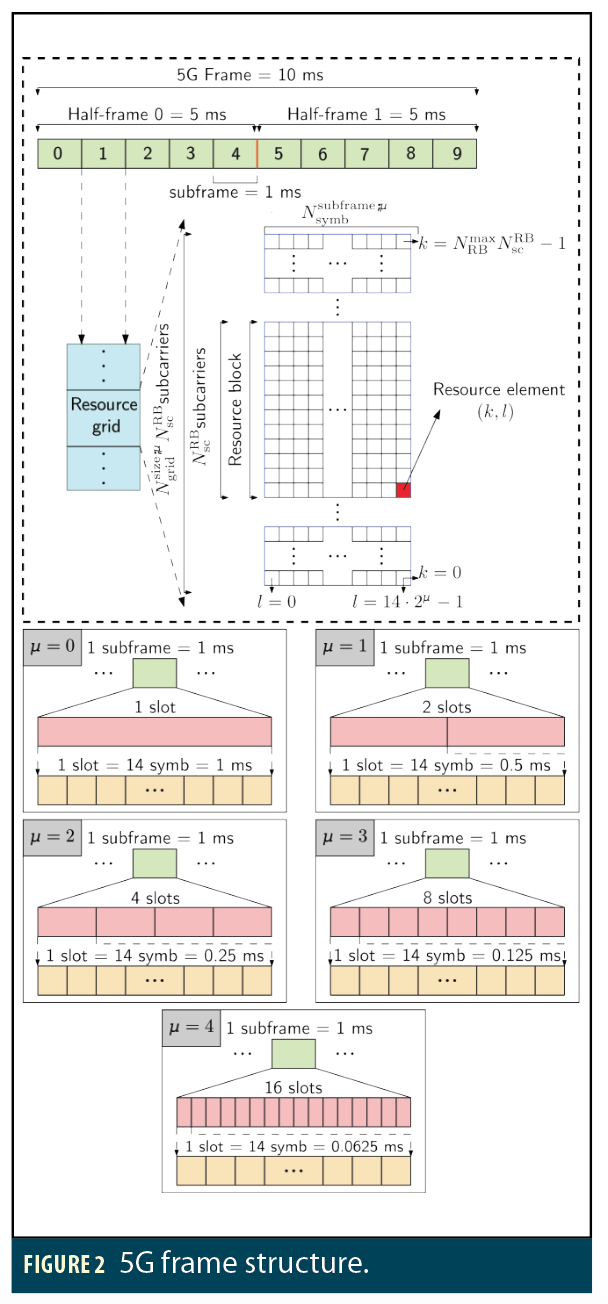
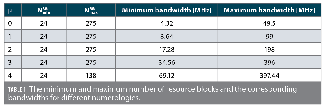
A resource block (RB) is defined as NscRB=12 subcarriers in the frequency-domain and has the time length of a resource grid . A resource block consists of resource elements. The minimum and maximum number of resource blocks along with the corresponding bandwidth for different numerologies are summarized in Table 1. Each element in the 5G frame is uniquely identified for a specific antenna port p and subcarrier configuration μ by (k,l)p,μ, where k is the index in frequency domain and l is the symbol position in the time domain relative to some reference point. In the 5G protocol, “Point A” serves as a common reference point. Figure 2 summarizes the 5G frame structure.
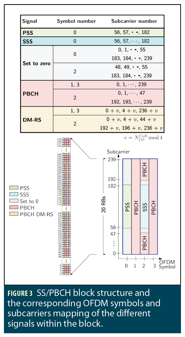
At the receiver side, the received 5G signal must be converted to frame structure before extracting signals of interest. To do so, the frame start time should be known. For the purpose of providing the frame start time, the gNB broadcasts synchronization signals (SS) with a pre-specified symbol mapping in the 5G frame. The SS includes two reference signals: primary synchronization signal (PSS) and secondary synchronization signal (SSS), which provide symbol and frame timing, respectively. Once the frame start time is known, the CPs can be removed and a fast Fourier transform (FFT) is taken to construct the OFDM symbols in the frame. The SS, the physical broadcast channel (PBCH), and its associated demodulation reference signal (DM-RS) are transmitted in the same 4 symbols block called the SS/PBCH block. The SS/PBCH block consists of 240 contiguous subcarrier (20 RBs) and four consecutive OFDM symbols. Within the SS/PBCH, the subcarriers are numbered in an ascending order from 0 to 239. Figure 3 shows the SS/PBCH block structure and the corresponding OFDM symbols and subcarriers mapping of the different signals within the block. Note that the position of PBCH-DM-RS varies with v, and the value v changes depending on the physical cell ID. The SS/PBCH block is transmitted every two frames and is transmitted numerous times, where each set of these transmitted block is called an SS/PBCH burst. The SS/PBCH burst has to be confined within a half-frame window (5 ms). Each block in the SS/PBCH burst is beamformed in a different direction. The frequency location of the SS/PBCH within the 5G frame depends on the 5G high-level signaling. The time location of the SS/PBCH block and the size of the SS/PBCH burst in the frame depends on the transmission frequency fc and the numerology μ.
The PSS and SSS are two orthogonal maximum-length sequences (m-sequences) of length 127 and are transmitted on contiguous subcarriers. The PSS has three possible sequences NID(2) ∈{0,1,2}, each of which maps to an integer representing the sector ID of the gNB. The SSS has 336 possible sequences NID(1) ∈{0,1,…,335}, each of which maps to an integer representing the group identifier of the gNB. Both NID(1) and NID(2) define the physical cell identity of the gNB according to

PBCH is a physical channel that is used to transmit the system information required to establish the connection between the gNB and the UE. The DM-RS signal associated with the PBCH is used for decoding purposes and estimate the channel frequency response.
5G Receiver and Navigation Framework
A carrier-aided SDR is used to opportunistically extract TOA measurements from 5G signals. The receiver has three main stages: 5G carrier frequency extraction, acquisition, and tracking.
Assuming the knowledge of the gNBs’ locations, the estimated TOA measurements are fed to an EKF to estimate the state vector defined as  where xr is the 3-D position and velocity of the receiver and xclk is the relative clock bias and drift between the receiver and each of the gNBs. The receiver dynamics are assumed to evolve according to nearly constant velocity dynamics, while the clock error dynamics are assumed to evolve according to the standard double integrator model driven by noise.
Experimental Demonstration
To the best of the authors’ knowledge, this demonstration of 5G opportunistic navigation for a ground vehicle navigating in a challenging urban environment is the first navigation solution produced using ambient 5G signals from serving gNBs.
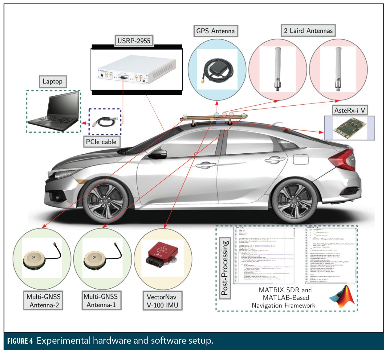
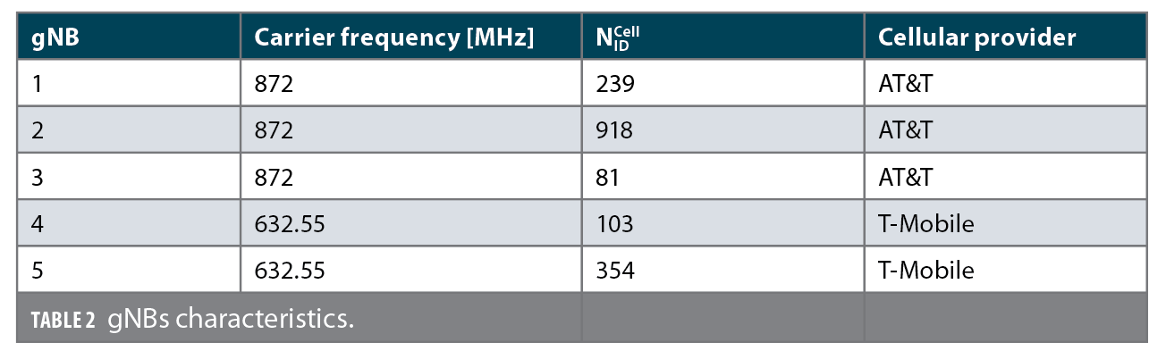
Experimental Setup and Layout. The experiment was performed on Main Street, Santa Ana, California. A quad-channel National Instrument (NI) universal software radio peripheral (USRP)-2955 was mounted on a vehicle; only two channels were used to sample 5G signals with a sampling ratio of 10 MSps. The receiver was equipped with two consumer-grade cellular omnidirectional Laird antennas. The USRP was tuned to two carrier frequencies corresponding to two U.S. cellular providers summarized in Table 2. The USRP was driven by a GPS-disciplined oscillator (GPSDO) and the sampled data were stored for post-processing. The vehicle was equipped with a Septentrio AsteRx-i V integrated GNSS-IMU whose x-axis pointed toward the front of the vehicle, y-axis pointed to the right side of the vehicle, and z-axis pointed upward. AsteRx-i V is equipped with a dual-antenna multi-frequency GNSS receiver and a VectorNav VN-100 MEMS IMU. The GNSS-IMU with SBAS navigation solution produced by AsteRx-i V was used as the ground truth in this experiment. Figure 4 shows the experimental hardware and software setup.
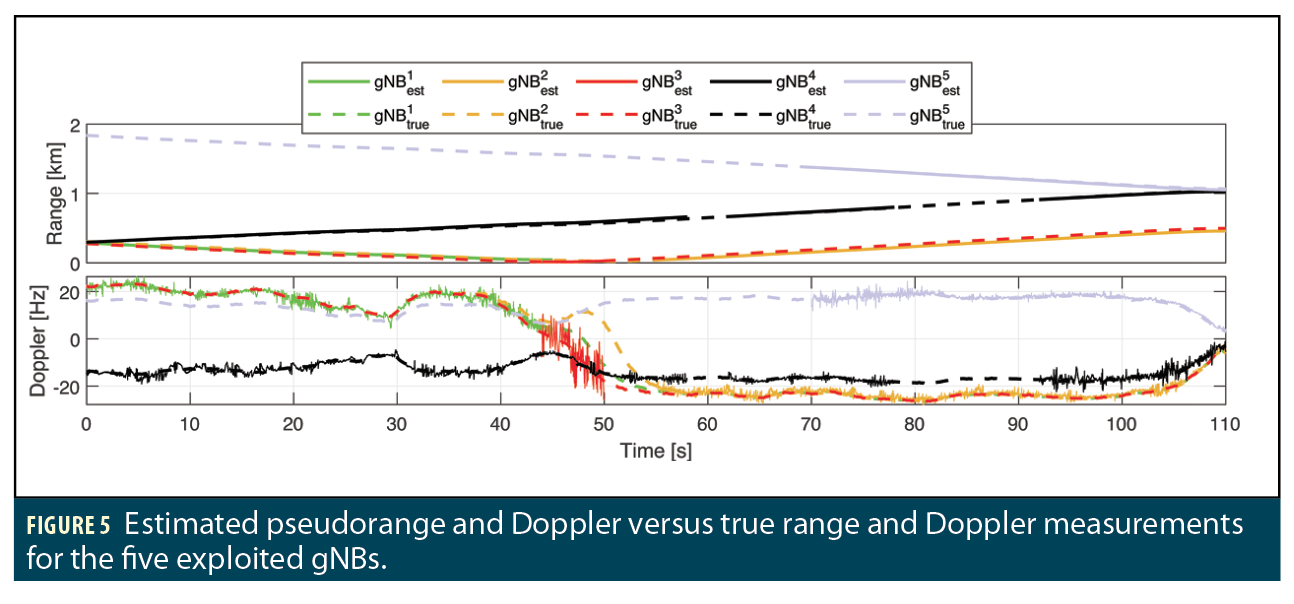
Navigation Solution. The vehicle traversed a distance of 773 m in 110 seconds. Figure 5 shows the true pseudorange and Doppler to all 5G gNBs versus the estimated pseudorange and Doppler as produced by ASPIN Laboratory’s Multichannel Adaptive TRansceiver Information eXtractor (MATRIX) SDR. The true range and Doppler measurements were obtained using the vehicle’s ground truth trajectory and the surveyed locations of the gNBs.
The EKF’s position and velocity state vectors and their corresponding covariances were initialized using the output of the GNSS-IMU system. The initial relative clock biases were eliminated, i.e., the EKF’s relative clock biases were initialized to zero. The first two 5G measurements were dropped, as the first two position estimates from the GNSS-IMU system were used to initialize the relative clock drifts. Figure 6 shows the environmental layout, the location of the gNBs, the opportunistic 5G navigation solution, and the vehicle’s ground truth trajectory.
Acknowledgments
The authors thank Joe Khalife for help in data collection. This work was supported in part by the Office of Naval Research under Grant N00014-19-1-2511; in part under the financial assistance award 70NANB17H192 from U.S. Department of Commerce, National Institute of Standards and Technology; and in part by the U.S. Department of Transportation under University Transportation Center Program Grant 69A3552047138.
This article is drawn from a paper at ION GNSS+ 2020, (see www.ion.org/publications/browse.cfm) though it presents new results.
References
(1) Z. Kassas, J. Khalife, A. Abdallah, and C. Lee, “I am not afraid of the jammer: navigating with signals of opportunity in GPS-denied environments,” in Proc. of ION GNSS+ Conference, 2020, pp. 1566-1585.
(2) R. Faragher and R. Harle, “Towards an efficient, intelligent, opportunistic smartphone indoor positioning system,” NAVIGATION, (62)1, pp. 55–72, 2015.
(3) V. Moghtadaiee and A. Dempster, “Indoor location fingerprinting using FM radio signals,” IEEE Trans. on Broadcasting, (40)2, pp. 336–346, 2014.
(4) C. Yang, T. Nguyen, and E. Blasch, “Mobile positioning via fusion of mixed signals of opportunity,” IEEE Aerospace and Electronic Systems, (29)4, pp. 34–46, 2014.
(5) Z.Kassas, J. Khalife, M. Neinavaie, T. Mortlock, “Opportunity Comes Knocking,” Inside Unmanned Systems, pp. 30–35, June 2020.
(6) K. Shamaei and Z. Kassas, “LTE receiver design and multipath analysis for navigation in urban environments,” NAVIGATION, (65)4, pp. 655–675, 2018.
(7) A. Abdallah, K. Shamaei, and Z. Kassas, “Assessing real 5G signals for opportunistic navigation,” in Proc. of ION GNSS+ Conference, 2020, pp. 2548-2559.
Authors

Zaher (Zak) M. Kassas is an associate professor at the University of California, Irvine and Director of the Autonomous Systems Perception, Intelligence, and Navigation (ASPIN) Laboratory. He is also Director of the US DOT Center for Automated Vehicles Research with Multimodal AssurEd Navigation (CARMEN). He received a Ph.D. in electrical and computer engineering from the University of Texas at Austin. He is a recepient of the 2018 National Science Foundation (NSF) CAREER award, 2019 Office of Naval Research (ONR) Young Investigator Program award, 2018 IEEE Walter Fried award, 2018 ION Burka award, and 2019 ION Col. Thomas Thurlow award.

Ali A. Abdallah is a Ph.D. student in the Department of Electrical Engineering and Computer Science at the University of California, Irvine and a member of the ASPIN Laboratory.

Mohamad Orabi is a Ph.D. student in the Department of Electrical Engineering and Computer Science at University of California, Irvine and a member of the ASPIN Laboratory.


