
Signal structure and ephemeris and timing error correction. Finding alternative positioning, navigation and timing (PNT) technologies to GNSS is more pressing than ever.
ZAHER (ZAK) M. KASSAS, SHARBEL KOZHAYA, JOE SAROUFIM, THE OHIO STATE UNIVERSITY
In February 2020, President Trump issued an Executive Order on Strengthening National Resilience through Responsible Use of PNT Services [1]. Since then, GNSS jamming and spoofing attacks, affecting civilian and military operations, have intensified worldwide, from the Mediterranean Sea, to the Middle East, to the Black Sea, to the South China Sea, to the Baltic, to the Atlantic [2]. Jamming and spoofing have become the “bread-and-butter” of electronic warfare.
The proliferation of low Earth orbit (LEO) constellations has kicked off global research to study LEO for PNT [3-6]. LEO satellites are abundant, offer favorable dilution of precision measures, and provide much higher received signal power and informative Doppler observables than GNSS. LEO PNT can be classified into four categories: (1) launching PNT-dedicated LEO constellations, (2) augmenting GNSS with LEO constellations, (3) dual-purposing LEO satellites to offer PNT services, and (4) exploiting LEO signals from any constellation in an opportunistic fashion.
This article considers the latter approach, focusing on exploiting Starlink LEO downlink signals of opportunity for PNT. To do this, one must deal with the: (1) undisclosed nature of the satellites’ proprietary downlink signals, (2) poorly known satellites’ ephemerides, and (3) unresolved timing error. This article presents an end-to-end approach to deal with those challenges. The authors argue that despite Starlink not transmitting a dedicated PNT signal, nor sharing precise ephemerides in the downlink, nor disclosing their timing and synchronization errors, one could, with carefully crafted algorithms, exploit Starlink’s communication signals to achieve nearly GPS-like PNT performance.
To this end, the article first presents a comprehensive characterization of Starlink’s downlink signal structure and a Starlink LEO PNT software-defined receiver (SDR) architecture that yields Doppler and pseudorange observables. Next, the article describes an approach to correct LEO ephemerides and timing error via a reference receiver. This approach possesses two desirable attributes: (1) very low bandwidth: the ephemeris error for each satellite is sufficiently captured by two parameters, estimated by the reference receiver (base) and communicated asynchronously to the navigating receiver (rover) and (2) very long baseline: the reference receiver can be placed hundreds of kilometers away from the rover, leading to a sparse reference network that is sufficient to provide corrections across the United States.
Using the presented models and SDR, the article presents the most accurate Starlink PNT results to date in published literature. The results show: (1) a stationary receiver localizing itself with Starlink signals to within 2 m in 20 seconds and (2) a ground vehicle navigating for nearly 3 km in Pittsburgh to meter-level accuracy by aiding its onboard inertial measurement unit (IMU) with Starlink Doppler observables while receiving corrections from a reference receiver in Columbus, 254 km away. The latter experiment is the first of its kind, showcasing a ground vehicle navigating exclusively with Starlink satellites.
Starlink Constellation Overview
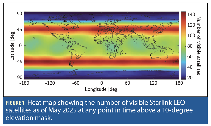
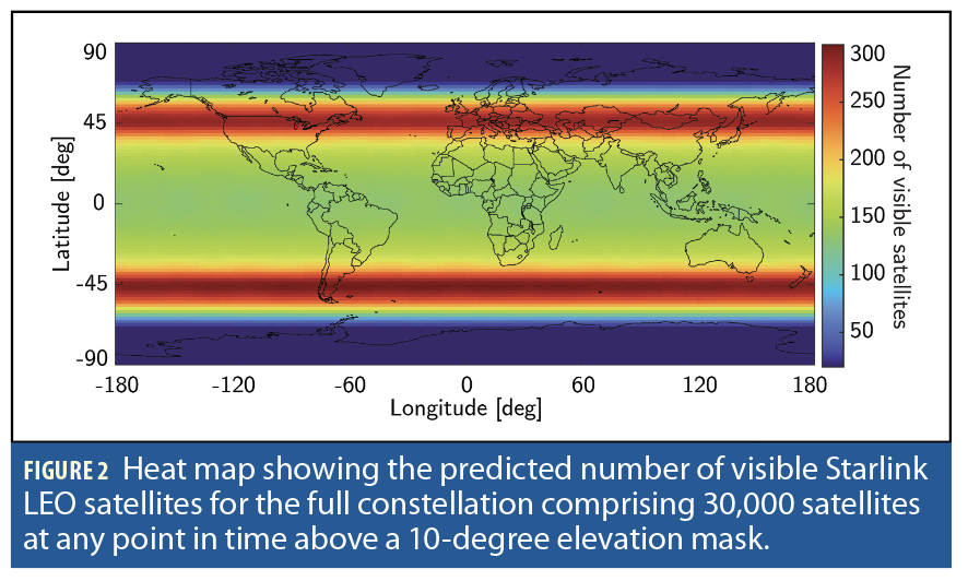
With more than 7,000 satellites already orbiting the Earth, SpaceX’s Starlink has more satellites in LEO than all other constellations combined. The Starlink constellation resides at an altitude between 540 and 570 km and comprises different satellite walker-delta shells with near-polar orbits. Figures 1 and 2
show a heat map of the number of visible Starlink LEO satellites at any point in time above a 10-degree elevation mask as of May 2025 and after the deployment of the full constellation comprising 30,000 satellites, respectively. These figures imply that more than 100 satellites are present above any non-polar region at any point in time. While these figures show the total number of Starlink satellites, a subset of these satellites is simultaneously active, transmitting data to subscribers.
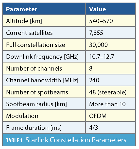
The Starlink constellation uses the Ku-band to transmit its circularly polarized downlink signals to user equipment. The Ku-band, spanning 10.7 to 12.7 GHz, is divided into eight 250 MHz channels. The Starlink constellation realizes a hexagonal cell deployment with 48 simultaneous steerable spot-beams with a radius of at least 10 km [7]. While the spotbeam of Starlink satellites is narrow, multiple satellites can simultaneously illuminate a given cell via different multiple-access techniques.
The multiple-access techniques employed by the Starlink constellation are: (i) time-domain: a subset of satellites transmit while the other is silent, (ii) frequency-domain: each satellite transmits at one of the eight different Ku-band downlink channels, (iii) polarization: the satellite uses right- or left-hand circular polarization, and (iv) power-domain: different power levels are allocated for different users. Table 1
summarizes some salient parameters of the Starlink constellation.
Starlink for PNT
While SpaceX is reshaping the communication sector with its commercial Starlink and military Starshield LEO, SpaceX has been eerily silent for the past few years about offering PNT services. Nevertheless, their intention to offer such services was revealed in May 2025 in response to the FCC launching proceeding on GPS complements via a Notice of Inquiry (NOI) on “Promoting the Development of PNT Technologies and Solutions.”
Shortly after the launch of the first batch of Starlink satellites, various studies began to populate the literature, ranging from investigating different aspects of the constellation [8] to its opportunistic exploitation in applications other than its originally intended purpose [9]. The first breakthrough to demonstrate the exploitation of Starlink signals of opportunity for PNT was achieved by tracking the carrier phase of one of Starlink’s persistent signals (referred to as “beacon”) [10]. Follow up research explored tracking the Doppler shift, upon acquisition via matched subspace detection [11] or a fast Fourier transform (FFT) [12].
The beacon these papers considered was a trail of nine unmodulated, data-less, pilot tones existing at the center of each Ku-band user downlink channel. Afterward, the literature further examined the structure of the downlink signals transmitted by Starlink [13-15], identifying that Starlink employs orthogonal frequency-division multiplexing (OFDM) for data modulation and exposed many signal parameters, particularly the primary and secondary synchronization sequences (PSS and SSS) [14].
The most comprehensive characterization of Starlink’s downlink signals for PNT to date was unveiled in [16], in which (1) the full OFDM beacon was revealed, showing the published PSS and SSS only comprise 0.66% of Starlink’s full beacon; (2) theoretical and experimental description for exploiting Starlink for PNT was provided, showing the maximum achievable carrier-to-noise density ratio (C/N0) under different scenarios: (i) pilot tones versus OFDM-based beacons and (ii) low-gain versus high-gain reception captures; (3) a Starlink LEO PNT SDR was designed, yielding the first successful extraction of navigation observables (carrier phase, Doppler shift and code phase) from Starlink’s OFDM signals; (4) a detailed analysis of the quality of Starlink navigation observables, including (i) signal activity and power levels and (ii) timing corrections that contaminate extracted observables along with mitigation strategies.
The Full Starlink OFDM beacon
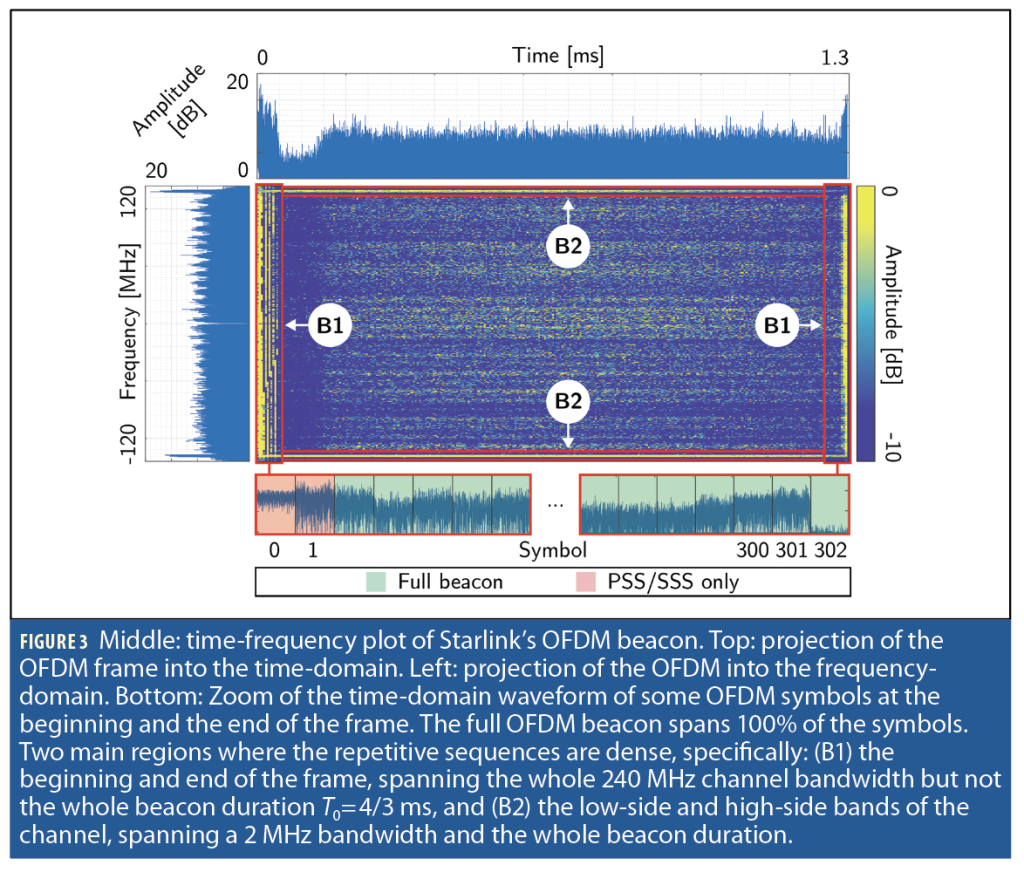
The blind beacon estimation framework, discussed in [17], was employed to estimate the beacon present in the Starlink Ku-band downlink OFDM signals. The frame of the final estimated Starlink’s OFDM beacon is shown in Figure 3 [16].
The Starlink beacon was found to span T0=4/3 ms. The bottom plots of Figure 2 show a zoom of some OFDM symbols at the beginning and end of the frame. While the percentage of symbols exploited in [14], [18] is 2/302=0.66% (PSS and SSS), the full OFDM beacon, exploited in this article, spans 100% of the symbols.
Exploiting the full Starlink OFDM beacon offers multiple advantages.
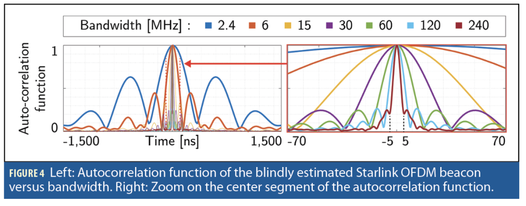
1. Large bandwidth implies improved resolution in the delay-domain, which manifests in narrower main lobe in the beacon’s autocorrelation function. Figure 4 shows the autocorrelation function of Starlink’s full OFDM beacon for receiver’s bandwidth ranging from 2.4 MHz to the full 240 MHz. Figure 4 implies that receivers exploiting the whole 240 MHz bandwidth and employing sensitive delay-locked loops (DLLs) are expected to achieve sub-nanosecond synchronization accuracy.
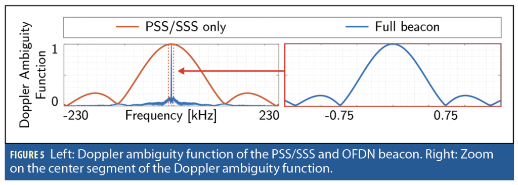
2. More symbols exploited (100%) implies longer integration time in the interval [0, T0], leading to an improved resolution in the Doppler-domain and better carrier tracking performance. Figure 5 shows how using the full OFDM beacon (blue) results in an expected first null at 750 Hz, whereas using only the PSS/SSS symbols (orange) leads to an expected first null at 113 kHz.
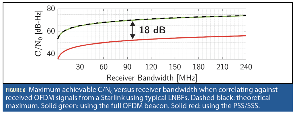
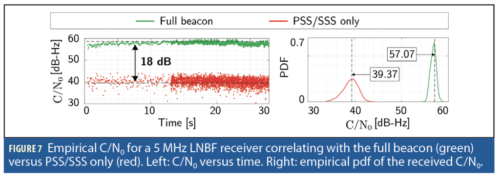
3. Exploiting additional resources, whether in time- or frequency-domain, increases the processing gain of the receiver and enables it to perform reliable acquisition and tracking under low signal-to-noise ratio (SNR) regimes, such as the one imposed by using low-noise block downconverter with feedhorn (LNBF). Using LNBFs ensures quasi-omnidirective reception in the Ku-band. Figure 6 shows (i) in dashed black the maximum achievable C/N0 using LNBFs as a function of the receiver’s bandwidth, (ii) in solid green the expected received C/N0 for a receiver correlating with the full OFDM beacon, and (iii) in solid red the C/N0 for a receiver correlating with the PSS/SSS only. Note that using the full OFDM yields an 18-dB boost in processing gain. Figure 7 shows an example of a tracked Starlink satellite using the PSS/SSS only versus the full beacon. The left plot shows the estimated C/N0 for a 5 MHz LNBF receiver correlating with the full beacon in green versus the PSS/SSS only in red. The right plot shows the empirical probability density function (pdf) of the received C/N0 for both beacons, which closely matches the theoretically predicted values discussed earlier.
Starlink PNT SDR Design
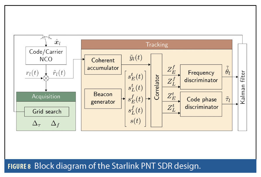
The Starlink SDR, similar to traditional GNSS receivers, operates in two stages: acquisition and tracking. In the acquisition stage, the SDR uses the full OFDM beacon (Figure 3) and cross-correlates it with the incoming signal. Over each T0, the SDR searches over a predefined set of delays and Doppler frequencies and checks if the Starlink beacon exists in the incoming signal. Typical Doppler search range for Ku-band LEO satellites is between -300 kHz and 300 kHz. When a Starlink signal is acquired, the SDR proceeds into tracking.
In the tracking stage, the SDR uses traditional DLL with non-coherent normalized early-minus-late envelope delay error discriminators. In addition to the DLL, the SDR employs a frequency-locked loop (FLL) with non-coherent normalized high-minus-low envelope frequency error discriminators. The errors from the discriminators are fed as innovation to a Kalman filter to keep track of the code phase and Doppler shift of the incoming signals from the tracked Starlink satellites. Figure 8 shows a block diagram of the Starlink PNT SDR.
Acquiring and Tracking Starlink Satellites
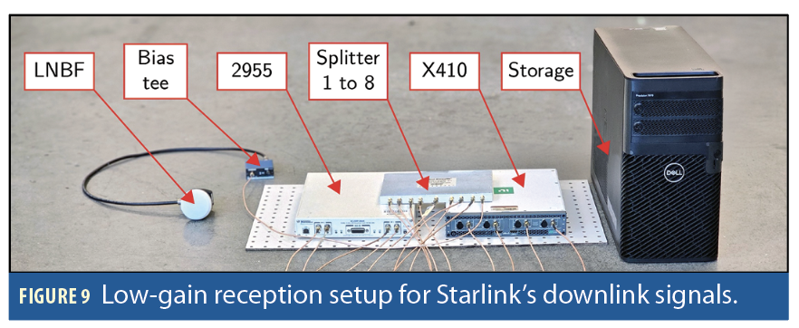
An upward-pointing LNBF was used to listen to overhead Starlink satellites. The recording took place at the ElectroScience Laboratory (ESL) at The Ohio State University in July 2024. The signal was recorded for 10 minutes with a Universal Software Radio Peripheral (USRP) 2955 and X410 and the data was stored for offline processing. The two USRPs were synchronized both in time and phase. The receiver was tuned to the center frequencies of the eight Ku-band downlink channels with a sampling bandwidth of 2.5 MHz. The block diagram of the low-gain capture is shown in Figure 9.
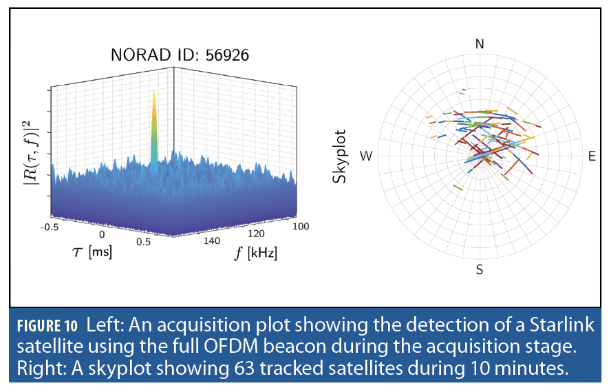
Similar to traditional GPS acquisition, the receiver was able to perform delay (τ)-Doppler (f) acquisition of overhead satellites by correlating against the full Starlink OFDM beacon. The left plot of Figure 10 shows the acquisition of a Starlink satellite, and the right plot shows a skyplot of the 63 tracked Starlink satellites.
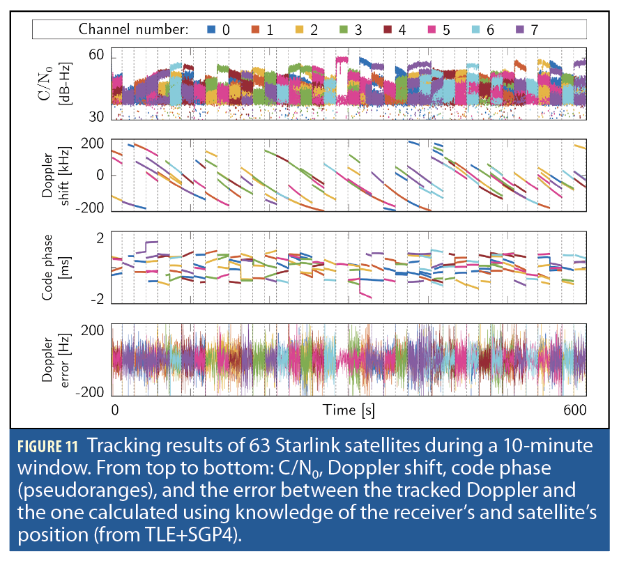
After acquisition, the Starlink satellites were tracked using the OFDM beacon. Figure 11 shows the estimated C/N0, Doppler shift, pseudorange, and Doppler error curves of the tracked satellites. The Doppler error was calculated by taking the difference between the tracked Doppler and the one predicted using knowledge of the receiver’s position and satellites’ positions from two-line element (TLE) files, propagated with simplified general perturbations 4 (SGP4) orbit propagation. Note how every 15 seconds, the satellite hops to a different channel frequency, the C/N0 (power-level) takes different cluster values, and the pseudorange exhibits an inexplicable overhaul of its dynamics, rendering standalone pseudorange-based PNT with Starlink unachievable without additional processing.
By listening to all eight Ku-band downlink channels with an upward-facing LNBF, the average number of simultaneously active Starlink satellites overhead was three. Note the number of active Starlink satellites overhead depends on surrounding user activity, location and time at which the receiver is listening to these satellites, making opportunistic Starlink PNT somewhat unpredictable. Nonetheless, the average number of active Starlink satellites is expected to increase as the number of subscribers grows and the constellation is fully deployed.
Positioning with Starlink Satellites
To demonstrate the achievable positioning accuracy with Starlink’s OFDM signals, 200 Monte Carlo realizations were used to initialize a batch weighted nonlinear least-squares (BWNLS) estimator to localize the receiver using Doppler shift measurement from Starlink satellites. The realizations were drawn from a Gaussian distribution, centered at the receiver’s true position with a covariance of

effectively yielding an uncertainty spanning Ohio and reaching neighboring states.
The batch window size was varied between 0.1 and 20 seconds and swept throughout the duration of the 10-minute dataset with a step size of 0.1 seconds to generate a positioning solution using all available satellites in a given window. The satellite’s position was predicted using TLE+SGP4. The propagated satellites’ positions were corrected for temporal and orbital errors, in post-processing, according to the zero-baseline approach in [19], and then used to generate the position solution. Figures 12 and 13 summarize the positioning performance.

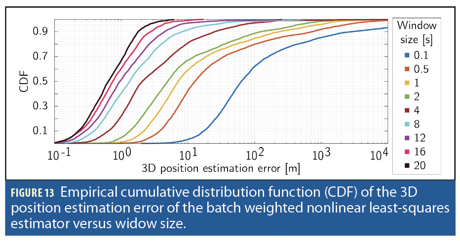
Figures 12 and 13 indicate that given an average number of three overhead Starlink satellites, a 90th percentile of 2 meters error is achievable in 20 seconds, and a 90th percentile of 10 meters error is achievable in 8 seconds. These are rather promising results, as they imply that if more precise ephemerides are available or the temporal and orbital errors can be corrected in real-time, nearly GPS-like PNT is achievable with Starlink, including supporting mobile applications with inertial aiding.
Reference Network Design for LEO Ephemeris Error Correction
Unlike GNSS, LEO satellites do not communicate ephemeris and clock error corrections in their downlink signals. Nevertheless, an estimate of their ephemerides can be obtained from publicly available TLE files and employing orbit propagation algorithms. However, the uncertainties in the TLEs yield accumulated errors in the propagated ephemeris, hindering their usability for PNT applications [20].
Several closed-loop tracking techniques have been introduced to tackle the ephemeris challenge by estimating satellite position and velocity [21], [22] or the argument of latitude, resolving the along-track error component [19], [23]. Furthermore, differential positioning has shown promising performance in reducing the effect of ephemeris errors between two receivers within a short baseline distance [24-27]. A recent study implemented a network-aided LEO PNT, showing promising positioning accuracy using communicated orbit and clock corrections [28].
An ephemeris error model was developed in [29],[30], enabling disambiguation of timing and LEO orbit errors from ranging measurements, leading to an approach to correct for LEO ephemeris errors by a reference receiver at very long baselines. This section builds on these results to design a sparse reference network for LEO ephemeris error corrections. First, a model of the LEO ephemeris error and its impact on the extracted range measurements is presented. The model is then employed to estimate the satellite’s position and timing error at a reference receiver, and subsequently correct contaminated measurements at another unknown receiver to improve its PNT accuracy. Finally, a sparse network of reference receivers covering the United States is designed.
Ephemeris Error Mapping into the Range Measurement Space
Consider a reference receiver R’ with prior knowledge of its exact position, capable of extracting pseudorange measurements from an overhead LEO satellite. The extracted pseudorange measurement z from the true LEO satellite to the receiver at time-step k is modeled as
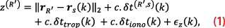
where with
and
being the clock biases of the receiver and LEO satellite, respectively; c represents the speed-of-light;
and
are the ionospheric and tropospheric delays from the LEO satellite to the receiver at time-step k, respectively; and
is the measurement noise, modeled as a discrete-time white Gaussian sequence with variance
(k). Standard ionospheric and tropospheric estimation models are assumed to be employed by the receiver; thereby
and
will be neglected in the forthcoming analysis.
Denote the erroneous estimate of the satellite’s position (e.g., obtained from TLE+SGP4) by . Let
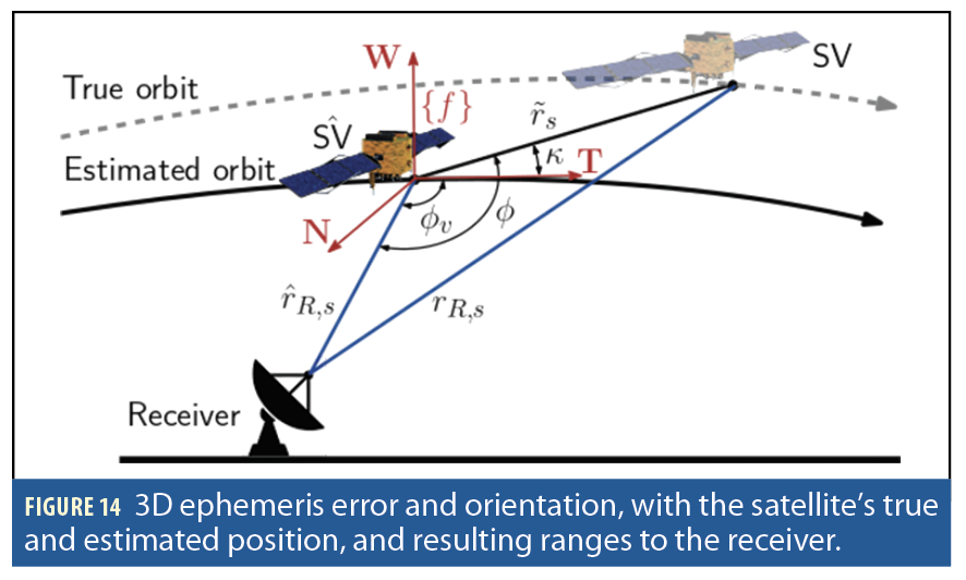
denote the satellite position estimation error. The erroneous ephemerides of each satellite map into a time-varying ranging error at the receiver given by
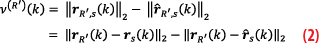
where

and

represent the true and estimated range vectors, respectively. Using the law of cosines (Figure 14),
the range error in (2) can be approximated as
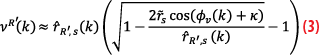
where is the angle between the estimated range vector
and the satellite velocity vector; and κ is the angle between the velocity vector and the satellite position error vector
. Note
κ characterizes the cross-track (W) and radial (N) error components with respect to the in-track (T) component in each satellite’s NTW frame. The model in (3) is a function of two unknown parameters: . and κ.
LEO Ephemeris Error Compensation
The pseudorange measurement in (1) can be written in terms of the predicted erroneous ephemeris by compensating for the ephemeris error using (3) as

where the clock terms are approximated to evolve as a first-order polynomial, with zero- and first-order terms and
being the relative clock drift. The resulting measurement model is now a function of four unknown static states: ephemeris error magnitude
, its direction angle from the velocity vector κ, and the clock terms a and b. The corresponding state vector
can be estimated via a BWNLS.
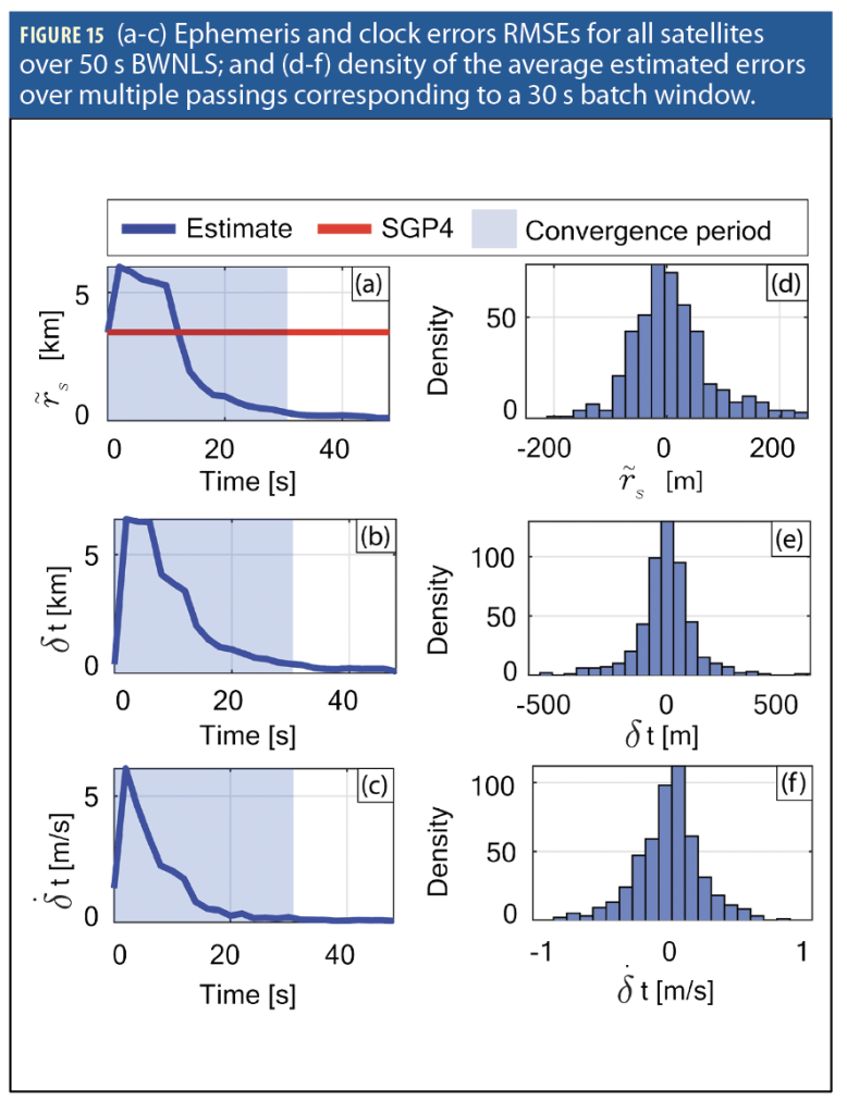
The performance of the BWNLS was assessed at a reference receiver simulated to extract pseudorange measurements from overhead LEO satellites, whose true and estimated ephemerides were generated by propagating TLE files via the high-precision orbit propagator (HPOP) and SGP4, respectively, over 8 hours. After 4 hours, the SGP4 ephemeris showed accumulated errors compared to HPOP, which will be assessed using the BWNLS estimator. The batch window size varied between 1 and 50 seconds with a step-size of 2 seconds to solve for the state vector using all visible satellites over a given window.
A total of 100 MC realizations were simulated for every window by randomizing the initial state estimates. Figure 15 (a-c) shows the root mean-squared errors (RMSEs) of the average MC runs for the ephemeris and clock error states (blue) and the RMSE of the SGP4 ephemerides (red) using 40 visible Starlink satellites. The ephemeris error RMSE dropped below 100 m at a window size of around 30 s, which will be referred to as the convergence time of the BWNLS. Figure 15 (d-f) shows the estimation error densities over 10 different 30 s windows, where the ephemeris error residuals had zero-mean and a standard deviation of 50 m, highlighting the accuracy of the estimator as compared to the SGP4 ephemerides [30].
To compensate for the ephemeris error contaminating extracted range-type measurements (pseudorange or carrier phase), the first two ephemeris states ( and κ) are sufficient. Therefore, these two parameters of each satellite can be communicated by the reference receiver to another receiver R, with unknown position, listening to the entirety or fraction of the LEO satellites. Receiver R employs the communicated parameters of each tracked satellite to correct for the time-varying ephemeris error impact on its extracted measurement via (3) [29].
Reference Network Design for Wide-Coverage LEO Ephemeris Error Correction
The aforementioned scheme can be used to design a reference network providing wide-coverage LEO ephemeris error correction over the United States. Consider a total of L reference stations capable of estimating the ephemeris parameters of all overhead LEO satellites (Figure 16). Each reference station communicates the most recent estimated parameters to a central database. This enables any unknown rover accessing the database to employ these parameters to correct its measurements to visible LEO satellites and accurately estimate its own states.
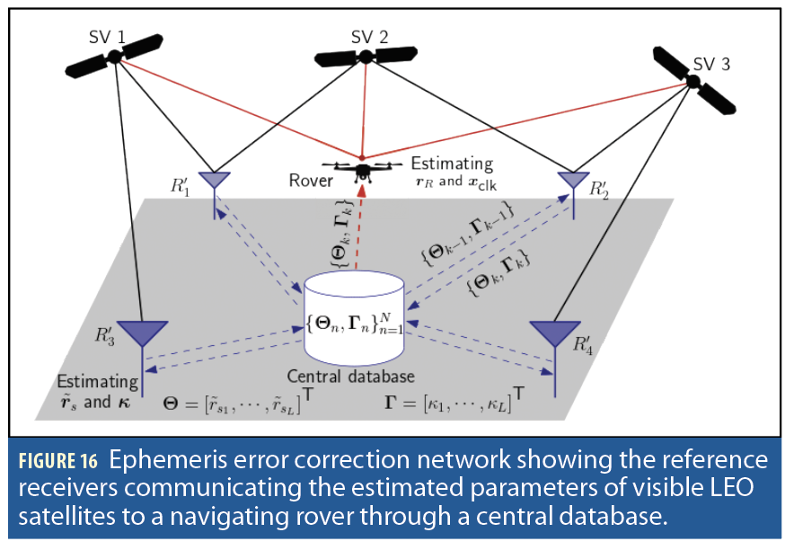
In contrast to traditional differential networks, the designed network possesses two unique and desirable attributes: (i) low communication bandwidth: the LEO ephemeris errors estimated by the reference receiver(s) are projected onto two parameters per satellite, which are sufficient to correct the rover’s ranging measurements; and (ii) sparsity: the very long baselines enable placing the reference receivers hundreds of kilometers away from the rover.
Simulation Study
This section evaluates the sparse reference network design for ephemeris error correction, enabling accurate LEO PNT with Starlink satellites over the United States.
Simulation Overview
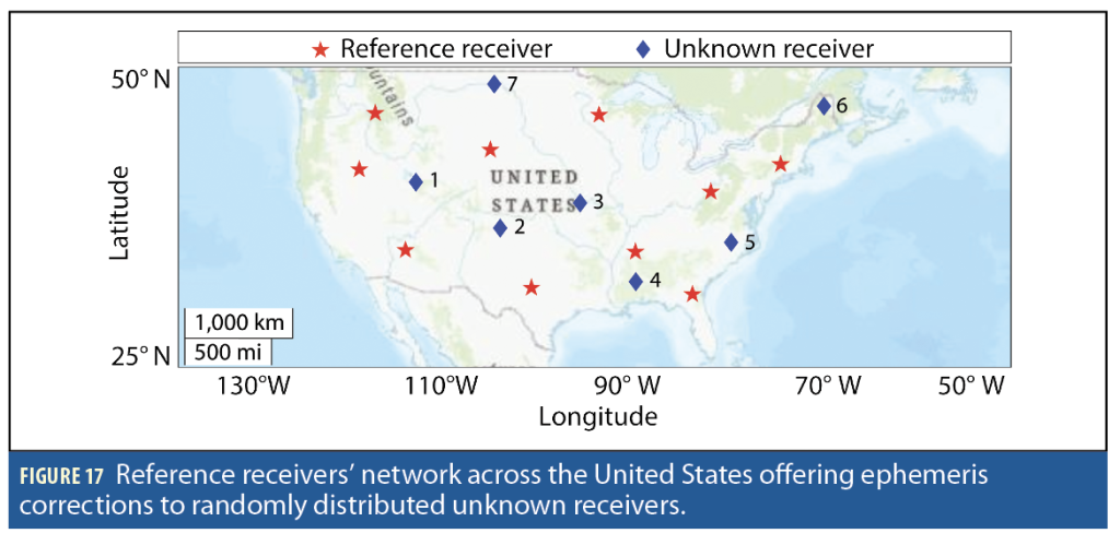
Ten reference stations were distributed across the United States, marked by red stars in Figure 17. The proposed ephemeris error correction scheme was implemented to localize seven stationary receivers with unknown positions, marked by blue diamonds in Figure 17.
The LEO satellites ground truth and estimated trajectories were generated by parsing and propagating 2,100 Starlink TLE data files over 12 hours via HPOP and SGP4, respectively. The ephemeris error compensation method was implemented after 4 hours of propagation. The receivers and LEO satellites were simulated to be equipped with oven-controlled crystal oscillators (OCXOs) and the clock bias and drift states were simulated to evolve according to the standard double integrator model driven by process noise [22].
Stationary Positioning
It is assumed the receivers with unknown positions have sole access to the central database and TLE data. At each receiver, extracted pseudorange measurements, along with the communicated ephemeris corrections of all visible LEO satellites, were fused in a BWNLS with a 20 s window size to estimate the receiver’s 3D position in the Earth-centered-Earth-fixed (ECEF) frame, as well as the zero- and first-order clock error terms.
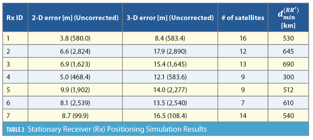
Positioning was performed through 1,000 MC realizations by randomizing the initial state estimates drawn from a Gaussian distribution, centered at the true receiver position and a covariance of . Table 2 summarizes the average horizontal 2D and 3D positioning results over all MC runs using uncorrected TLE+SGP4 versus the corrected ephemeris approach. The total number of satellites used and the distance to the nearest reference station are also summarized in Table 2. The 2D and 3D errors remained below 10 m and 18 m, respectively, which represent a significant reduction from TLE+SGP4 ephemerides whose error was hundreds to thousands of meters. The maximum number of satellites used by a particular receiver was 16, while the distance between the unknown receivers and the closest reference station ranged between 300 km and 690 km.
Experimental Results
This section presents experimental results validating the efficacy of the very long baseline ephemeris error correction approach. Two different experiments are presented: (i) stationary positioning via carrier phase measurements, with ephemeris parameters communicated over a 635 km baseline (St. Louis to Columbus); and (ii) LEO-aided IMU navigation via Doppler measurements, with ephemeris parameters communicated over a 254 km baseline (Columbus to Pittsburgh).
Stationary Positioning with Carrier Phase Measurements
The experiment was conducted in July 2024. The reference receiver was located in St. Louis, and the unknown receiver was on the ESL roof at The Ohio State University (OSU) in Columbus. The baseline distance between the two receivers was 635 km. During the course of 10 minutes, signals from 19 Starlink satellites were recorded over 1 Ku-band downlink channel in St. Louis using an upward LNBF and processed via a USRP B205 Mini. At the unknown receiver, signals from 37 Starlink satellites were recorded over all eight Ku-band downlink channels with an upward LNBF and processed via a USRP 2955 and X410. Only seven Starlink satellites were common between both receivers, and hence they were used to localize the unknown receiver.
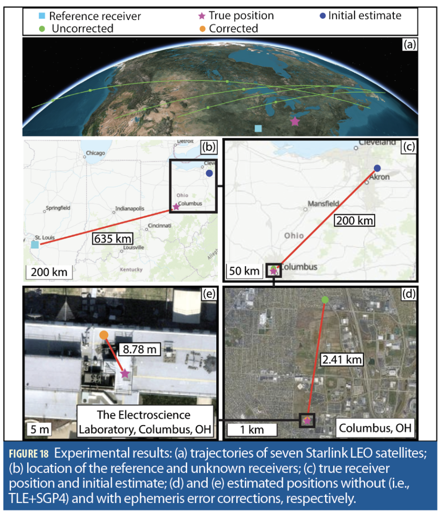
Ambiguous carrier phase measurements were obtained at both receivers after integrating the tracked Doppler shifts between the receivers and each satellite. The ephemeris parameters were estimated at the reference receiver using the method described in [29] and then fused at the unknown receiver into a BWNLS to correct the extracted carrier phase measurements. Figure 18 summarizes the positioning results showing: (a) the trajectories of the seven Starlink LEO satellites, (b) the location of the reference and unknown receivers; (c) true receiver position and initial estimate; (d) and (e) the estimated positions without and with ephemeris error corrections, respectively. Starting from an initial position error of 200 km, the corrected ephemeris approach reduced the 2D and 3D final position error from 2,410 m and 2,536 m to 8.78 m and 9.54 m, respectively.
LEO-aided IMU Navigation with Doppler Measurements
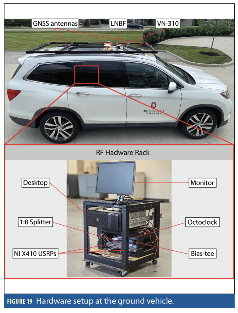
The experiment was conducted in June 2025. The reference receiver was located on the ESL roof at OSU. Starlink signals were recorded over all eight Ku-band channels using an upward LNBF, and sampled at 2.5 MHz via an NI 2955, an NI 2974, and an NI 2954 USRPs. The unknown receiver was a ground vehicle navigating without GNSS signals for 2.917 km in 118 seconds on Interstate 79 by Pittsburgh. The mean baseline distance between the two receivers was 254 km. The vehicle was equipped with a VectorNav VN-310 dual GNSS/INS operating with real-time kinematic (RTK) corrections and using a tactical-grade IMU, from which the vehicle’s ground truth was generated. Starlink signals were captured over all eight Ku-band downlink channels using an upward LNBF and processed at 2.5 MHz via two NI X410 USRPs. A description of the vehicle’s hardware is illustrated in Figure 19. Note the USRPs at both receivers were time-synchronized in post-processing.
During the experiment, signals from 15 Starlink satellites were captured at both receivers. With prograde orbits, most Starlink satellites orbit the Earth from west to east, hence flying over the reference receiver in Ohio before reaching the rover receiver in Pennsylvania. The reference receiver estimated four ephemeris parameters characterizing the effect of each satellite’s ephemeris errors on the extracted Doppler measurements: the satellite’s position error magnitude and its direction angle (similar to the ranging measurement case) as well as the velocity error magnitude and its direction angle. These parameters were then communicated to the ground vehicle to correct for the ephemeris errors in the TLE+SGP4 measurements. Starting with initial position and velocity estimates from the GNSS receiver, the ground vehicle navigated by fusing altimeter measurements in a loosely coupled fashion with its onboard IMU via an extended Kalman filter (EKF), while Doppler shift measurements from the 15 Starlink satellites were fused in a tightly coupled fashion to aid the IMU.
The IMU updates were performed at a rate of 200 Hz, altimeter updates were performed at 1Hz with measurement noise variance of 3 m2, while LEO updates were performed at 10 Hz with measurement variance inversely related to the received C/N0, ranging between 0.12 and 22.41 (m/s)2. The EKF state vector was
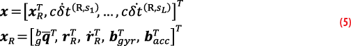
where is a 4D unit quaternion vector characterizing the orientation of the IMU body frame {b} with respect to the global frame {g}; rR and are the 3D position and velocity of the vehicle, respectively, expressed in {g}; bgyr and bacc are the 3D biases of the gyroscope and accelerometer, respectively, expressed in {b}, modeled to evolve according to velocity random walk dynamics; and L is the total number of satellites [22].
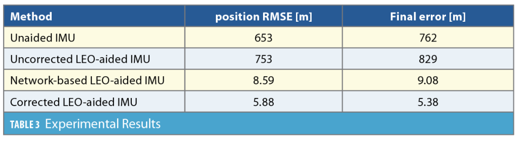
The experimental study compared four navigation strategies:
1. Unaided IMU: The vehicle navigates via open-loop dead-reckoning using inertial measurements.
2. Uncorrected LEO-aided IMU: The vehicle fuses uncorrected LEO measurements (TLE+SGP4) with IMU and altimeter measurements.
3. Network-based LEO-aided IMU: The vehicle fuses LEO measurements, along with communicated ephemeris corrections from the reference receiver in Ohio, with IMU and altimeter measurements.
4. Corrected LEO-aided IMU: The vehicle fuses LEO measurements, obtained from corrected ephemerides, with IMU and altimeter measurements. The ephemerides (from TLE+SGP4) were corrected with knowledge of the vehicle’s position, representing the case where more accurate Starlink ephemeris are made available.
Figure 20 shows the Starlink satellites’ trajectories, the two receivers’ locations, as well as the vehicle’s ground truth trajectory and estimated trajectories via the four navigation frameworks. Incorporating erroneous ephemeris from TLE+SGP4 drove the estimate to diverge from the ground truth, resulting in a position RMSE of 753 m, which is worse than the unaided IMU. Using ephemeris corrections communicated over a 254 km baseline achieved meter-level accuracy with a position RMSE of 8.59 m and a final error of 9.08 m. Using more accurate ephemerides further improved the navigation performance, achieving a position RMSE and final error of 5.88 m and 5.38 m, respectively. Note the latter approach still suffers from ephemeris errors (on the order of tens of meters). Having access to even more accurate ephemeris (e.g., meter level) is expected to improve the navigation performance even further. Table 3 summarizes the experimental results.
Conclusion
If and when Starlink will offer PNT services is yet to be seen. Regardless, this article showed Starlink’s communications signals can be a promising alternative PNT source, offering nearly GPS-like performance. While the achieved results revealed are promising, particular needs for military operations and civilian applications must be addressed if Starlink is to be used in practice for PNT. For instance, issues of integrity, availability and continuity remain largely unaddressed in the current opportunistic paradigm. What commitments should we require from Starlink and governing bodies? The authors hope this article will initiate a robust discussion by Starlink, standards bodies, government agencies, and PNT stakeholders into using (or dual purposing) Starlink as a complementary PNT solution.
Acknowledgment
The authors would like to thank Samer Hayek, Faezeh Mooseli and Paul El-Kouba for their help in experimental data collection and processing. This work was supported in part by the Office of Naval Research (ONR) under Grants N00014-22-1-2242 and N00014-22-1-2115, the Air Force Office of Scientific Research (AFOSR) under Grant FA9550-22-1-0476, the National Science Foundation (NSF) under Grant 2240512, the U.S. Department of Transportation under Grant 69A3552348327 for the CARMEN+ UTC, and the Aerospace Corporation under award 4400000428.
References
(1) United States, Executive Office of the President, “Executive order on strengthening national resilience through responsible use of positioning, navigation, and timing services,” February 2020.
(2) OPSGROUP, “GPS spoofing: Final report of the GPS spoofing workgroup,” September 2024, https://ops.group/blog/gps-spoofing-final-report.
(3) Z. Kassas, J. Morales, and J. Khalife, “New-age satellite-based navigation—STAN: simultaneous tracking and navigation with LEO satellite signals,” Inside GNSS Magazine, vol. 14, no. 4, pp. 56-65, 2019.
(4) Z. Kassas, M. Neinavaie, J. Khalife, N. Khairallah, S. Kozhaya, J. Haidar-Ahmad, and Z. Shadram, “Enter LEO on the GNSS stage: navigation with Starlink satellites,” Inside GNSS Magazine, vol. 16, no. 6, pp. 42-51, 2021.
(5) Z. Kassas, S. Kozhaya, J. Saroufim, H. Kanj, and S. Hayek, “A look at the stars: navigation with multi-constellation LEO satellite signals of opportunity,” Inside GNSS Magazine, vol. 18, no. 4, pp. 38-47, 2023.
(6) W. Stock, R. Schwarz, C. Hofmann, and A. Knopp, “Survey on opportunistic PNT with signals from LEO communication satellites,” IEEE Communications Surveys & Tutorials, vol. 27, no. 1, pp. 77–107, 2025.
(7) R. Blazquez-García, D. Cristallini, V. Seidel, J. Heckenbach, A. Slavov, and D. O’Hagan, “Experimental acquisition of Starlink satellite transmissions for passive radar applications,” in Proceedings of International Conference on Radar Systems, 2022, pp. 130–135.
(8) J. Garcia and S. Sundberg and G. Caso and A. Brunstrom, “Multi-timescale evaluation of Starlink throughput,” in Proceedings of ACM Workshop on LEO Networking and Communication, 2023, pp. 31-36.
(9) P. Gomez-del-Hoyo and P. Samczynski and F. Michalak, “Analysis of Starlink users’ downlink for passive radar applications: signal characteristics and ambiguity function performance,” in Proceedings of IEEE Radar Conference, 2023, pp. 1-6.
(10) J. Khalife, M. Neinavaie, and Z. Kassas, “The first carrier phase tracking and positioning results with Starlink LEO satellite signals,” IEEE Transactions on Aerospace and Electronic Systems, vol. 58, no. 2, pp. 1487–1491, 2021.
(11) M. Neinavaie, J. Khalife, and Z. Kassas, “Acquisition, Doppler tracking, and positioning with Starlink LEO satellites: First results,” IEEE Transactions on Aerospace and Electronic Systems, vol. 58, no. 3, pp. 2606–2610, 2021.
(12) N. Jardak and R. Adam, “Practical use of Starlink downlink tones for positioning,” Sensors, vol. 23, no. 6, p. 3234, 2023.
(13) Kozhaya and Z. Kassas, “Positioning with Starlink LEO satellites: A blind Doppler spectral approach,” in Proceedings of IEEE Vehicular Technology Conference, pp. 1–5, 2023.
(14) T. Humphreys, P. Iannucci, Z. Komodromos, and A. Graff, “Signal structure of the Starlink Ku-band downlink,” IEEE Transactions on Aerospace and Electronic Systems, vol. 59, no. 5, pp. 6016-6030, 2023.
(15) M. Neinavaie and Z. Kassas, “Unveiling Starlink LEO satellite OFDM-like signal structure enabling precise positioning,” IEEE Transactions on Aerospace and Electronic Systems, vol. 60, no. 2, pp. 2486–2489, 2024.
(16) S. Kozhaya, J. Saroufim, and Z. Kassas, “Unveiling Starlink for PNT,” NAVIGATION: Journal of the Institute of Navigation, vol. 72, no. 1, pp. 1-35, 2025.
(17) S. Kozhaya, H. Kanj, and Z. Kassas, “Multi-constellation blind beacon estimation, Doppler tracking, and opportunistic positioning with OneWeb, Starlink, Iridium NEXT, and Orbcomm LEO satellites,” in Proceedings of IEEE/ION Position, Location, and Navigation Symposium, 2023, pp. 1184–1195.
(18) E. Grayver, R. Nelson, E. McDonald, E. Sorensen, and S. Romano, “Position and navigation using Starlink,” in Proceedings of IEEE Aerospace Conference, March 2024, pp. 1–12.
(19) S. Hayek and Z. Kassas, “Modeling and compensation of timing and spatial ephemeris errors of non-cooperative LEO satellites with application to PNT,” IEEE Transactions on Aerospace and Electronic Systems, vol. 61, no. 3, pp. 5579-5593, 2025.
(20) Z. Kassas and J. Saroufim, “LEO PNT frameworks for non-cooperative satellites with poorly known ephemerides: open-loop SGP4, tracking, and differential,” IEEE Aerospace and Electronic Systems Magazine, pp. 1–18, 2025, early Access.
(21) N. Khairallah and Z. Kassas, “Ephemeris tracking and error propagation analysis of LEO satellites with application to opportunistic navigation,” IEEE Transactions on Aerospace and Electronic Systems, vol. 60, no. 2, pp. 1242–1259, 2024.
(22) Z. Kassas, N. Khairallah, and S. Kozhaya, “Ad astra: simultaneous tracking and navigation with megaconstellation LEO satellites,” IEEE Aerospace and Electronic Systems Magazine, vol. 39, no. 9, pp. 46-71, 2024.
(23) S. Hayek, J. Saroufim, and Z. Kassas, “Analysis and correction of LEO satellite propagation errors with application to navigation,” in Proceedings of ION GNSS+ Conference, 2025, pp. 1800-1811.
(24) J. Khalife and Z. Kassas, “Performance-driven design of carrier phase differential navigation frameworks with megaconstellation LEO satellites,” IEEE Transactions on Aerospace and Electronic Systems, vol. 59, no. 3, pp. 2947–2966, 2023.
(25) J. Saroufim, S. Hayek, and Z. Kassas, “Simultaneous LEO satellite tracking and differential LEO-aided imu navigation,” in Proceedings of IEEE/ION Position, Location, and Navigation Symposium, pp. 179–188, 2023.
(6) Y. Xie, G. Li, W. Zhou, M. Chen, and J. Yu, “Differential carrier phase positioning with system error corrections based on Orbcomm signals of opportunity,” IEEE Sensors Journal, vol. 25, no. 6, pp. 10063-10078, 2025.
(27) A. Hasan, H. Kabir, S. Islam, S. Han, and W. Shin, “A double-difference Doppler shift-based positioning framework with ephemeris error correction of LEO satellites,” IEEE Systems Journal, vol. 18, no. 4, pp. 2157-2168, 2024.
(28) Z. Komodromos, S. Morgan, Z. Clements, W. Qin, J. Morrison, and T. Humphreys, “Network-aided pseudorange-based LEO PNT from OneWeb,” in Proceedings of IEEE/ION Position, Location, and Navigation Symposium, pp. 439-449, 2025.
(29) J. Saroufim and Z. Kassas, “Ephemeris and timing error disambiguation enabling precise LEO PNT,” IEEE Transactions on Aerospace and Electronic Systems, vol. 61, no. 3, pp. 6138-6153, 2025.
(30) J. Saroufim and Z. Kassas, “LEO ephemeris error modeling enabling long baseline corrections for improved PNT,” in Proceedings of IEEE/ION Position Location and Navigation Symposium, pp. 625-630, 2025.
Authors
Zaher (Zak) M. Kassas is the TRC Endowed Chair in Intelligent Transportation Systems and a Full Professor at The Ohio State University. He is the Director of the Autonomous Systems Perception, Intelligence, and Navigation (ASPIN) Laboratory. He is also director of the U.S. Department of Transportation Center: CARMEN (Center for Automated Vehicle Research with Multimodal AssurEd Navigation), focusing on navigation resiliency and security of highly automated transportation systems. He received a B.E. in Electrical Engineering from the Lebanese American University, an M.S. in Electrical and Computer Engineering from The Ohio State University, and an M.S.E. in Aerospace Engineering and a Ph.D. in Electrical and Computer Engineering from The University of Texas at Austin. He received from President Biden the Presidential Early Career Award for Scientists and Engineers (PECASE), the highest honor bestowed by the U.S. government on outstanding scientists and engineers early in their careers. His awards include the National Science Foundation (NSF) CAREER award, Office of Naval Research (ONR) Young Investigator Program (YIP) award, Air Force Office of Scientific Research (AFOSR) YIP award, IEEE Richard Kershner Award, IEEE Harry Rowe Mimno Award, IEEE Walter Fried Award, Institute of Navigation (ION) Samuel Burka Award, and ION Col. Thomas Thurlow Award. He is a Fellow of the IEEE, a Fellow of ION, and a Distinguished Lecturer of the IEEE Aerospace and Electronic Systems Society and IEEE Intelligent Transportation Systems Society. His research interests include cyber-physical systems, navigation systems, cognitive sensing, and intelligent transportation systems.
Sharbel Kozhaya is a Ph.D. student at The Ohio State University and a member of the ASPIN Laboratory. He received a B.E. in Electrical Engineering from the Lebanese American University. He is a recipient of the Best in Track Paper Award (2025) and Best Student Paper Award (2023) at the IEEE/ION Position, Location, and Navigation Symposium (PLANS). His current research interests include opportunistic navigation, cognitive software-defined radio, and LEO.
Joe Saroufim is a Ph.D. student in the Department of Electrical Engineering and Computer Science at The Ohio State University and a member of the ASPIN Laboratory. He received a B.E. in Mechanical Engineering from LAU. He is a recipient of the Best in Track Paper Award (2025) at the IEEE/ION Position, Location, and Navigation Symposium (PLANS). His current research interests include situational awareness, autonomous vehicles, sensor fusion, and dynamic data driven systems.


