
A Global Navigation Satellite System (GNSS) aims to provide Earth-based position and navigation. Spaceborne GNSS receivers have become universal sensors for spacecraft navigation, especially in low Earth orbits (LEOs), often also supporting science endeavors or acting as dedicated science payloads.
SAHANA BANDAGADDE UMESHA, THOMAS KRAUS, NIKOLAS DÜTSCH, DR. CLOVIS MAIA, PROF. THOMAS PANY INSTITUTE OF SPACE TECHNOLOGY AND SPACE APPLICATIONS, UNIVERSITÄT DER BUNDESWEHR, MUNICH
This technology is crucial for many missions, especially in improving navigation systems. However, the rising threat of radio frequency (RF) jamming hinders LEO satellite missions that rely on precise positioning. Given this context, it is vital to consider the following questions: Are space receivers most at risk from jamming? How does jamming affect space receiver reliability? What mitigation techniques are available?
Recent advancements, noted as of late 2021, have expanded interception capabilities to include operations from the Earth’s surface, as detailed in [2]. These technologies also can disrupt LEO satellites’ RF communications by deploying mobile platforms. It’s clear jamming GNSS signals is emerging as a significant threat. A comprehensive analysis of space receiver jamming is presented in [3] and delves into techniques designed to enhance the robustness of receiver tracking loops, thus mitigating the adverse effects of jamming while maintaining precise positioning capabilities. Expanding upon [3], this article thoroughly examines jamming effects on a space receiver, focusing on factors like antenna pattern and link budget. It is closely tied to the ongoing development of Seamless Radio Networks for Internet of Space (SeRANIS) [4], a LEO satellite mission at the University of the Bundeswehr, Munich.

Small Satellite Missions and the Need for Jamming Mitigation
The SeRANIS satellite plays a pivotal role in various research domains, such as space communications that include broadband communications and Internet of things (IoT), radio science, high-level AI-based autonomy, GNSS technologies (occultation, reflectometry and jamming/spoofing monitoring), optical and IR Earth observation as well as object detection algorithms, payload operation concepts, modern structures, innovative system-health-monitoring techniques, and electrical-propulsion [5]. These applications rely heavily on GNSS for precise positioning, navigation and timing (PNT). By incorporating jamming mitigation technology, these small satellites can ensure uninterrupted access to accurate location/timing data even in challenging environments where jamming attempts may occur. This capability enhances the reliability and effectiveness of small satellite missions, enabling them to fulfill their objectives with greater resilience and efficiency [5].

Understanding SeRANIS: Mission-Specific Details
The SeRANIS satellite is called ATHENE 1 and epitomizes a leading-edge advancement in LEO research, distinguished by its intricate technical specifications finely tuned for scientific exploration. With a payload capacity of 75 kg and a takeoff weight of 200 kg, it features a versatile platform capable of accommodating a diverse array of more than 15 meticulously designed research experiments. Operating at an altitude of approximately 550 km, ATHENE 1 executes precise orbital maneuvers, facilitating the acquisition of vital data essential for understanding intricate phenomena. Its operational lifespan of five years ensures sustained observation periods, enabling comprehensive critical studies for advancing the understanding of space dynamics.
This research benefited from the imagery shown in Figure 1 courtesy of LuxSpace [6], a prominent satellite provider, augmenting the authenticity and visual impact of our work.
The orbital parameters crucial for understanding the satellite’s trajectory and mission profile, particularly within its Sun Synchronous Orbit, are provided in Table 1. In the current phase, the satellite possesses two sets of orbital parameters (options A and B). These alternatives will undergo evaluation and selection processes to determine the optimal configuration for the mission’s objectives.

Jamming Scenario
Given its widely acknowledged status, jamming relies on power and spectral occupancy to disrupt GNSS signals. Following this, RF interference can further be divided into other categories such as chirp jamming, spoofing, matched code interferers and many others [7]. Monitoring the interference from LEO satellites instead of terrestrial receivers provides the unique Earth viewpoint, with a global perspective on the interference patterns in a high resolution.
The focal point of the respective SeRANIS experiment shown in Figure 2 revolves around a system designed to detect and localize terrestrial interference signals, with a particular emphasis on identifying jamming within the L1/L5 frequency range. The payload can be assigned the task of gathering raw IQ/IF data, making it possible to conduct RF spectrum monitoring within the L-band (L1 and L5).
This system consists of three main components (i.e., three different receivers/recording units connected to zenith and nadir antennas). As illustrated in Figure 3, the SeRANIS satellite comprises three distinct antennas, consisting of two zenith-facing antennas and one nadir-facing antenna, each linked to individual receivers/recording units. The recording system (Number 3) receives possible interference signals from the nadir-oriented antenna. The system samples the RF input signal and stores the IQ data in the internal memory. The IQ data signal contains the interference signal, which is transferred toward the ground station via the X-band communication link. In post-processing, with the help of software tools developed at the institute, these signals are further analyzed to geo-locate and extract the interference source. The recording system samples the RF input signal of the zenith-oriented antenna 1 and stores the IQ data in the internal memory. After downlinking the raw data, the institute’s GNSS software receiver (MuSNAT) [8-10] processes the data stream. Furthermore, it can be configured to apply diverse jamming mitigation strategies.
In this article, emphasis is placed solely on interference signal reception at zenith-facing antennas, as additional noise-like signals may superimpose the authentic GNSS signals and degrade the performance of the PVT solution at the satellite during post-processing analysis. PVT unavailability or a degraded PVT solution will negatively impact the ability to localize the jammer. Consequently, our study centers on leveraging the capabilities of Recording System 1 in combatting the effects of jamming. The up-looking
zenith-oriented antenna 1 employed in the satellite comprises an L1/L5 patch antenna design [11]. With a bandwidth of 20 MHz and a -3 dB beamwidth spanning 90°, it is meticulously engineered to optimize reception efficiency while ensuring broad coverage to the GNSS constellation.
Zenith antenna 2 and the space-qualified GPS receiver are completely under the responsibility of the satellite platform provider LuxSpace. It is out of the scope of the analysis for this article, but it is noted the space-qualified GPS receiver chosen for the SeRANIS satellite provides accuracy with <10 m position and <20 cm/s velocity (1-sigma), operating at a 1 Hz update rate in LEO.

Simulation Environment
A simulation of the SeRANIS satellite’s sun-synchronous orbit employing Keplerian elements, as specified in Table 1 Option B, was initiated to create a jamming scenario at the zenith antenna. This article introduces a simulation environment. It elucidates a geometric relationship between a satellite and an emitter with a focus on modeling received interference power at the satellite’s zenith antenna. The framework incorporates link modeling, free-space-loss calculation, azimuth, elevation angle determination of the incoming wave at the satellite, and zenith antenna pattern modeling to consider different gains at different azimuth and elevation angles. By integrating these elements, the simulation enables accurate analysis of the received power during a single overflight. The satellite plaform’s ground-based RF interference shielding is modeled by (a) simulating a ground plane and (b) taking a choke ring antenna pattern from the literature. Both yielded consistent results.
The web map (Figure 4) presents the SeRANIS satellite trajectory alongside an emitter’s location. It highlights potential interference sources that could disrupt satellite navigation signals, aiding in vulnerability assessment against jamming attacks.
With the aid of a Satellite Communications Toolbox [12] in MATLAB R2023a [13], and considering the orbital parameters, the primary observables of identified interference measured within the delay-Doppler domain include distance, angle of arrival, azimuth, and elevation data, which shall be used to establish the link analysis.

Noise Environment
Naturally present thermal noise parameters such as receiver noise bandwidth (B), noise power density (N0), and the components’ noise figure (band pass filter, LNA and mixer) are considered and listed in Table 2. They represent the degradation in the SNR from internal noise sources. The noise power density can be calculated based on:

where k is the Boltzmann’s constant (1.380649×10⁻²³ J.K-1), and T is the temperature in Kelvin (268.15K).
Before proceeding with the link budget analysis, it is imperative to evaluate the Right-Hand-Circular-Polarized (RHCP) simulated antenna radiation pattern of the updated version of the scarabaeus antenna employed on the SeRANIS satellite (red curve) and measured radiation pattern of a GPS antenna installed atop a NovAtel Model 503 choke ring [14] with ground-plane (blue curve) as displayed in Figure 5. The SeRANIS antenna was simulated with a ground-plane for the single element with a size of 150×150 mm2 [11]. This comparative analysis is critical as it provides insights into the antenna’s directional characteristics and how they are influenced by the presence of a ground plane mimicking the satellite platform. For comparative purposes with the SeRANIS antenna, the normalized gain values of the ground-plane antenna in [14] were augmented by an additional 8.5 dB. The antenna pattern illustrated demonstrates a significant decrease in gain below the horizon.
In the radiation patterns, the maximum gain is usually observed at the peak of the main lobe, which is at zero degree, corresponding to the zenith direction in this case. Please note the 180° elevation in the antenna radiation pattern (Figure 5) corresponds to the -90° in the elevation profile (Figure 7). The asymmetry in the pattern at negative elevation angles (90 to 270°) can arise from factors such as antenna design, mounting effects, and electromagnetic interference.
Figure 6 depicts the distance between the emitter and the satellite, while Figure 7 shows the elevation angle of the incoming wave at the satellite. These plots serve as reference points for understanding subsequent plots detailing variations in C/N0 and received power. Notably, around 8 minutes into the scenario, the satellite is as close as 566.8 km to the emitter at the zenith (i.e., at -90 deg).
Figure 8 investigates the impact of varying emitter power levels on received RF power within a GNSS receiver. At an emitter power of 350 kW, the maximum received power reaches -127 dBW, contrasting with the minimum received power of -136 dBW at the zenith. Considering the RF front end, no degradation is expected through hardware with the given emitter power level of 3.5 kW, 350 kW and 3,500 kW. The maximum received power level from the zenith antenna is -118 dBW. The LNA used for the satellite mission is the CMA-162LN+ from Mini-Circuits, which has a 1-dB compression point for an output power of 18.8 dBm. The gain of the LNA is 19.1 dB, which results in the 1-dB compression point input power of -0.3 dBm or -30.3 dBW. The LNA will never saturate with the received power levels. Even the signal dynamic of the front end is only slightly increased by the interference. The noise at the receiver input from Table 2 is -129.2 dBW in the worst case of 33°C receiver noise temperature. This leads to an increase in the signal dynamic of 11.2 dB. The used converter is a Σ-Δ ADC, which achieves at least 14 bits of resolution. This ADC is integrated into the dual RF transceiver AD9371 from Analog Devices.
The variation in the carrier-to-noise density ratio is calculated based on the Q factor and other parameters:
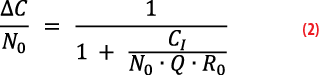
Figure 9 illustrates how the C/N0 would vary for distinct levels of transmitted power (PRF) i.e., 3.5 kW, 350 kW and 3500 kW (EIRP), and a noise power spectral density (N0) of -202.8 dBW/Hz. The dips in the curve indicate reduced signal quality due to decreased distance, aligning with the emitter’s position. It is worth noting the impact of interference is most prominent in the periods immediately preceding and following the satellite’s traversal of the zenith, rather than during its direct passage above the zenith. This observation underscores the temporal dynamics of interference effects on the carrier-to-noise ratio.
In addition to high emitter power levels, a very low emitter power level of 3.5kW inducing a C/N0 degradation of 1 dB was considered. As mentioned in [15], the use of 1-dB decrease in carrier-to-noise density ratio (C/N0) as the appropriate interference protection criterion (IPC) for GPS and other Radionavigation Satellite Systems (RNSS). [15] provides a brief explanation of the relationship between a (post-correlation) 1-dB drop in C/N and an interference-to-noise ratio (I/N) of–6 dB.
In typical operational GNSS space contexts, tracking thresholds are established at C/N0 levels near 25 dB-Hz. Considering a scenario with a nominal GNSS signal strength of 40 dB-Hz, coupled with a 25 dB interference loss, the receiver encounters a significant challenge in achieving robust tracking. Under these conditions, such a space receiver becomes more vulnerable to experiencing loss of lock in both code and phase domains, indicating a notable lack of resilience.


How can we mitigate the impact of interference on receiver performance?
Given the possibility of a very large emitter power of 3.5 MW and the consequent degradation of signal strength of 25 dB, SeRANIS may not continue to provide reliable positioning results. However, it is possible to implement robust tracking loops, allowing the receiver to provide continuous and accurate positioning results.
The principal objective of external aiding lies in acquiring velocity data by predicting the satellite’s orbital motion, which holds significant importance in carrier tracking with a diminished loop bandwidth (PLL bandwidth). By converting this velocity data into the line-of-sight, it becomes feasible to establish a Carrier-Doppler aiding in each channel, thereby delineating the line-of-sight domain between the user and the satellite. This Doppler-assisted carrier information can then be employed for code tracking, a phenomenon called Carrier-Doppler-aided Code tracking [16]. From [3], it is proven that incorporating Doppler aiding enhances the receiver’s resilience against interference and jamming. It is worth noting the SeRANIS satellite employs a very stable clock (a so-called ultra-stable oscillator) so the effects of clock jitter can be neglected.
As proof of this mitigation technique, Figure 10 shows the positional accuracy (comparing the position of SeRANIS under the event of jamming with a reference trajectory serving as ground truth) in the case of a completely unaided tracking loop. Figure 11 illustrates the obtained positional accuracy under the implementation of a Carrier-Doppler-aided code tracking loop. This comparison occurs under the case of a completely aided tracking loop, demonstrating both robustness and “dm-level” accuracy in the obtained position. In principle, this is a sophisticated tracking mechanism that capitalizes on carrier frequency information to counteract Doppler effects, thereby improving the precision and reliability of code tracking in various dynamic communication and navigation systems. A comparative analysis of various aiding mechanisms is provided in [3].
In addition to the outlined strategies, other mitigation measures exist for SeRANIS concerning signal filtering and/or nulling interference based on both LHCP and RHCP signals from zenith antenna 1.

Conclusion and Future Direction
This article delves into the critical realm of defending space-based receivers against jamming attacks, particularly focusing on interference within the GPS L1 frequency range for one of the ATHENE 1 satellite’s zenith antennas.
A small simulation framework provided valuable insights into the challenges posed by jamming attacks and verified the single-satellite single-pass over an emitter and processing the jamming signals in a GNSS receiver with the implementation of a Carrier-Doppler-aided Code tracking loop. The developed technique to mitigate the adverse effects of jamming has been proven to provide a higher degree of robustness as well as more accurate receiver positioning. The receiver exhibited robustness by converging to decimeter-level accuracy within the predicted 20-second convergence time. Notwithstanding, it remains necessary to ascertain whether these outcomes remain applicable when accounting for atmospheric effects and other sources of error in the simulation.
Looking ahead, further research endeavors could explore enhanced mitigation strategies to bolster resilience against jamming attacks. By continuing to advance our understanding of space-based interference detection and mitigation, we can fortify the integrity and reliability of GNSS services, ensuring their indispensable role in modern navigation systems.


Acknowledgements
This research is funded by dtec.bw– Digitalization and Technology Research Center of the Bundeswehr SeRANIS.
References
[1] E. Gill, J. Morton, P. Axelrad, D. M. Akos, M. Centrella, and S. Speretta, “Overview of Space-Capable Global Navigation Satellite Systems Receivers: Heritage, Status and the Trend towards Miniaturization,” Sensors, vol. 23, no. 17, Sep. 2023, doi: https://doi.org/10.3390/s23177648.
[2] Donatas Palavenis, “Moscow develops military space tech: should we take note? – analysis – LRT.” Accessed: Feb. 16, 2024. [Online]. Available: https://www.lrt.lt/en/news-in-english/19/1570739/moscow-develops-military-space-tech-should-we-take-note-analysis
[3] Sahana Bandagadde Umesha, Clovis Maia, Mohamed Bochkati, Jürgen Dampf, and Thomas Pany, “A Pre- and Post-correlation Comparative Analysis to Assess Resilience Against Jamming for GNSS Space Receivers,” presented at the 36th International Technical Meeting of the Satellite Division of The Institute of Navigation (ION GNSS+ 2023), Denver, Colorado, pp. 1544–1564.
[4] “SeRANIS – Multifunctional Satellite Laboratory | UniBw M | dtec.bw.” Accessed: Feb. 16, 2024. [Online]. Available: https://seranis.de/en/home-en/
[5] A. Kinzel et al., “Seamless Radio Access Network for Internet of Space (SeRANIS): New Space Mission for Research, Development, and In-Orbit Demonstration of Cutting-Edge Technologies,” in 73rd International Astronautical Congress (IAC), Paris: International Astronautical Federation (IAF), Sep. 2022. [Online]. Available: https://athene-forschung.unibw.de/85049?query=Knopp+F%C3%B6rstner&show_id=143331
[6] “LuxSpace -OHB Digital.” [Online]. Available: https://www.ohb-digital.de/expertise/firmen/luxspace
[7] Z. Clements, T. E. Humphreys, and P. Ellis, “Dual-Satellite Geolocation of Terrestrial GNSS Jammers from Low Earth Orbit,” presented at the 2023 IEEE/ION Position, Location and Navigation Symposium (PLANS), Monterey, CA, USA: IEEE, Apr. 2023. doi: https://doi.org/10.1109/PLANS53410.2023.10140058.
[8] “MuSNAT (Multi-Sensor Navigation Analysis Tool).” Institute of Space Technology and Space Applications (ISTA), Universitaet der Bundedswehr Muenchen (UniBwM). Accessed: Apr. 08, 2024. [Online]. Available: https://www.unibw.de/lrt9/lrt-9.2/software-packages/musnat
[9] T. Pany et al., “The Multi-Sensor Navigation Analysis Tool (MuSNAT) – Architecture, LiDAR, GPU/CPU GNSS Signal Processing,” in The Insitute of Navigation (ION GNSS+), Miami, Florida, Sep. 2019, pp. 4087–4115. doi: https://doi.org/10.33012/2019.17128.
[10] M. Arizabaleta et al., “Recent Enhancements of the Multi-Sensor Navigation Analysis Tool (MuSNAT),” in The Institute of Navigation (ION GNSS+), St. Louis, Missouri, Sep. 2021, pp. 2733–2753. doi: 10.33012/2021.17960.
[11] The MathWorks Inc., “Satellite Communications Toolbox.” The MathWorks Inc., Natick, Massachusetts, United States. [Online]. Available: https://de.mathworks.com/products/satellite-communications.html
[12] The MathWorks Inc., “MATLAB.” The MathWorks Inc., Natick, Massachusetts, United States. [Online]. Available: https://www.mathworks.com
[13] B. R. Rao, W. Kunysz, R. Fante, and K. McDonald, GPS/GNSS antennas. in Artech House GNSS technology and applications series. Boston London: Artech House, 2013.
[14] A. Meredov and S. Lindenmeier, “Circular Polarized Compact Dual Antenna Set for L-Band Space Applications,” presented at the Proceedings of the 53rd European Microwave Conference, Sep. 2023. doi: 10.23919/EuMC58039.2023.10290276.
[15] U.S. Air Force, “Background Paper on use of a 1-dB Decrease in C/N0 as GPS Interference Protection Criterion.” [Online]. Available: https://www.gps.gov/spectrum/ABC/1dB-background-paper.pdf
[16] Jong Hoon and T. Pany, “Signal Processing,” in Handbook of Global Navigation Satellite Systems, Springer, 2017, pp. 401–442. [Online]. Available: https://doi.org/10.1007/978-3-319-42928-1_14
Authors
Sahana Bandagadde Umesha works as a research associate at the Institute of Space Technology and Space Applications of the University of the Bundeswehr Munich. Her research activities include GNSS receiver technology, interference analysis, and aiding mechanisms for space receivers. She holds a master’s degree in Earth Oriented Space Science and Technology (ESPACE) from the Technical University of Munich, Germany.
Thomas Kraus is a research associate at the University of the Bundeswehr Munich and works for the satellite navigation unit LRT 9.2 of the Institute of Space Technology and Space Applications (ISTA). His research focuses on future receiver design offering a superior detection and mitigation capability of RF interferences. He has a master’s degree in electrical engineering from the Technical University of Darmstadt, Germany.
Nikolas Dütsch is a research associate at the University of the Bundeswehr Munich and works for the satellite navigation unit LRT 9.2 of the Institute of Space Technology and Space Applications (ISTA). His research focuses on the sensitive detection and geo-location of RF interference sources from low-Earth-orbit (LEO) satellites. He holds a master’s degree in electrical engineering from the Friedrich-Alexander-University of Erlangen/Nuremberg, Germany.
Dr. Clovis Maia has worked as a research associate at the University of the Bundeswehr Munich since 2022, where he has worked with software defined receivers for GNSS signal processing and positioning under electronic warfare conditions, as well as hybrid PNT technology with the use of LEO satellite constellations.
Prof. Thomas Pany is a full professor at Universität der Bundeswehr München at the faculty of aerospace engineering where he teaches satellite navigation. He focuses on GNSS/LTE/5G signal design and processing, software receivers and GNSS/INS/LiDAR fusion. He has about 200 publications including patents and one monography.


