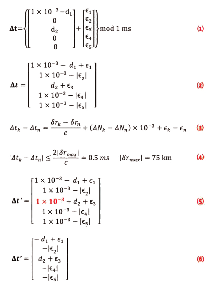
Q: Can you list all the properties of the carrier-smoothing filter?
A: Carrier-smoothing filters, also known as Hatch filters, are commonly used to reduce (“smooth”) the noise and multipath errors in pseudorange measurements by exploiting the high-precision relative distance information from carrier phase measurements. However, carrier-smoothing filters operate on more than just noise and multipath, and this article summarizes the response of such filters to all relevant inputs.
The GNSS carrier-smoothing filter is governed by the following finite difference equation
Equation (1) (see inset photo, above right, for article equations)
for n>0 where rsm[n] is the filter output at the n-th epoch, whereas rc[n] and rp[n] are the code and phase pseudoranges, respectively. For the initial condition when n = 0, rsm[n]= rc[n].
In this article we will analyze the case in which parameter M, which relates to the bandwidth of the filter (larger M gives more smoothing), is constant. Figure 1 (for all figures and tables, please see the photo at the top of this article) shows a block diagram of the carrier-smoothing system. We use the following fundamental signals: the impulse signal δ[n]=1 for n = 0 and 0 for n ≠ 0, and the step signal u[n]=1 for n ≥ 0 and 0 for n < 0. The output of the block with transfer function z-1 is x[n-1] when the input is x[n].
Taking into account the main errors, the code pseudorange can be written as
rc[n] = r[n] + cS[n] + cR[n] + T[n] + I[n] + wc[n] (2)
where r[n] is the true range between the satellite and the GNSS receiver, cS[n] is the error due to the bias of the satellite clock, cR[n] is the error due to the bias of the receiver clock, T[n] is the error due to the troposphere delay, I[n] is the error due to the ionosphere delay, wc[n] is the noise due to the receiver DLL (delay locked loop) jitter due to thermal noise and noise-like multipath. All the quantities are measured in meters.
The phase pseudorange can be written as
rp[n] = r[n] + cS[n] + cR[n] + T[n] + I[n] + N[n]λ + wp[n] (3)
where N[n] is the integer ambiguity, λ is the wavelength, and wp[n] is the noise due to the receiver PLL (phase locked loop) jitter plus the effect of multipath. The integer ambiguity should be constant N[n]=N0 during the satellite visibility, but we consider here that cycle slips may occur and therefore the integer ambiguity becomes a time-varying signal.
In general, the product of the carrier wavelength and the integer ambiguity, λN[n], can be written as
Equation (4)
where nk > 0 is the discrete-time at which the k-th cycle slip event occurs, dk the number of cycles in the slip (integer, positive or negative), Nc.s. is the number of cycle slip events in the observation time. Parameter N0 is the value of N[n] at n = 0, which can be set equal to zero, since it cancels out in (1) for n>0.
Both pseudoranges have a common term s[n] = r[n] + cs[n] + cR[n] + T[n]. They also have the term I[n] with opposite sign, and each one has its own noise component (wp[n] and wc[n]), which are statistically independent.
In the following sections, we analyze the outputs of the carrier-smoothing system when one and only one of the various components is present. The total system output is then given by the sum of all the individual outputs, thanks to the system’s linearity.
Tables 1–3 list all the relevant formulas and figures. Transfer functions are identified as Hx(z) (z complex number), impulse responses as hx[n] (n integer), step responses as ux[n] where x specifies the considered component. In the tables, Hx(f) is defined as Hx(f) = Hx(ej2πf) where f is the normalized frequency; the true frequency is f´ = f / T (in hertz) where T is the time interval between two subsequent epochs.
Common Component
For the common signal s[n], the system has just one input and one output, as shown in Figure 2. In this case we can evaluate the transfer function in the z-domain, as the cascade of two subsystems. The first subsystem is a finite impulse response (FIR) filter with transfer function:
Equation (5)
The second subsystem is instead an infinite impulse response (IIR) filter with the following transfer function
Equation (6)
and thus, the transfer function and impulse response of the entire system with input s[n] are, respectively,
Hs(z) = HFIR(z)HIIR(z) =1, hs[n] = δ[n] (7)
as also reported in (20) and (21) of Table 1. Thus, we have rsm,s[n] = s[n] * hs[n] = s[n], which means that the true range, the troposphere delay, and the terms due to the clock bias are present without alterations at the output of the filter.
Initial Condition
The initial condition can be interpreted as an impulse rc[0]δ[n] which enters the low-pass IIR filter and provides the output rsm,i.c.[n] = rc[0]hi.c.[n], where hi.c.[n] and its plots for M=30 and 100 are reported in Table 2: equation (28) and the figure at its right. We can see that a long transient exists, which has theoretically an infinite duration but can be quantified through the partial energy Ei.c.[n]. It is possible to show that
Equation (8)
with Ei.c. being the total energy of hi.c.[n] for n → ∞. The impulse response reaches 98 percent of its total energy after approximately 2M samples. We can therefore state that, according to the 98 percent criterion, the transient ends at the discrete time 2M.
Cycle Slip
Let us consider the effects of just one cycle slip event, i.e., λN[n] = λd0u[n – n0] in (4). The transfer function Hc.s.(z) of the system with input λN[n] and output rsm,c.s[n] is given in (29) of Table 2. The response to λd0u[n – n0] is the inverse z-transform of Rsm,c.s[z] = Hc.s(z)λd0z-n0 / (1- z-1).
Equation (9)
The figure on the right of (31) in Table 2 shows the step response for M=30 and 100: as M increases, the coefficient gets closer to 1, and the duration of rsm,c.s[n] increases. Using the 98 percent criterion, the transient is over 2M samples after the occurrence of the cycle slip.
Ionosphere Component
The analysis of the ionosphere component can be performed using the block diagram of Figure 3. In this case, the first filter has transfer function
Equation (10)
while the second filter is again the same IIR filter of Figure 2 described by equation (6).
Therefore, the transfer function for the ionosphere component I[n] is Hiono(z) = HFIR,iono(z)HIIR(z), given in (22) of Table 1. Equation (25) in Table 1 gives the corresponding impulse response hiono[n], with plots for M=30 and 100 on its right. Then the carrier-smoothing filter output due to the ionosphere can be written as
rsm,I[n] = I[n]*hiono[n] (11)
which unfortunately does not provide much information; so, some approximations are necessary. Filter Hiono(z) has a zero, (M-1)/(M-2), and a pole, (M-1)/M, very close to each other. The system then tends to behave as an all-pass filter, as shown in the figure on the right of (23) in Table 1, where the modulus of the transfer function Hiono(f) = Hiono(exp(j2πf)) is plotted versus the normalized frequency f. The group delay of the system is defined as
Equation (12)
where φiono(f) is the phase of Hiono(f), shown in the figure on the right of (24) in Table 1. We can show that, for small values of f,
Equation (13)
having defined a=(M-1)/(M-2) and b=(M-1)/M.
In nominal conditions, the ionosphere component I[n] changes slowly, which means that its bandwidth is very small, and we can approximate the transfer function in the frequency domain as
Hiono(f) ⋍ Miono exp[−j2πτi f]
where Miono = 1 is the magnitude of Hiono(f) at f = 0, and τi is the group delay θiono(f) at f = 0:
Equation (14)
Then, for a sufficiently slow ionosphere component I[n], the output of the carrier-smoothing filter is approximately equal to rsm,I[n] I[n – 2(M-1)] with a delay τi = 2(M-1), which decreases as M decreases.
Noise Components
A discrete-time white Gaussian noise process win[n], with zero mean and variance σw2, which enters a filter with impulse response h[n], generates an output process wout[n] that is no longer white, but still Gaussian, with zero mean and with variance
Equation (15)
Code Pseudorange Noise. Code pseudorange noise generates an output process rsm,c.n.[n] which is obtained by using wc[n] as input of the filter with impulse response hc[n]= hIIR[n]/M. Using (15) and the total energy (obtained from (8) for n → ∞) we get the output variance σ2c,out:
Equation (16)
where σc2 is the variance of wc[n]. The figure on the right of (32) in Table 3 shows how σ2c,out decreases to zero as M increases. This is the “smoothing” aspect of the filter.
Phase Pseudorange Noise. Phase pseudorange noise generates an output process rsm,p.n.[n] which is obtained by using wp[n] as input of the filter with impulse response hp[n] = (M-1){hIIR[n]-hIIR[n-1]/M}, which can be written as follows:
Equation (17)
where σp2 is the variance of wp[n]. The figure on the right of (33) in Table 3 shows how σ2p,out increases with M with an asymptotic value equal to σp2, which means that the system tends to behave as an all-pass filter as M increases (although since σp is typically much smaller than σc, this is not a major concern).
Summary of the Results
In the presence of all the errors, the signal at the output of the carrier-smoothing filter is then
rsm[n] = s[n] + rsm,i.c[n] + rsm,c.s.[n] + rsm,c.n.[n] + rsm,p.s[n] + rsm,I[n] (18)
Table 1 lists the results valid for the common and ionosphere components s[n] and I[n]. Table 2 refers to effects due to the initial condition and the cycle slips. Table 3 summarizes the results obtained for the noise and multipath inputs wc[n] and wp[n].
On the one hand, we see that larger values of M decrease the output noise variance due to code pseudorange, but on the other hand these larger values increase the duration of transients in the presence of cycle slips; so, a compromise must be found. The total noise variance at the output of the carrier-smoothing filter is
Equation (19)
With this value of M, the noise variance at the output of the smoothing filter is equal to 2σp2 and the transient durations are reasonably short. However, if cycle slips are frequent, then transients are the dominating error and M should be chosen, taking into consideration the probability and magnitude of undetectable cycle slips.


