Long Life Cryocoolers Best-in-Class Infrared Performance All From One Dependable Supplier
Sponsored by Teledyne FLIR
CRYOCOOLED INFRARED SYSTEM RELIABILITY
Teledyne FLIR understands the criticality of our user’s mission readiness and the
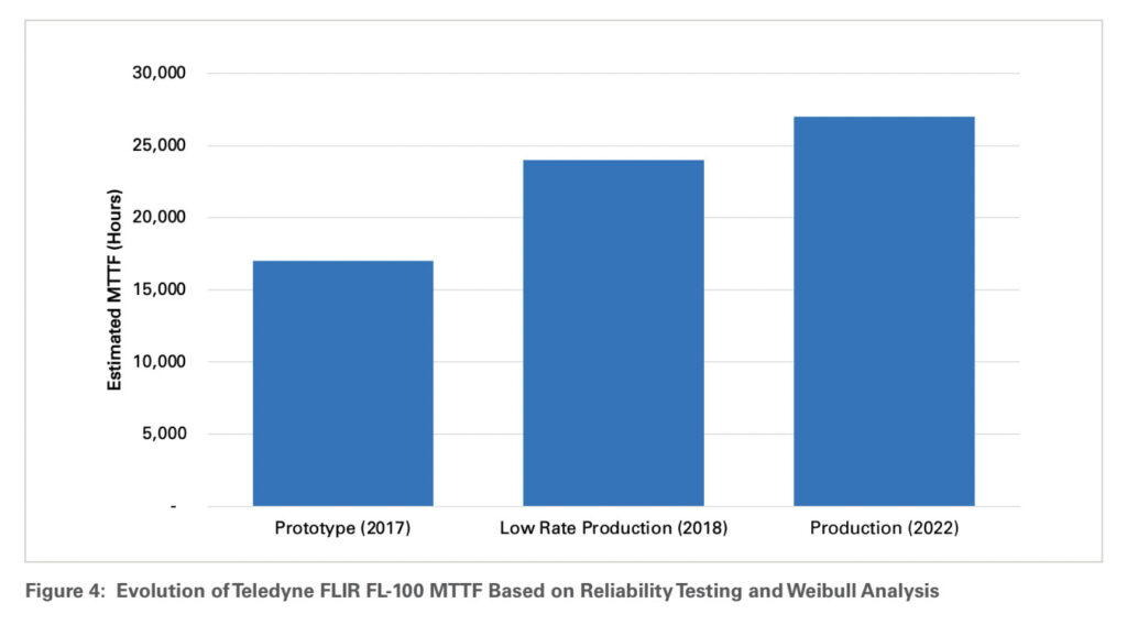
importance of long, maintenance-free infrared (IR) system operation. Cooled mid wavelength infrared (MWIR) cooled camera modules must be designed, tested, and manufactured to meet rigorous environment and reliability requirements. This includes military temperature ranges and high shock and vibration levels. Recognizing that reliability and operational lifetime are typically determined by the operation and lifetime of the cryo-cooler, Teledyne FLIR developed, tested, and manufactures a ruggedized, long-life, linear cryocooler to build size, weight, and power (SWaP) optimized MWIR camera modules with market-leading operational lifetimes. Based on lifetime tests and Weibull analysis, the estimated mean time to failure (MTTF) of the Teledyne FLIR FL-100 cryocooler has increased from approximately 17,000 hours at prototype introduction to approximately 27,000 hours for current production units with a target lifetime of greater than 30,000 hours.
This paper describes the types and history of cryocoolers, explains several common misunderstandings about their reliability, and covers what Teledyne FLIR is doing to improve cryocooler lifetimes.
INFRARED CAMERA MODULE AND SYSTEM INTRODUCTION
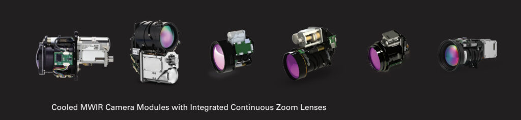
Teledyne FLIR designs and manufactures many different IR imaging systems. The Neutrino® product portfolio includes high performance MWIR camera modules, and several Neutrino IS series models that integrate the MWIR camera module with a continuous zoom (CZ) lens assembly. These cryocooled, MWIR camera modules or systems come in a variety of model configurations, each incorporating similar components, but with the slight variations to optimize performance versus size, weight, and power. The following components and functions are included in MWIR camera modules and systems.
• Focal Plane Array (FPA): The FPA is comprised of a detector hybridized to a read out integrated circuit (ROIC). The detector converts MWIR photons to an electrical current. The ROIC reads the current and provides an analog voltage or digital signal that is proportional to the number of photons at the detector. Presently InSb and most HgCdTe detectors operate best at cryogenic temperatures (e.g., 77K). These low temperatures require significant cooling capacity which translates into a larger cooler size, increased weight, and increased power. Hot MWIR Barrier Infrared (e.g., T2SL) detectors are considered high operating temperature (HOT) at approximately 120K operation and therefore require less cooling capacity. These higher temperatures mean smaller cooler size, lower weight, less power required, reduced time to image, and increased cooler lifetime.
• Dewar: The Dewar is a vacuum package containing the FPA, coldshield (defines the f/number and prevents stray light) and the coldfilter (determines the wavelengths of the photons at the detector). The electrical signals between the ROIC and the camera electronics are provided via hermetically sealed feedthroughs. Faster f/numbers increase performance, but also increase the size of the optics.
• Cryocooler: Mechanical cryocoolers provide extended duration cooling to IR FPAs. Modern designs integrate directly to the Dewar as part of an Integrated Dewar Cooler Assembly (IDCA). They are also integrated with and controlled by camera electronics, generally through a dedicated cooler control electronics module.
• Camera Electronics: The camera electronics may include multiple printed circuit board assemblies (PCBAs) to accomplish the following functionality.
- Sensor Interface Electronics includes power, clocks, and timing logic to the FPA and, if necessary, digitization of the FPA outputs.
- User Interface Electronics include signal-processing for noise filtering, image enhancement, operational logic, and camera functions including the overarching command and control interface and video output standards for the user interface.
- Cooler Controller Electronics control the cooler operation to cooldown and maintains the FPA/Dewar temperature chosen to optimize power and image quality.
- Optics Controller Electronics control the opto-mechanical lens assembly, maintain continuously athermalized focus over zoom, and support the user interface.
• Continuous (CZ) Optics: A CZ optic can be integrated to provide the final imaging solution. The CZ opto-mechanical lens assembly includes the optical assembly, mechanical packaging, focus and zoom motors, and temperature sensors.
CRYOCOOLERS PAST AND PRESENT
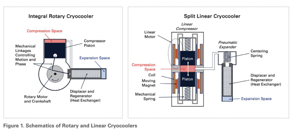
Stirling cryocoolers for tactical applications are almost always either rotary or linear types. Rotary coolers use a crankshaft attached to their moving piston and displacer. This arrangement allows precise control of the relative phase angle of these components but introduces side forces from the crankshaft linkages that can impact lifetime and reliability. In contrast, linear coolers are driven by voice coil type actuators with minimal side forces and that rely on pneumatic drive and tuning to control the phase of the displacer relative to the compressor.
Rotary coolers were the most common cooler type in early cooled sensors. Due to their precise, mechanical phase control mechanism and the fact that the phase does not vary with frequency (RPM), rotary coolers have historically had higher efficiency and faster cooldown times than linear coolers. The drawback for these coolers has traditionally been lifetime due to the increased seal wear caused by the side forces generated by their mechanical crankshaft linkages. However, modern designs have greatly improved reliability with some manufacturers claiming lifetimes of 15,000 to 30,000 hours. Another drawback for rotary coolers has typically been exported vibration from their unbalanced crank mechanisms, which can cause jitter for sensitive systems and in turn can lead to an increased SWaP footprint and lower reliability if stabilization is needed. Generation of acoustic noise is also an issue with many rotary coolers.
Linear cryocoolers have become the most common cooler type for newer systems due to their significantly longer lifetimes and lower exported vibration. The linear cryocooler mechanism does typically drive slightly larger size for a given cooling capacity and slightly longer cooldown times. Because they are tuned to operate near resonance, linear coolers are limited to a single operating frequency. Their input power can be modulated through the amplitude of the compressor pistons, but the inability to increase frequency during cooldown results in longer cooldown times than what can be achieved using rotary coolers. For modern linear coolers, lifetimes of 20,000 to 30,000 hours are becoming expected.
The pulse tube cooler is a special type of linear Stirling cooler in which the moving Stirling displacer in the cold finger is replaced with an expander containing no moving parts. A column of gas replaces the physical Stirling displacer. This “gas piston” is paired with a stationary regenerator and a phase shifting mechanism to control the mass flow relative to the oscillatory pressure. This phase control mechanism is more sensitive to operating conditions than the pneumatic tuning of the standard linear Stirling cooler, leading to lower efficiency at operating points away from the design point. Cooldown time is especially impacted and is generally significantly longer than other coolers of similar capacities. The separation of the regenerator from the pulse tube, which becomes the effective displacer, leads to a larger cold finger. Pulse tubes are also prone to orientation sensitivity, particularly in high-G environments. These drawbacks have prevented pulse tube coolers from being used in most tactical applications, despite their advantage in lifetime. Paired with a non-contacting flexure bearing compressor, pulse tube coolers can achieve lifetimes greater than 100,000 hours.
CRYOCOOLER RELIABILITY BASICS AND MISCONCEPTIONS
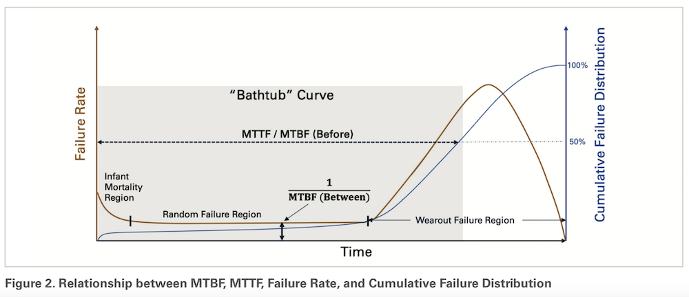
Reliability for cooled camera modules and cryocoolers is often reported in terms of either mean time between failures (MTBF) or mean time to failure (MTTF). While the terms sound similar, there are several important distinctions. Generally, MTBF is applied to repairable systems while MTTF is used for systems which cannot be repaired. More importantly, the two metrics are defined differently and do not compare directly to one another. To add further ambiguity, sometimes MTTF is referred to as mean time before failure and abbreviated as MTBF. These metrics are shown with typical failure rate and cumulative failure distribution curves in Figure 2.
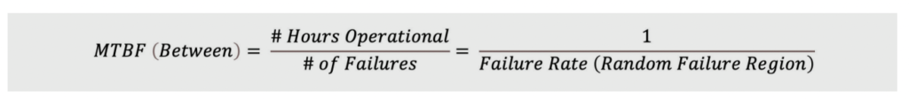
The MTBF (between) metric assumes a constant rate of failures for a component, which is a good assumption for components not subject to mechanical wear (e.g., electronics). It is equivalent to the inverse of the random failure rate of the component and is often defined as (#hours operational) / (# failures) for a population of interest. MTBF was often used historically for cryocoolers and cooled IR cameras, particularly when cryocoolers wore out quickly and were frequently replaced. For more modern cryocoolers, the failure rate prior to wear out is generally very low and the MTBF is therefore very high. Because it does not account for mechanical wear out of the cryocooler and is only focused on the random failure rate prior to wear out, the calculated MTBF of a cryocooler will often significantly exceed its MTTF or expected lifetime.
Currently, cryocooler lifetime estimates are more often presented in terms of MTTF and calculated using Weibull statistics. The most used Weibull distribution has two parameters, a shape parameter indicative of the amount of wear in the system and a lifetime parameter representing the point at which 63% of the population will have failed. The two parameter Weibull distribution representing the failure rate vs. time is shown below.
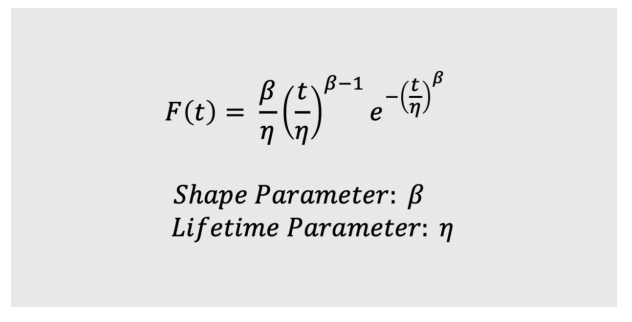
The MTTF, defined as the time at which 50% of units in the population will have failed, can be calculated from a sample of units using statistical analysis software. This methodology is now used by the majority of cryocooler manufacturers, however many report the lifetime parameter of their distribution (63% failure) rather than the true MTTF (50% failure). Because this method accounts for wear out of the mechanical coolers, it provides a better estimate of their true useful lifetime. Teledyne FLIR estimates cryocooler lifetime for our products by fitting our life test data to a Weibull distribution and calculating the MTTF (50% failure) point of the population.
While cryocooler MTTF inputs are helpful to establish IR cryocooled system reliability, there is an important caveat for Teledyne FLIR’s IR camera modules and systems. Cryocoolers are designed in as a factory-replaceable component within the system. A worn out cryo-cooler can be easily replaced at our factory meaning the IR system should be seen as serviceable multiple times if necessary and thereby offering an extended infrared system operational life.
CRYOCOOLER RELIABILITY IMPROVEMENTS AT TELEDYNE FLIR
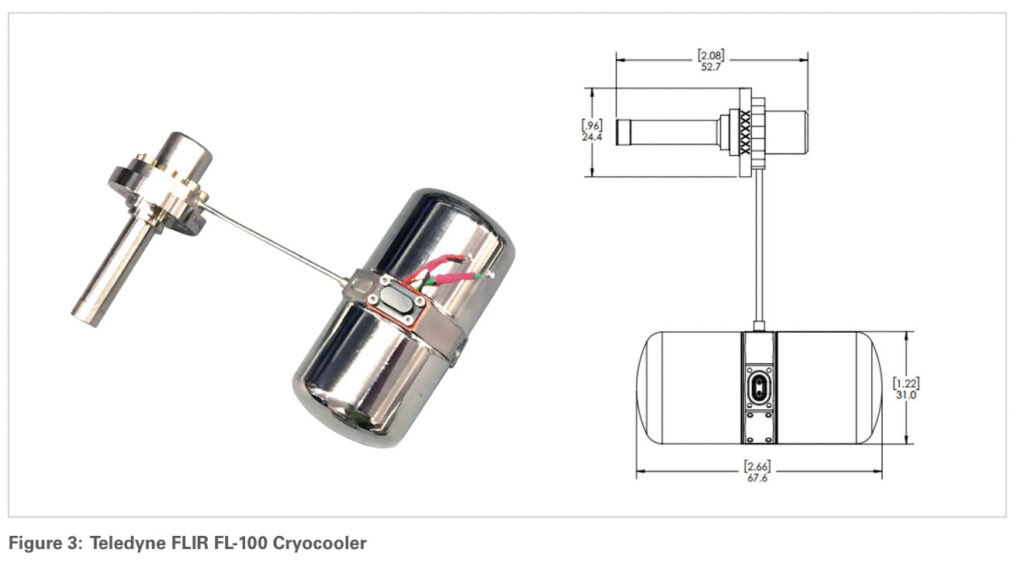
Operational readiness and long, maintenance-free operation are critical for IR system missions. Teledyne FLIR developed a ruggedized, long-life, linear cryocooler as part of the SWaP optimized Neutrino® cooled MWIR camera modules. The FL-100 linear cryocooler shown in Figure 3 is not only best-in-class from a performance perspective, but it also has an estimated operating life over 27,000 hours (MTTF) based on lifetime tests and the Weibull distribution.
The FL-100 design has undergone continuous improvement efforts since its introduction in 2018. Multiple friction reducing and tolerance improvements have been made resulting in increased lifetime and cooling capacity. Process innovations, focused mainly on the quality of the rubbing seals and the alignment of the moving components, also contributed significantly in improving lifetime. The impact of these improvements on the reliability of the FL-100 have been quantified through Teledyne FLIR’s cryocooler reliability testing program. Additional improvements are in validation targeting a MTTF of greater than 30,000 hours.
Teledyne FLIR performs ongoing reliability cryocooler testing for the dual purposes of verifying and improving reliability. Testing is comprised of both industry standard testing following the US Army Standard Advanced Dewar Assembly (SADA) life test profile and accelerated lifetime testing (ALT) incorporating several accelerating stresses. The data collected enables translation of the accelerated test results into SADA equivalent lifetimes. The FL-100 test facility has a capacity for 26 coolers with 8 dedicated to the SADA profile and 18 undergoing ALT. New units are added as testing stations become available, allowing verification of the performance of current production and evaluation of the process and design improvements. Based on this life testing program and Weibull analysis, the estimated MTTF of the FL-100 cryocooler has increased from approximately 17,000 hours at prototyping introduction to approximately 27,000 hours for current production units.
TELEDYNE FLIR FL-100 SUMMARY
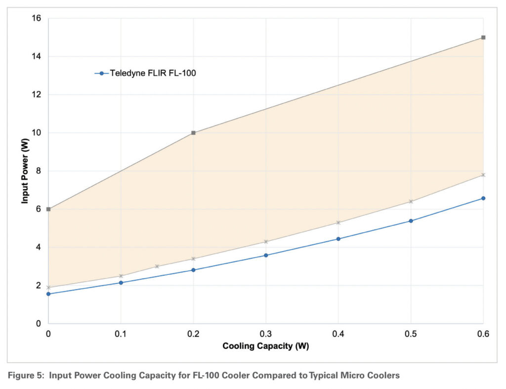
Cryocooler reliability in varying environments is often scaled by the input power requirements of a given application. In this way, estimated lifetimes in a standard environment (e.g., SADA profile) can be translated to a customer use case via normalization by Watt-hours. For this reason, a more efficient cryocooler generally has a longer lifetime, particularly in stressing applications.
In addition to category leading reliability, the FL-100 was designed to provide efficient cooling capacity to input power. Figure 5 compares cooling performance curves for the FL-100 and five currently available linear coolers from several suppliers with data used from public sources including datasheets and published papers. The FL 100 provides at least a 20% improvement and up to a 2x improvement in input power to cooling capacity when compared to similar linear coolers.
Linear cryocoolers have become the most common cooler type for newer systems due to their significantly longer lifetimes and lower exported vibration. For modern linear coolers, lifetimes of 20,000 to 30,000 hours are becoming expected. The Teledyne FLIR FL-100 linear cryocooler has an approximate MTTF of 27,000 hours and with ongoing product improvement is targeted to surpass 30,000 hours MTTF. It is integrated into the recently released, SWaP-optimized 640 x 512 resolution Neutrino LC and 1280 x 1024 resolution Neutrino SX8 cooled MWIR camera modules as well as in the Neutrino IS series of VGA and SXGA MWIR camera modules with various CZ lens assemblies. As a reliable and replaceable component, the FL-100 allows extended lifetime for the Neutrino portfolio.
Learn more at www.flir.com/neutrino.