Multi-antenna carrier-phase differential GNSS (CDGNSS)-based pose (position and orientation) estimation aided by monocular visual measurements and a smartphone-grade inertial sensor form the core of a system designed for micro aerial vehicles. It can be applied generally for low-cost, lightweight, high-accuracy, geo-referenced pose estimation.
JAMES E. YODER, PETER A. IANNUCCI, LAKSHAY NARULA AND TODD E. HUMPHREYS
RADIONAVIGATION LABORATORY, THE UNIVERSITY OF TEXAS AT AUSTIN
Micro aerial vehicles (MAVs) are increasingly being used for applications such as 3D mapping that require both:
• Precise pose (position and orientation) knowledge relative to a global coordinate system fixed to the Earth’s surface, and
• Close-in maneuvers to ensure high resolution of the area being mapped.
A global coordinate system is essential for applications such as automated infrastructure inspection, 3D modeling of buildings, disaster recovery or search and rescue and open-world virtual reality, in which mapping data from the MAV is consumed by other, possibly automated, agents, potentially long after the initial mapping process.
Carrier-phase differential GNSS (CDGNSS) techniques such as real-time kinematic (RTK) positioning can offer centimeter-accurate positioning accuracy, and so serve as an excellent anchor for globally-referenced pose estimation. However, such accuracy is only achieved robustly and instantaneously when so-called carrier phase ambiguities are resolved to their integer values. Confident ambiguity resolution depends on a large number (e.g., 12+) of participating low-multipath GNSS signals, or on a tight prior position estimate. But as a mapping MAV passes close to buildings, under overhanging rooftops, or around foliage, GNSS signal blockage and multipath effects become severe, limiting the availability of CDGNSS unaided by inertial sensing. Users of mapping MAVs therefore currently tend to avoid altogether areas where GNSS signals might be obstructed.
The MAV platform also places unique constraints on navigation systems: onboard compute is restricted by size, weight, and power limitations; the lively system dynamics of MAVs require low-latency measurement and estimation; and, in many cases, MAVs may only feature low-cost consumer-grade cameras and inertial measurement units (IMUs).
This article describes a method for improving CDGNSS performance via tight coupling with a visual-inertial pose estimator. A CDGNSS system is defined herein as tightly coupled with visual and inertial sensing if the latter aid in resolving CDGNSS integer ambiguities. A loosely coupled CDGNSS system, in contrast, is based on a standalone CDGNSS estimator that operates without aiding from other sensors. Information in a loosely-coupled system only flows one way, from the CDGNSS estimator to the downstream estimators.
Visual and inertial measurements enable robust operation despite GNSS degradation by constraining uncertainty in the dynamics propagation, which improves fixed-integer CDGNSS availability and reliability in areas with limited sky visibility.
No prior work has demonstrated an increased CDGNSS integer fixing rate when incorporating visual measurements with smartphone-grade inertial sensing. A central pose estimation filter receives measurements from separate CDGNSS position and attitude estimators, visual feature measurements based on the ROVIO measurement model proposed by Bloesch et al., and inertial measurements. The filter’s pose estimates are fed back as a prior for CDGNSS integer fixing. A performance analysis under both simulated and real-world GNSS degradation shows that visual measurements greatly increase the availability and accuracy of low-cost inertial-aided CDGNSS pose estimation.
The primary contribution of this article is the incorporation of visual measurements into a tightly-coupled multi-antenna CDGNSS-inertial pose estimator using a smartphone-grade IMU and camera. To best of the authors’ knowledge, this article provides the first demonstration of an increased RTK integer fix rate using visual-inertial aiding with smartphone-grade sensors.
Platform, Coordinate Frames, Notation
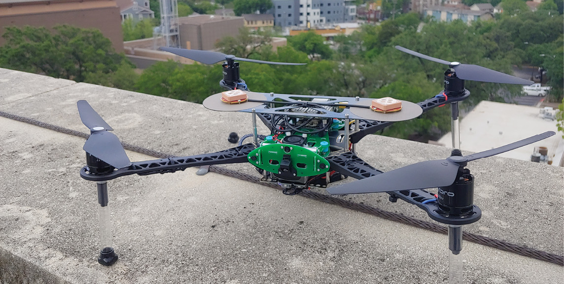
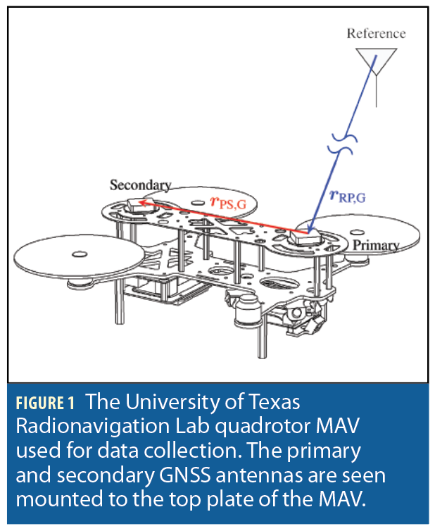
The reference MAV platform (Figure 1), is a quadrotor MAV featuring two low-cost L1-only GNSS antennas connected to a custom GNSS frontend. The frontend provides raw intermediate frequency (IF) samples that are processed by an advanced software-defined GNSS receiver running onboard the MAV. The software-defined GNSS receiver provides GNSS observables from GPS, Galileo, and satellite-based augmentation system (SBAS) constellations. Imagery is collected by a monocular 640×480 globally-shuttered camera running at 30 Hz. A smartphone-grade MEMS IMU (a Bosch BMX055) integrated with the GNSS frontend provides inertial measurements that are hardware timestamped with the GNSS receiver sample clock. The two GNSS antennas are referred to as the primary and secondary antennas.
Measurements and estimates are referenced to the following coordinate frames:
G: WGS-84 Earth Centered Earth Fixed (ECEF) frame.
W: “World” frame, a quasi-inertial East-North-Up (ENU) frame fixed to the Earth’s surface and centered at the RTK reference antenna’s phase center.
B: “Body” frame, centered at the primary GNSS antenna’s phase center and fixed to the quadrotor body.
U: “IMU” frame, centered at the IMU’s accelerometer triad and fixed to the quadrotor body.
C: “Camera” frame, centered at the optical center of the camera. Its X and Y axes are aligned with the X and Y pixel axes on the camera’s focal plane, and its Z axis points outwards towards the center of the camera’s view.

Federated Estimation Architecture
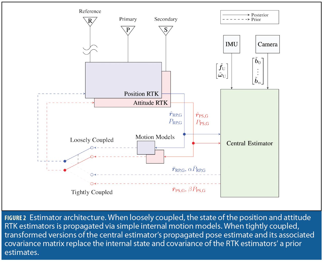
This work explores the coupling of discrete RTK estimators with a central pose estimator incorporating visual-inertial measurements. The central pose estimator is implemented as an unscented Kalman filter (UKF). As shown in Figure 2, the central estimator receives measurements from a smartphone-grade IMU, a monocular camera, and two independent single-baseline RTK estimators, referred to as the position and attitude RTK estimators. The position RTK estimator produces a single-baseline RTK solution between the MAV’s primary GNSS antenna and a fixed reference antenna with a pre-surveyed location. The attitude RTK estimator produces an RTK solution between the MAV’s primary and secondary GNSS antennas that is constrained by the known baseline length between the two antennas.
When operating in the loosely-coupled mode, the RTK estimators are unaided; that is, they provide position and attitude measurements to the central pose estimator but do not ingest any inertial or vision measurements to aid in producing RTK solutions.
When operating in the tightly-coupled mode, the central estimator’s output is taken as the prior for the RTK estimators: transformed versions of the central estimator’s propagated pose estimate and its associated covariance matrix replace the internal state and covariance of the RTK estimators’ a priori estimates. In this way, the central pose estimator provides a prior constraint on the RTK solutions, aiding the integer ambiguity resolution process.
This federated architecture, in which discrete estimators pass data back and forth, is suboptimal in terms of estimation performance and consistency compared to an “all-in-one” pose estimation filter that directly takes in GNSS pseudorange and carrier phase observables. Seeding the RTK estimators with the central pose estimate risks introducing unmodeled correlations between the pose estimator’s state errors and errors in the measurements it receives from the RTK estimators. However, this “loopy inference” is mitigated by the fact that double-difference carrier phase measurements are millimeter-precise compared to the decimeter-level precision of the pose-estimator-provided prior position. Such precision asymmetry implies that, when conditioned on correct integer ambiguities, the RTK estimators’ solution errors are dominated by carrier phase multipath, which is uncorrelated with the pose estimator’s state errors. In practice, the precision asymmetry is magnified by scaling the a priori covariance matrices PRP,G and PPS,G sent from the pose estimator to the RTK estimators with scalar inflation factors α and β, respectively (see Figure 2).
The integer-conditioning-induced decorrelation breaks down as the number of double-difference carrier phase measurements drops below 3, at which point the 3-dimensional position state becomes truly unobservable via GNSS measurements alone. When this occurs, the returned measurements contain information solely from the prior along any unobservable directions, leading to estimator inconsistency. To avoid this, the pose estimator does not ingest RTK measurements made with fewer than 3 double-difference measurements. This restriction has negligible effect in practice, as situations with one or two double-difference measurements are typically transient in nature; visual-inertial positioning easily covers the gap.
Of course, if ambiguities are incorrectly resolved, substantial correlation can build up between the RTK solution errors and the pose estimator state errors. Hence, extracting good performance from this paper’s federated tight coupling scheme demands careful aperture testing to validate candidate CDGNSS integer fixes. The integer fixing logic adopts a layered approach of signal selection, pseudorange-based innovations testing, and a controlled-failed-fixing-rate integer acceptance test.
The federated estimation architecture, although suboptimal, has the virtue of being simple to implement and diagnose and can draw on existing well-tested RTK estimators. Moreover, it enables switching back-and-forth between loose and tight coupling, as illustrated in Figure 2, which allows for convenient examination of the benefits of tight coupling. Finally, it manages to deliver impressive results compared to loose coupling, as will be shown, and so serves as a valuable stepping stone to future work in more complete tight coupling.

CDGNSS Estimators
Two independent RTK solutions are maintained by the RTK estimators: a position solution, rRP,W representing a vector pointing from the fixed RTK reference station to the MAV’s primary GNSS antenna, and an attitude solution, rPS,W representing a vector pointing from the MAV’s primary to its secondary onboard GNSS antennas, which provides globally-referenced pitch and yaw information. The attitude solution is constrained to the known baseline length, which is approximately one wavelength at the GNSS L1 frequency.
Having two independent RTK estimators is suboptimal as they do not account for the correlation in measurements due to the shared antenna in the two RTK baselines. However, independent RTK estimators are simpler to develop and maintain, and the configuration parameters of each RTK estimator, such as elevation masks, integer aperture test thresholds, and outlier exclusion parameters, can be tuned independently, which is beneficial as the baseline constraint on the attitude estimator allows much looser thresholds for equivalent fixing performance.
Outlier Rejection. Multipath and diffraction effects in urban environments cause frequent corruption of GNSS observables. A two-tiered strategy mitigates these outliers. First, a set of heuristics is applied to screen incoming observables and filter out measurements likely to be outliers. This screening applies thresholds for carrier-to-noise ratio, minimum satellite elevation, and a phase lock statistic calculated by the GNSS measurement engine. Measurements which do not pass this screening are discarded. Next, the filter applies a χ2-type innovations test to each incoming batch of double-difference measurements. If this test is failed, or if ambiguity resolution fails, the solution is iteratively re-attempted while excluding single measurements. This scheme has been shown to perform well in real-world urban positioning tests.
Integer Ambiguity Resolution. At every measurement epoch, a real-valued (float) solution is first attempted based on the position prior in the filter state and double-difference pseudorange measurements. In the loosely-coupled mode, this position prior is propagated from the previous RTK estimator solution using a simple nearly-constant-velocity motion model. In the tightly-coupled mode, this position prior is extracted from the state of the central pose estimator.
Next, integer ambiguity resolution is attempted using integer least squares (ILS) and validated via an integer aperture test with a predetermined failed fixing rate. For the attitude RTK estimator, the known baseline length between the two antennas is used as an additional constraint in the ILS search process.
The RTK estimators apply a single-epoch integer ambiguity resolution strategy. At every measurement epoch, after performing an ILS solution, the integer components of the RTK estimator state are discarded—by marginalization in the case of a float solution, or by conditioning on the integer state in the case of a fixed solution. This makes the estimators insensitive to cycle slips, which is critical to achieving high RTK availability and reliability in an urban environment, when signal degradations and outages are extremely frequent.
Central Pose Estimator
The central pose estimator is implemented as a UKF. Position and attitude RTK solutions and pixel intensity measurements of tracked visual features are ingested in the measurement update step, and IMU angular rate and specific force measurements are applied to propagate the filter state forward in time.
A detailed section from the original conference paper is omitted here for space reasons. To access it, see the Acknowledgments section at the end. This section covers filter overview and state parameterization, IMU bias sector, vision sector, IMU measurements, state propagation, rigid-body sector, CDGNSS measurements, visual measurements and outlier exclusion. It defines several variables and contains a range of equations.
Experimental Results and Analysis
The following subsections analyze the system’s performance on datasets containing simulated and real-world GNSS measurement degradations. For each of the datasets introduced below, the system was run in four modes, which are described in the figures and tables with the following abbreviations:
LC I: loosely-coupled mode with only RTK and inertial measurements;
LC V+I: loosely-coupled with RTK, visual, and inertial measurements;
TC I: tightly-coupled with only RTK and inertial measurements;
TC V+I: tightly-coupled with RTK, visual, and inertial measurements.
Simulated GNSS Degradations
For the results here, data from the sensors on board the MAV were collected from an area with a clear view of the sky. The loosely-coupled RTK-and-inertial pose solutions from these runs were taken as “truth,” as they had a large number of high-quality double-difference measurements available with high integer aperture test statistics. Next, artificial GNSS signal outages were introduced in the processing pipeline, temporarily excluding some or all of the received GNSS signals from processing. These artificial outages were used to evaluate the system’s positioning accuracy and ability to retain an RTK fix in degraded GNSS conditions. The outage pattern, roughly simulating passages below an occluding structure, consisted of 10 seconds of restriction to 6 double-difference measurements, 10 seconds of zero measurements, another 10 seconds of restriction to 6 measurements, followed by 5 seconds of no degradation before repeating.
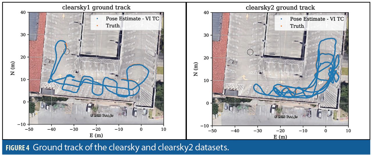
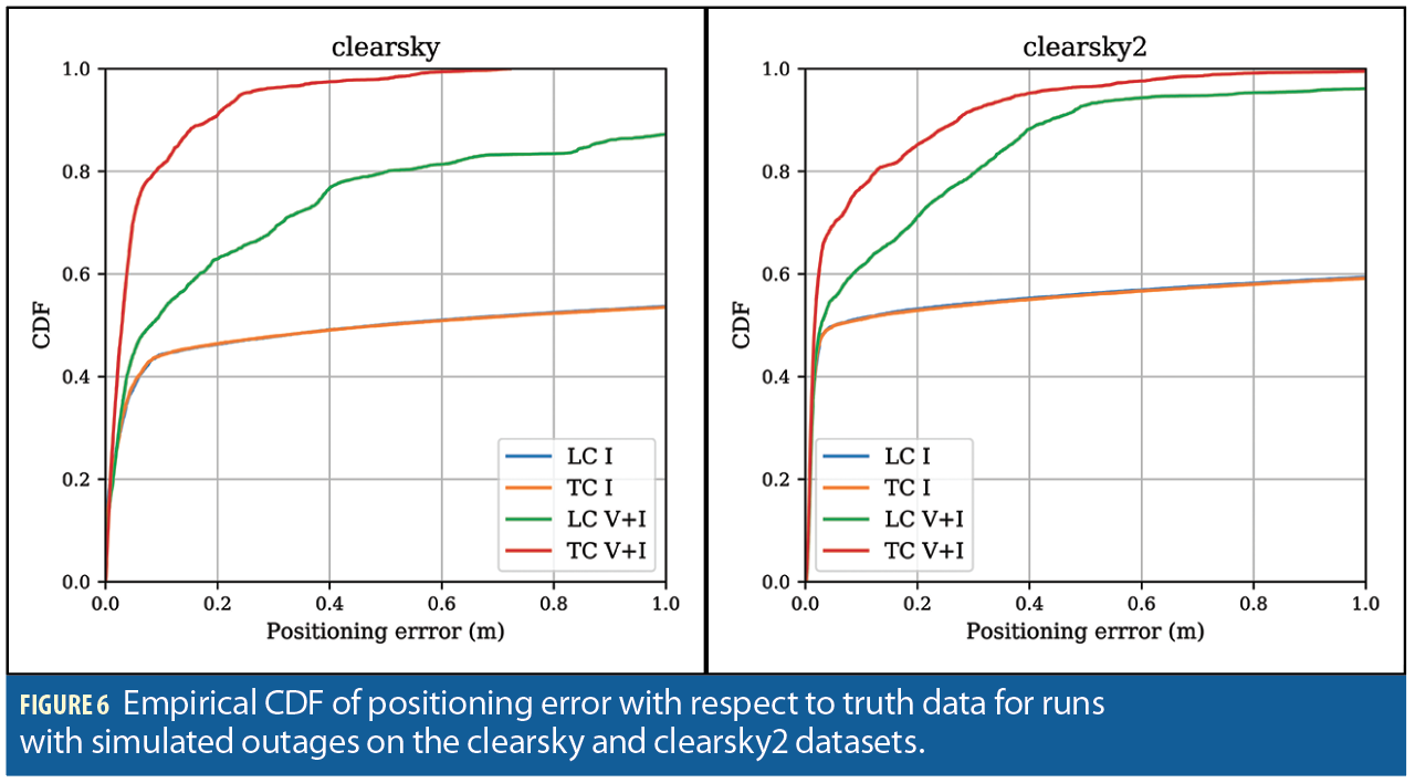
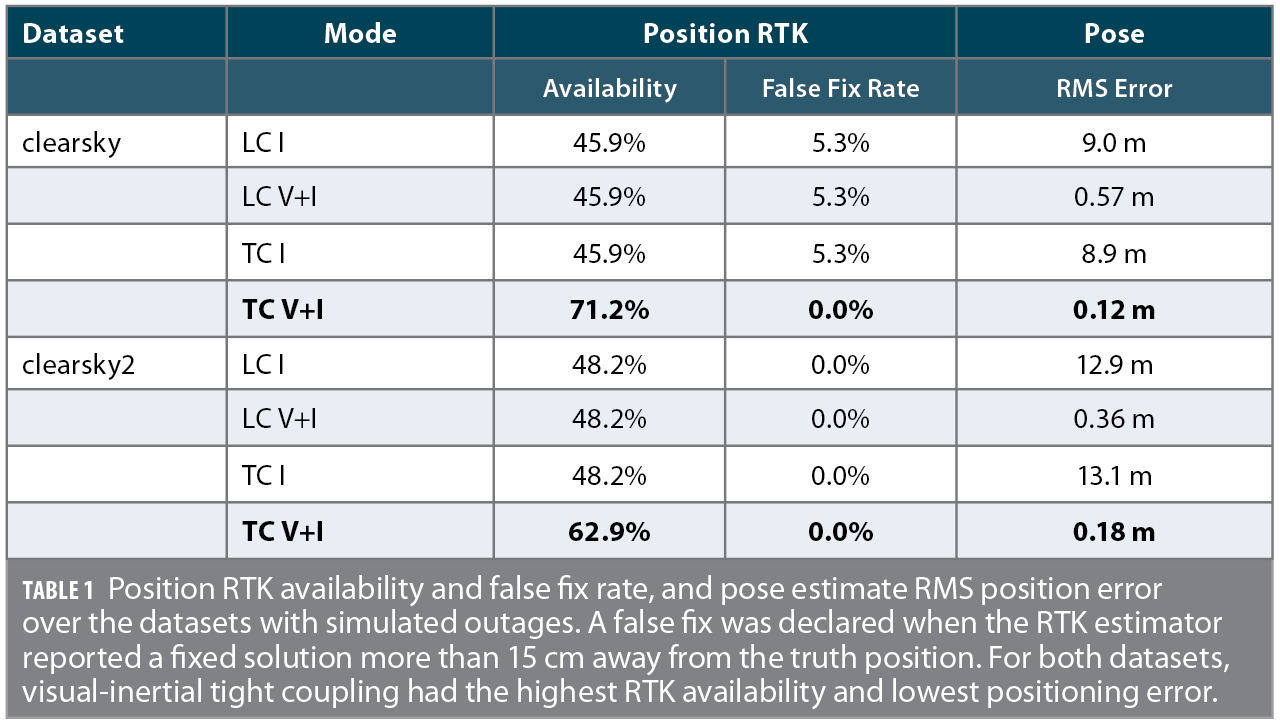
The pose estimation system was run in the four different modes on datasets named clearsky and clearsky2. The clearsky dataset features gentle motion, with velocities limited to 1.0 m/s along any axis, and angular rates limited to 45°/s. The clearsky2 dataset featured more rapid motion and sharp turns, with velocities up to 2.0 m/s, and angular rates up to 100°/s. Figure 5 shows the resulting positioning error in the four modes during these simulated degradations in both datasets; Figure 6 shows the corresponding empirical CDF of positioning errors.
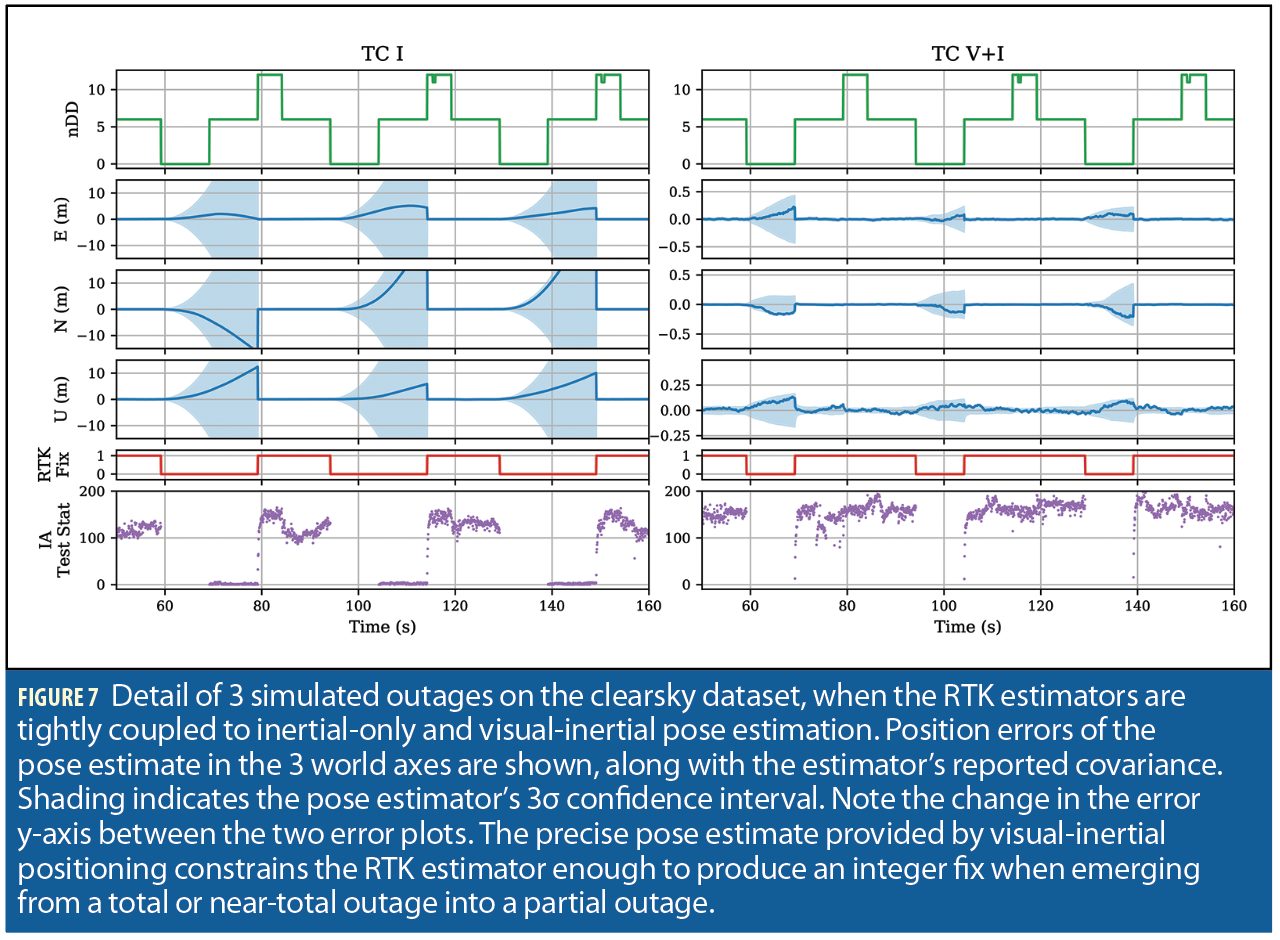
This type of GNSS impairment—a partial outage, followed by a complete outage, followed by a partial outage—provides a clear demonstration of the advantages of visual-inertial tight coupling, as explored in Figure 7. Inertial-only pose propagation with even a smartphone-grade IMU is perfectly capable of providing a centimeter-level accurate pose estimate over deltas of a fraction of a second, which is helpful in retaining a fix during degraded conditions with sharp antenna movements. However, once the RTK fix is lost, be it due to a complete outage, set of measurements corrupted by multipath, or a sudden shift in visible satellites, the IMU-only position estimate rapidly degrades, and after just a couple of seconds no longer provides a useful constraint for RTK integer ambiguity resolution. An IMU-only system must then wait until a sufficient (and usually large) number of satellites is reacquired before it is able to confidently provide an RTK fix again. In contrast, a visual-inertial pose estimator is often able to retain centimeter accuracy indefinitely during an outage, as its drift is primarily determined by the distance traveled rather than time elapsed. After emerging from an outage into still-degraded GNSS conditions, the visual-inertial estimator often still has a strong enough position constraint to improve the RTK fixing success rate.
In both simulated outage datasets, the tightly-coupled visual-inertial estimator was usually able to retain an integer fix during the partial outage following a complete outage, while the loosely-coupled and IMU-only estimators are never able to achieve an integer fix until the simulated degradation ended completely. This caused a large increase in both integer fix rate and positioning accuracy for the tightly-coupled visual-inertial estimator over the other modes, as can be seen in Figure 6.
Real-World Test
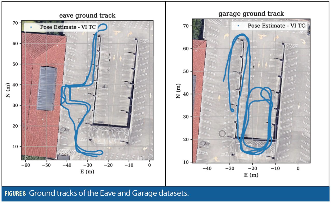
Next, data from the sensors onboard the MAV were collected in challenging real-world GNSS conditions over several sessions on the roof of a parking garage next to a building with an overhanging eave.
In the Eave dataset, the rover makes several passes from an area with a clear view of the sky to underneath the eave, causing outages of all but a few GNSS signals, then moves back to an area with a clear sky view. In the Garage dataset, the rover makes several loops which take it between an area with a somewhat obstructed view of the sky and an area covered by overhanging parking garage structure, which induces essentially total GNSS outages. This dataset additionally provided a challenge for the visual-inertial navigation due to the large contrast changes encountered when entering and leaving the shadows of the overhanging garage. Ground tracks for both datasets are shown in Figure 8.
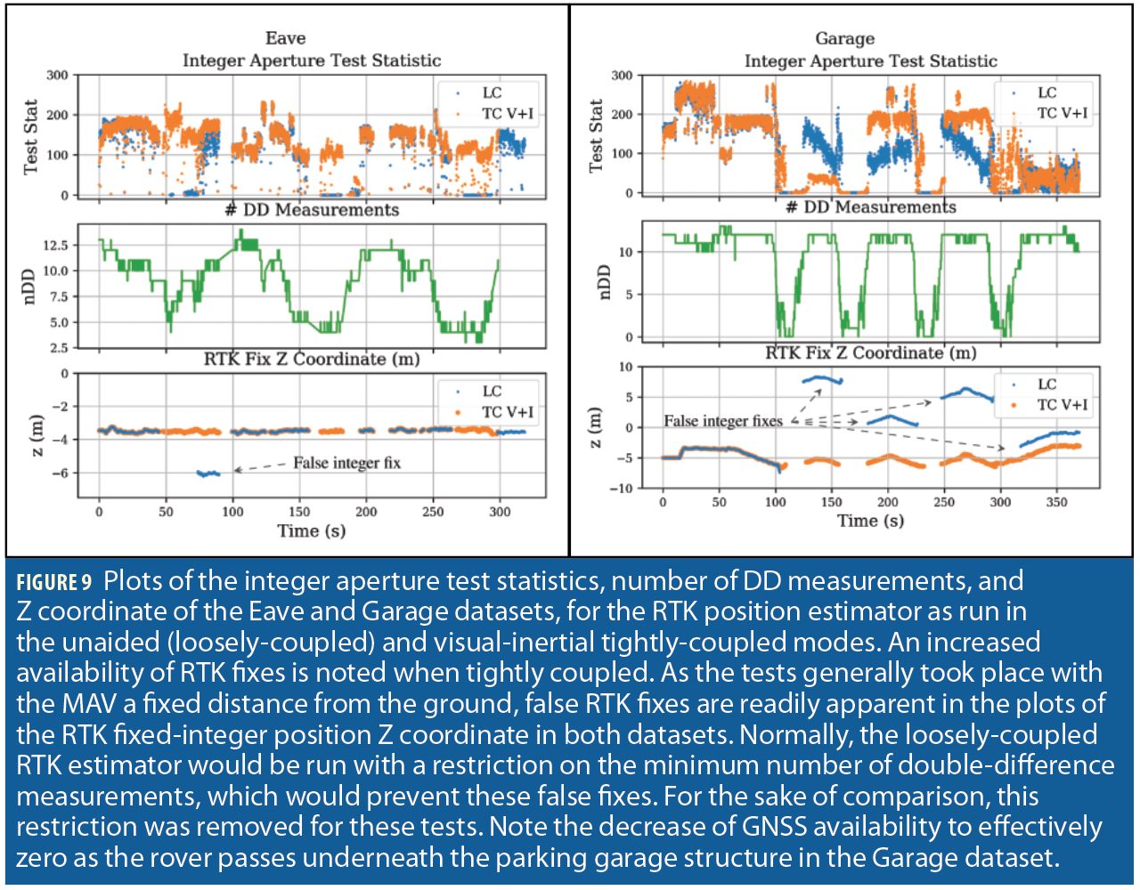
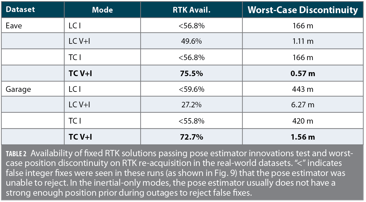
Both datasets take place in challenging GNSS environments. Due to the lack of a clear sky view in these datasets, no truth reference is available. Therefore, they are analyzed via metrics relating to the estimators’ internal consistency. Table I shows the availability of fixed-integer RTK position solutions which additionally passed the central pose estimator innovations test. In all inertial-only cases, false RTK integer fixes were seen in the positioning output. In the loosely-coupled cases, the availability decreased when visual measurements were added, due to the central pose estimator’s increased ability to reject these incorrect integer fixes via innovations testing. In both datasets, integer fixing rates greatly increased when the RTK estimators ran in visual-inertial tightly-coupled mode.
Table 1 shows, for each run, the largest position jump that occurred on the re-acquisition of an innovations-accepted position RTK fix following an outage. Assuming the RTK integer states have been correctly fixed on re-acquisition, this is effectively a measure of the unaided pose estimator drift over the course of the RTK outage. In both the garage and eave datasets, multi-second RTK fix outages occurred in all 4 filter modes due to the challenging GNSS environment. These outages were often too long for the pose estimator to provide a useful position estimate when solely using the smartphone-grade IMU. In contrast, when visual measurements are allowed into the pose estimator, sub-meter accuracy was retained in almost every case over the course of these outages. When the estimator was run in the tightly-coupled mode, this extra constraint allowed earlier RTK fixing at the tail end of an outage, when fewer double-difference measurements were available, increasing the overall solution accuracy.
In the garage dataset, the RTK position estimator spent a large amount of time with an incorrect integer fix in all runs except with tightly coupled visual-inertial positioning. For all modes except tightly-coupled visual-inertial, a heuristic based on the number of DD measurements would normally prevent attempting an integer fix under these conditions. This restriction was disabled for these tests for the sake of fair comparison in environments with few available measurements. When using only the IMU, the pose estimator was unable to confidently reject these false fixes due to its accumulated position uncertainty, and the pose estimate converged to the incorrect RTK position. When running in loosely-coupled mode with visual measurements, the pose estimator correctly rejected the incorrectly-fixed RTK position measurement as it failed the pose estimator’s innovations test, but suffered from increased odometric drift as it consequently spent more time without valid RTK measurements. In contrast, when running in tightly-coupled mode with visual measurements, the enhanced position prior provided by visual-inertial pose estimate allowed the RTK estimator to produce a correctly fixed position measurement, providing increased RTK availability and therefore positioning accuracy.
Conclusions
A multi-antenna carrier phase differential GNSS (CDGNSS) position and orientation (pose) determination system uses camera images and measurements from a smartphone-grade inertial sensor to aid the integer ambiguity resolution process by providing it with a pose prior. Performance tests showed that incorporating visual measurements into a tightly-coupled inertial-CDGNSS system is critical to maintaining a pose estimate accurate enough to support an integer fix when emerging from complete or near-complete GNSS measurement outages.
Acknowledgments
This work was supported in part by the University of Texas Wireless Networking and Communications Group (WNCG), and in part by the Army Research Office under Cooperative Agreement W911NF-19-2-0333. The views and conclusions contained in this document are those of the authors and should not be interpreted as representing the official policies, either expressed or implied, of the Army Research Office or the U.S. Government. The U.S. Government is authorized to reproduce and distribute reprints for Government purposes notwithstanding any copyright notation herein.
This article is based on a paper presented at ION GNSS+ 2020; the complete original version can be found at ion.org/publications/browse.cfm.
Authors

James Yoder is a graduate student in the department of Aerospace Engineering and Engineering Mechanics at the University of Texas at Austin, and a member of the UT Radionavigation Laboratory.

Peter A. Iannucci is a postdoctoral research fellow in the Radionavigation Laboratory at The University of Texas at Austin, and a member of the UT Wireless Networking and Communications Group (WNCG).

Lakshay Narula is a Ph.D. student at The University of Texas at Austin, and a graduate research assistant at the UT Radionavigation Lab.

Todd Humphreys is an associate professor in the department of Aerospace Engineering and Engineering Mechanics at The University of Texas at Austin, where he directs the Radionavigation Laboratory. He holds a Ph.D. in aerospace engineering from Cornell University.


